Table of Contents
Advertisement
Advertisement
Table of Contents
Troubleshooting

Related Manuals for Air Liquide ALW-M170500180


Summary of Contents for Air Liquide ALW-M170500180
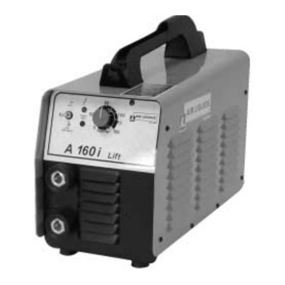
- Page 1 The technical specifications and the wiring diagrams contained in this owner’s manual are valid only for the model that has the part number indicated below. A 160i Lift ALW-M170500180 Air Liquide Welding is a trademark of L’Air Liquide S.A. 08/01...
-
Page 2: Table Of Contents
TABLE OF CONTENTS SAFETY PRECAUTIONS - READ BEFORE USING INSTALLATION OF EQUIPMENT ..........3 PERSONAL PROTECTION . -
Page 3: Safety Precautions - Read Before Using
The publisher does not assume and hereby disclaims any liability to any party for any loss or damage caused by any error or omission in the Air Liquide A 160i Lift Owner’s Manual, whether such error results from negligence, acci- dent or any other causes. -
Page 4: Fire And Explosion Prevention
4. Always wear eye protection with side shields. 3. If the ventilation system is inadequate, use an air respirator. 5. Position a fire resistant screen around the weld- ing area to protect bystanders from radiation, 4. Beware of gas leaks. Shielding gases such as sparks and slag. -
Page 5: Radiation Can Cause Injury
1.7 H.F. RADIATION CAN CAUSE INJURY 1.9 WELDING AND THE EFFECTS OF LOW FREQUENCY AND MAGNETIC FIELDS High frequency (HF) emissions can As welding current flows through welding cables, it interfere with radio navigation, safety devices, can cause electromagnetic fields. To reduce mag- computers and communication equipment. - Page 6 EQUIPMENT INSTALLATION AND MAINTENANCE MUST BE PERFORMED IN COMPLIANCE WITH LOCAL SAFETY STANDARDS. Electric shock could be fatal Fumes and gases may represent Use a protective mask with suit- a safety hazard. able glass filter (at least NR10) to 1. Never touch exposed electrical Fumes and gases generated dur- safeguard eyes.
-
Page 7: Specifications And Description
For options and accessories contact your distrib- utor. 2.2 DESCRIPTION The new A 160i Lift from Air Liquide Welding sets a new standard for constant current, DC arc weld- ing inverters. This 90–270 VAC input (Sinelink) compact unit is a proven performer with serious welding amperage for electrodes up to 4.0 mm... - Page 8 A160i Lift Duty Cycle @ 230 VAC 230 Vac STICK % DUTY CYCLE A160i Lift Duty Cycle @ 115 VAC 115 Vac STICK % DUTY CYCLE...
-
Page 9: Operation
A160i Lift Volt-Ampere Curve 60,00 50,00 230 Vac 40,00 30,00 115 Vac 20,00 10,00 0,00 90 100 110 120 130 140 150 160 170 AMPS AMPS 3. OPERATION 3.1 FRONT PANEL CONTROLS POSITIVE WELD OUTPUT RECEPTACLE For Stick welding using electrodes that operate on DCEP (Direct Current Electrode Positive), connect AMPERAGE ADJUSTMENT CONTROL the electrode cable to this receptacle. -
Page 10: Lift-Start Tig Procedure
1. Touch the tungsten electrode to the workpiece at the welding start point. 2. Hold the electrode to the workpiece for no longer than one second. 3. Slowly lift the electrode from the workpiece. An arc will form when the electrode is lifted. 3.3 BACK PANEL CONTROLS 7. -
Page 11: Installation
4. INSTALLATION 4.1 CONNECTING THE EQUIPMENT TO THE 7. Understand the risk of falling equipment situat- ed in overhead positions. MAIN SUPPLY The equipment is shipped without a plug installed. 4.3 CONNECTION AND PREPARATION OF It works within a wide range of input voltage from EQUIPMENT FOR STICK-ELECTRODE 90 VAC to 270 VAC. -
Page 12: Maintenance And Troubleshooting
4. Turn on the power source using the On – Off 6. Adjust the welding current by turning the switch. Amperage Adjustment control to the desired set- ting. 5. Select the desired welding operation on the Stick / Lift-Start TIG selector switch 7. -
Page 13: Troubleshooting
5.2 TROUBLESHOOTING... -
Page 14: A 160I Lift Electrical Diagram
6. A 160i Lift ELECTRICAL DIAGRAM... -
Page 15: A 160I Lift Spare Parts List
7. A 160i Lift SPARE PARTS LIST A 160i Lift... - Page 16 A 160i Lift...
Need help?
Do you have a question about the ALW-M170500180 and is the answer not in the manual?
Questions and answers