Advertisement
Quick Links
Advertisement

Related Manuals for Equinox Systems EQLED135


Summary of Contents for Equinox Systems EQLED135
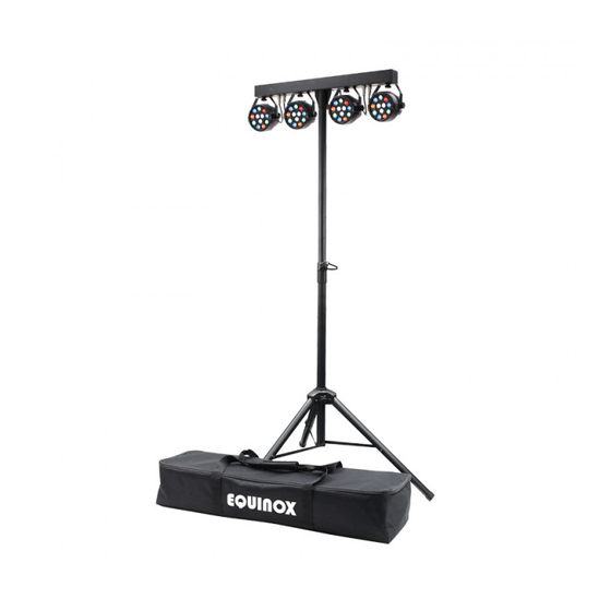
- Page 1 MicroPar Bar System User Manual Order code: EQLED135...
- Page 2 Safety advice WARNING FOR YOUR OWN SAFETY, PLEASE READ THIS USER MANUAL CARE- FULLY BEFORE YOUR INITIAL START-UP! • Before your initial start-up, please make sure that there is no damage caused during transportation. • Should there be any damage, consult your dealer and do not use the equipment. • To maintain the equipment in good working condition and to ensure safe operation, it is necessary for the user to follow the safety instructions and warning notes written in this manual. • Please note that damages caused by user modifications to this equipment are not subject to warranty. CAUTION! CAUTION! TAKE CARE USING KEEP THIS EQUIPMENT THIS EQUIPMENT! AWAY FROM RAIN, HIGH VOLTAGE-RISK MOISTURE AND LIQUIDS OF ELECTRIC SHOCK!!
- Page 3 • Auto, sound active and master/slave • Height adjustable stand modes plus built-in programs • Carry bag included • 0-100% dimming and variable strobe Specifications Power consumption Power supply 100~240V, 50/60Hz Fuse F3A 250V Dimensions (without stand) 200 x 720 x 110mm Weight 5.7kg Order code EQLED135 720mm 110mm 01 - LED display 02 - Function buttons 03 - DMX input 04 - DMX output 05 - IEC power input www.prolight.co.uk POWER INPUT: 100-240V~50/60Hz DMX INPUT DMX OUTPUT MENU DOWN ENTER 06 - Fuse F3A 250V FUSE: F3A 250V 07 - 35mm stand adaptor...
-
Page 4: Static Colour Mode
Operating instructions Operating instructions 0 5 C H d 0 0 1 d. 0 0 1 0 8 C H DMX address & channel settings d 5 1 2 2 0 C H A 1. 0 1 A 1. 0 1 Static colour mode A 1. -
Page 5: Table Of Contents
Operating instructions DMX mode: Operating in a DMX control mode environment gives the user the greatest flexibility when it comes to customising or creating a show. In this mode you will be able to control each individual trait of the fixture and each fixture independently. To access the DMX address mode, press the “MENU” button on the rear of the unit to show d001 on the LED display. Now press the “ENTER” button and use the “UP” and “DOWN” buttons to set the required DMX address. Press the “ENTER” button to confirm the setting. Now use the “UP” and “DOWN” buttons to choose one of the 5/8 or 20 DMX channel modes. Press the “ENTER” button to confirm the setting. 5 channel mode: 20 channel mode: Channel Value Function Channel Value Function 000-255 Master dimmer (0-100%) 000-255 Master dimmer (0-100%) 000-255 Red (0-100%) 000-255 Strobe (slow-fast) 000-255 Green (0-100%) 000-255 Red (0-100%) 000-255 Blue (0-100%) 000-255 Green (0-100%) Par 1 000-255... -
Page 6: Static Colour Mode
Static colour mode: A1. 0 1 To access static colour mode, press the “MENU” button on the rear of the unit to show on the LED display. Now press the “ENTER” button and use the “UP” and “DOWN” buttons to choose A1. 0 1 A1. 1 5 between ~ . Press the “ENTER” button to confirm the setting. To exit out of any of the above options, press the “MENU” button. Colour change mode: A2. 0 1 To access colour change mode, press the “MENU” button on the rear of the unit to show on the LED display. Now press the “ENTER” button and use the “UP” and “DOWN” buttons to choose A2. 0 1 A2. 3 2 between ~ . Press the “ENTER” button to confirm the setting. To exit out of any of the above options, press the “MENU” button. Colour fade modes: A3. 0 1 To access the colour fade modes, press the “MENU” button on the rear of the unit to show on the LED display. Now press the “ENTER” button and use the “UP” and “DOWN” buttons to choose A3. -
Page 7: Operating Instructions
Operating instructions Master/slave mode: To set the master unit select your desired program (static colour, colour change, colour fade, sound active, strobe, auto, colour chase or DMX). SLAu To set the other units in slave mode, press the “MENU” button on the front of the unit to show on the LED display. Press the “ENTER” button to confirm the setting. The unit will now run in sequence with the master unit. To exit out of any of the above options, press the “MENU” button. Please ensure that all slave units are set to the same DMX channel mode as the master unit. www.prolight.co.uk MicroPar Bar System User Manual... -
Page 8: Sound Active Mode
Operating instructions IR remote functions: Button functions: 01 - Sets the unit into blackout on or off 02 - Sets the unit into DMX - Use the ‘+’ and ‘-’ DMX buttons to change the DMX address (001-512) 03 - Puts the unit into static colour mode - Use the ‘+’ and ‘-’ color buttons to select the desired colour. 04 - Puts the unit into colour change mode - Use the ‘+’ and ‘-’ speed buttons to select the desired speed 05 - Puts the unit into colour fade mode - Use the ‘+’ and ‘-’ colour buttons to select the desired program, and the ‘+’ and ‘-’ speed buttons to select the desired program speed 06 - Puts the unit into sound active mode - Use the ‘+’ and ‘-’ colour buttons to select the desired program, – and the ‘+’ and ‘-’ sen buttons to select the desired sensitivity level (1-4) 07 - Puts the unit into strobe mode - Use the ‘+’ and ‘-’ colour buttons to select the desired program, – COLOR and the ‘+’ and ‘-’ speed buttons to select the desired strobe speed 08 - Puts the unit into auto mode - Use the ‘+’ and ‘-’ speed buttons to select the desired speed – SPEED 09 - Puts the unit into colour chase mode - Use the ‘+’ and ‘-’ speed buttons to select the desired speed 10 - Sets the unit into DMX - Use the ‘+’ and ‘-’ DMX – buttons to change the DMX address (001-512) 11 - Sets the static colour/colour programs - Use the ‘+’ and ‘-’ buttons to change the desired colour/program (note: only available in the static colour, colour fade, sound active and strobe modes) 12 - Sets the program speed level - Use the ‘+’ and ‘-’... -
Page 9: White (0
DMX setup Setting the DMX address: The DMX mode enables the use of a universal DMX controller. Each fixture requires a “start address” from 1- 512. A fixture requiring one or more channels for control begins to read the data on the channel indicated by the start address. For example, a fixture that occupies or uses 7 channels of DMX and was addressed to start on DMX channel 100, would read data from channels: 100,101,102,103,104,105 and 106. Choose a start address so that the channels used do not overlap. E.g. the next unit in the chain starts at 107. DMX 512: DMX (Digital Multiplex) is a universal protocol used as a form of communication between intelligent fixtures and controllers. A DMX controller sends DMX data instructions form the controller to the fixture. DMX data is sent as serial data that travels from fixture to fixture via the DATA “IN” and DATA “OUT” XLR terminals located on all DMX fixtures (most controllers only have a data “out” terminal). DMX linking: DMX is a language allowing all makes and models of different manufactures to be linked together and operate from a single controller, as long as all fixtures and the controller are DMX compliant. To ensure proper DMX data transmission, when using several DMX fixtures try to use the shortest cable path possible. The order in which fixtures are connected in a DMX line does not influence the DMX addressing. For example; a fixture assigned to a DMX address of 1 may be placed anywhere in a DMX line, at the beginning, at the end, or anywhere in the middle. When a fixture is assigned a DMX address of 1, the DMX controller knows to send DATA assigned to address 1 to that unit, no matter where it is located in the DMX chain. DATA cable (DMX cable) requirements (for DMX operation): This fixture can be controlled via DMX-512 protocol. The DMX address is set on the back of the unit. Your unit and your DMX controller require a standard 3-pin XLR connector for data input/output, see image below. Further DMX cables can be purchased from all good sound and lighting suppliers or Pro Light Concepts dealers. -
Page 10: White (0
DMX setup Notice: Be sure to follow the diagrams below when making your own cables. Do not connect the cables shield conductor to the ground lug or allow the shield conductor to come in contact with the XLRs outer casing. Grounding the shield could cause a short circuit and erratic behaviour. Special note: Line termination: When longer runs of cable are used, Termination reduces signal transmission you may need to use a terminator on problems and interferance. it is always advisable to connect a DMX terminal, the last unit to avoid erratic behaviour. (resistance 120 Ohm 1/4 W) between pin 2 Using a cable terminator will decrease (DMX-) and pin 3 (DMX+) of the last fixture. the possibilities of erratic behaviour. (3-pin - Order ref: CABL9O, 5-pin - Order ref: CABL89) 5-pin XLR DMX connectors: Some manufactures use 5-pin XLR connectors for data transmission in place of 3-pin. 5-pin XLR fixtures may be implemented in a 3-pin XLR DMX line. When inserting standard 5-pin XLR connectors in to a 3-pin line a cable adaptor must be used. The diagram below details the correct cable conversion. -
Page 11: White (0
WEEE notice Correct Disposal of this Product (Waste Electrical & Electronic Equipment) (Applicable in the European Union and other European countries with separate collection systems) This marking shown on the product or its literature, indicates that it should not be disposed of with other household wastes at the end of its working life. To prevent possible harm to the environment or human health from uncontrolled waste disposal, please separate this from other types of wastes and recycle it responsibly to promote the sustainable reuse of material resources. Household users should contact either the retailer where they purchased this product, or their local government office, for details of where and how they can take this item for environmentally safe recycling. Business users should contact their supplier and check the terms and conditions of the purchase contract. This product should not be mixed with other commercial wastes for disposal. www.prolight.co.uk MicroPar Bar System User Manual... -
Page 12: White (0
www.prolight.co.uk MicroPar Bar System User Manual...
Need help?
Do you have a question about the EQLED135 and is the answer not in the manual?
Questions and answers