Table of Contents
Advertisement
Quick Links
Advertisement
Table of Contents

Related Manuals for Equinox Systems EQLED12N


Summary of Contents for Equinox Systems EQLED12N
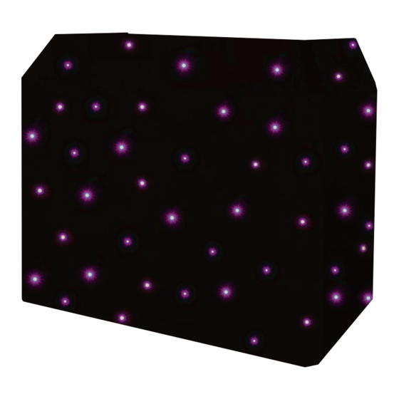
- Page 1 DJ Booth Quad-colour Starcloth User Manual Order code: EQLED12N...
-
Page 2: Safety Advice
Safety advice WARNING - FOR YOUR OWN SAFETY, PLEASE READ THIS USER MANUAL CAREFULLY BEFORE YOUR INITIAL START-UP! • Before your initial start-up, please make sure that there is no damage caused during transportation. • Should there be any damage, consult your dealer and do not use the equipment. • To maintain the equipment in good working condition and to ensure safe operation, it is necessary for the user to follow the safety instructions and warning notes written in this manual. • Please note that damages caused by user modifications to this equipment are not subject to warranty. CAUTION! CAUTION! TAKE CARE USING KEEP THIS EQUIPMENT THIS EQUIPMENT! AWAY FROM RAIN, HIGH VOLTAGE-RISK MOISTURE AND LIQUIDS OF ELECTRIC SHOCK!! - Page 3 Product overview & technical specifications DJ Booth Quad-colour Starcloth Featuring 72 quad-colour 5050 LEDs, this DJ Booth starcloth comes supplied with an advanced DMX controller. The controller features solid colour selection coupled with pattern and speed control, allowing the DJ to match the starcloth colour to any other room lighting. Supplied with heavy duty carry bag. Cloth: • 72 quad-colour 5050 LEDs (RGBW) • Fast fixx™ velcro tabs • Low reflection, fire retardant material • Includes an advanced DMX controller • Carry bag included Controller: • DMX channels: 3, 9 or 28 selectable Specifications Controller • Static colour, auto, DMX, sound active Power supply 100~240V, 50/60Hz and master/slave modes Fuse T1A 250V • IEC power input Dimensions 55 x 205 x 145mm • 3-Pin XLR input/output 205mm 145mm QUAD STARCLOTH CONTROLLER DOWN ENTER PUSH DMX OUTPUT...
-
Page 4: Technical Specifications
Technical specifications QUAD STARCLOTH CONTROLLER DOWN ENTER QUAD STARCLOTH CONTROLLER QUAD STARCLOTH CONTROLLER DOWN ENTER DOWN ENTER PUSH DMX OUTPUT DMX INPUT OUTPUT TO STARCLOTH PUSH PUSH www.prolight.co.uk DMX OUTPUT DMX INPUT OUTPUT TO STARCLOTH DMX OUTPUT DMX INPUT OUTPUT TO STARCLOTH POWER SUPPLY: 100-240V~50/60Hz FUSE: T1A 250V... -
Page 5: Operating Instructions
Operating instructions mode: To access the DMX mode, from the home menu press “ENTER” button and use the “UP/DOWN” buttons to highlight “DMX”. Now press the “ENTER” button and use the “UP” and “DOWN” buttons to choose between the following settings; Channel Set: Press the “ENTER” button and use the “UP” and “DOWN” buttons to select between the 3/9 or 28 channel modes. Press the “ESC” button to confirm the setting. DMX Fail: Press the “ENTER” button and use the “UP” and “DOWN” buttons to select between Auto, Hold, Blackout or Sound modes. Press the “ESC” button to confirm the setting. Address Set: Press the “ENTER” button and use the “UP” and “DOWN” buttons to select the DMX address required between 001 and 512. Press the “ESC” button to confirm the setting. Signal In: This function is to check whether the controller is receiving a DMX input. To exit out of any of the above options, press the “ESC” button. 3 channel mode: Channel Value Function 000-009 Blackout 010-019 020-029 Green Channel Value Function 030-039 Blue 000-009 Static pattern 1 040-049 White 010-019 Static pattern 2... - Page 6 Operating instructions 9 channel mode: Channel Value Function 000-006 Blackout 007-013 014-020 Green 021-027 Blue 028-034 White 035-041 Yellow 042-048 Purple 049-055 Cyan 056-062 Pink 063-069 Dark Orange 070-076 Light Yellow 077-083 Light Purple 084-090 Gold 091-097 Light Green 098-104 Light Pink 105-111 Dark Purple 112-118 Orange 119-125 All On...
- Page 7 Operating instructions 9 channel mode cont...: Channel Value Function 000-009 Stop (static and multi-colour patterns, CH1 between 000-167) 010-255 Slow-fast (static and multi-colour patterns, CH1 between 000-167) 000-255 Slow-fast (auto patterns, CH1 between 168-251) 000-255 Red 0-100% (CH1 between 000-006) 000-255 Green 0-100% (CH1 between 000-006) 000-255 Blue 0-100% (CH1 between 000-006) 000-255 White 0-100% (CH1 between 000-006) 000-034 Static pattern 1 (CH1 between 007-167) 035-069 Static pattern 2 (CH1 between 007-167) 070-104 Static pattern 3 (CH1 between 007-167) 105-139 Static pattern 4 (CH1 between 007-167) 140-174 Static pattern 5 (CH1 between 007-167) 175-209 Static pattern 6 (CH1 between 007-167) 210-255 Static pattern cycle (1-6) (CH1 between 010-129) 000-029 Multi colour pattern 1 030-059 Multi colour pattern 2 060-089 Multi colour pattern 3 090-119 Multi colour pattern 4...
- Page 8 Operating instructions 28 channel mode: Channel Value Function 000-009 Blackout 010-019 020-029 Green 030-039 Blue 040-049 White 050-059 Yellow 060-069 Purple 070-079 Cyan 080-089 Pink 090-099 Dark Orange 100-109 Light Yellow 110-119 Warm White 120-129 All On 130-139 Pattern 1 140-149 Pattern 2 150-159 Pattern 3 160-169 Pattern 4 170-179 Pattern 5...
- Page 9 Operating instructions 28 channel mode cont...: Channel Value Function 000-255 Red 1 0-100% (CH1 between 000-009) 000-255 Green 1 0-100% (CH1 between 000-009) 000-255 Blue 1 0-100% (CH1 between 000-009) 000-255 White 1 0-100% (CH1 between 000-009) 000-255 Red 2 0-100% (CH1 between 000-009) 000-255 Green 2 0-100% (CH1 between 000-009) 000-255 Blue 2 0-100% (CH1 between 000-009) 000-255 White 2 0-100% (CH1 between 000-009) 000-255 Red 3 0-100% (CH1 between 000-009) 000-255 Green 3 0-100% (CH1 between 000-009) 000-255 Blue 3 0-100% (CH1 between 000-009) 000-255 White 3 0-100% (CH1 between 000-009) 000-255 Red 4 0-100% (CH1 between 000-009) 000-255 Green 4 0-100% (CH1 between 000-009) 000-255 Blue 4 0-100% (CH1 between 000-009) 000-255 White 4 0-100% (CH1 between 000-009) 000-255 Red 5 0-100% (CH1 between 000-009) 000-255 Green 5 0-100% (CH1 between 000-009) 000-255 Blue 5 0-100% (CH1 between 000-009)
- Page 10 Operating instructions Auto mode: To access the Auto mode, from the home menu press “ENTER” button and use the “UP/DOWN” buttons to highlight “Auto”. Now press the “ENTER” button and use the “UP” and “DOWN” buttons to select between “Program01” to “Program12”. Press the “ENTER” button and use the “UP” and “DOWN” buttons to select the speed between “Speed: 00” to “Speed: 99”. Press the “ESC” button to confirm the setting. To exit out of any of the above options, press the “ESC” button. Sound mode: To access the Sound mode, from the home menu press “ENTER” button and use the “UP/DOWN” buttons to highlight “Sound”. Now press the “ENTER” button and use the “UP” and “DOWN” buttons to choose between the following settings; Sound Program: Press the “ENTER” button and use the “UP” and “DOWN” buttons to select between “Sound Program :01” to “Sound Program :12”. Press the “ESC” button to confirm the setting. Sound Sensitivity: Press the “ENTER” button and use the “UP” and “DOWN” buttons to select the sound sensitivity between “Sensitivity :00” to “Sensitivity :31”. Press the “ESC” button to confirm the setting. To exit out of any of the above options, press the “ESC” button. Static colour mode: To access the Static colour mode, from the home menu press “ENTER” button and use the “UP/DOWN” buttons to highlight “Static”. Now press the “ENTER” button and use the “UP” and “DOWN” buttons to select the colour required between “C01”...
- Page 11 Operating instructions Factory reset: To perform a factory reset, from the home menu press “ENTER” button and use the “UP/DOWN” buttons to highlight “Set”. Now press the “ENTER” button and use the “UP” and “DOWN” buttons to select “Factory reset”. Press the “ENTER” button and use the “UP” and “DOWN” buttons to select “Yes”. Press the “ENTER” button, a confirmation message will appear. Use the “UP” and “DOWN” but- tons to select “Yes”. Press the “ENTER” button, the controller will now perform a factory reset. www.prolight.co.uk DJ Booth Quad-colour Starcloth User Manual...
-
Page 12: Dmx Setup
DMX setup Setting the DMX address: The DMX mode enables the use of a universal DMX controller. Each fixture requires a “start address” from 1- 512. A fixture requiring one or more channels for control begins to read the data on the channel indicated by the start address. For example, a fixture that occupies or uses 7 channels of DMX and was addressed to start on DMX channel 100, would read data from channels: 100,101,102,103,104,105 and 106. Choose a start address so that the channels used do not overlap. E.g. the next unit in the chain starts at 107. DMX 512: DMX (Digital Multiplex) is a universal protocol used as a form of communication between intelligent fixtures and controllers. A DMX controller sends DMX data instructions form the controller to the fixture. DMX data is sent as serial data that travels from fixture to fixture via the DATA “IN” and DATA “OUT” XLR terminals located on all DMX fixtures (most controllers only have a data “out” terminal). DMX linking: DMX is a language allowing all makes and models of different manufactures to be linked together and operate from a single controller, as long as all fixtures and the controller are DMX compliant. To ensure proper DMX data transmission, when using several DMX fixtures try to use the shortest cable path possible. The order in which fixtures are connected in a DMX line does not influence the DMX addressing. For example; a fixture assigned to a DMX address of 1 may be placed anywhere in a DMX line, at the beginning, at the end, or anywhere in the middle. When a fixture is assigned a DMX address of 1, the DMX controller knows to send DATA assigned to address 1 to that unit, no matter where it is located in the DMX chain. DATA cable (DMX cable) requirements (for DMX operation): This fixture can be controlled via DMX-512 protocol. The DMX address is set on the back of the unit. Your unit and your DMX controller require a standard 3-pin XLR connector for data input/output, see image below. Further DMX cables can be purchased from all good sound and lighting suppliers or Pro Light Concepts dealers. -
Page 13: Line Termination
DMX setup Notice: Be sure to follow the diagrams below when making your own cables. Do not connect the cables shield conductor to the ground lug or allow the shield conductor to come in contact with the XLRs outer casing. Grounding the shield could cause a short circuit and erratic behaviour. Special note: Line termination: When longer runs of cable are used, Termination reduces signal transmission you may need to use a terminator on problems and interference. it is always advisable to connect a DMX terminal, the last unit to avoid erratic behaviour. (resistance 120 Ohm 1/4 W) between pin 2 Using a cable terminator will decrease (DMX-) and pin 3 (DMX+) of the last fixture. the possibilities of erratic behaviour. (3-pin - Order ref: CABL90, 5-pin - Order ref: CABL89) 5-pin XLR DMX connectors: Some manufactures use 5-pin XLR connectors for data transmission in place of 3-pin. 5-pin XLR fixtures may be implemented in a 3-pin XLR DMX line. When inserting standard 5-pin XLR connectors in to a 3-pin line a cable adaptor must be used. The diagram below details the correct cable conversion. -
Page 14: Weee Notice
WEEE notice Correct Disposal of this Product (Waste Electrical & Electronic Equipment) (Applicable in the European Union and other European countries with separate collection systems) This marking shown on the product or its literature, indicates that it should not be disposed of with other household wastes at the end of its working life. To prevent possible harm to the environment or human health from uncontrolled waste disposal, please separate this from other types of wastes and recycle it responsibly to promote the sustainable reuse of material resources. Household users should contact either the retailer where they purchased this product, or their local government office, for details of where and how they can take this item for environmentally safe recycling. Business users should contact their supplier and check the terms and conditions of the purchase contract. This product should not be mixed with other commercial wastes for disposal. www.prolight.co.uk DJ Booth Quad-colour Starcloth User Manual... -
Page 15: Optional Accessories
Optional accessories Please contact your local retailer to purchase these accessories. Optional Overhead kit - This allows the user to create a full light show Overhead kit close-up without the need to have separate lighting stands and how it connects to the DJ Booth System Order code: EQLED12E Lightweight DJ Booth MKII Optional Black Lycra available to purchase Optional Black Starcloth... - Page 16 www.prolight.co.uk DJ Booth Quad-colour Starcloth User Manual...
Need help?
Do you have a question about the EQLED12N and is the answer not in the manual?
Questions and answers