Videx VRVK Series Installation Handbook
"6 wire" bus one way, two way vandal resistant videokit
Hide thumbs
Also See for VRVK Series:
- Installation handbook (28 pages) ,
- Installation handbook (28 pages) ,
- Installation handbook (28 pages)

Related Manuals for Videx VRVK Series


Summary of Contents for Videx VRVK Series
- Page 1 English VIDEOKIT VRVK SERIES “6 Wire” bus one way, two way vandal resistant videokit VRVK VRVKC 6256 Installation handbook We recommend 66250693-EN This equipment is installed by a V 3.4 Competent Electrician, Security or 31/08/16 Communications Engineer.
-
Page 2: Table Of Contents
VRVK/6256 Series “6 wire Bus” Vandal Resistant videokit Index Introduction ....................................2 System components and available versions ..........................3 General directions for installation ..............................5 Troubleshooting guide .................................. 6 Art. VR4KCM Camera module ................................ 7 Art. VR4KAMK Speaker unit ................................8 Art. VR4KCL Digital codelock ............................... 10 4000 Series surface and flush mounting door station installation .................. -
Page 3: System Components And Available Versions
VRVK/6256 Series “6 wire Bus” Vandal Resistant videokit System components and available versions VRVK/6256 Colour videokit. OUTDOOR INDOOR STATION STATION 135,0 45,0 15,70 43,0 Videophone Art. 6256 pag. 15 Camera unit Art. VR4KCM pag. 7 ACCESSORIES Power supply Speaker unit Art. 850K Art. VR4KAMK pag. - Page 4 VRVK/6256 Series “6 wire Bus” Vandal Resistant videokit System components and available versions VRVKC/6256 Colour videokit plus a codelock module. OUTDOOR INDOOR 135,0 45,0 15,70 43,0 STATION STATION Videophone Camera unit Art. 6256 Art. VR4KCM pag. 15 pag. 7 Speaker unit Art. VR4KAMK pag.
-
Page 5: General Directions For Installation
VRVK/6256 Series “6 wire Bus” Vandal Resistant videokit General directions for installation CONNECTION TO MAINS The system must be installed according to national rules in force, in particular we recommend to: • Connect the system to the mains through an all-pole circuit breaker which shall have contact separation of at least 3mm in each pole and shall disconnect all poles simultaneously;... -
Page 6: Troubleshooting Guide
VRVK/6256 Series “6 wire Bus” Vandal Resistant videokit Troubleshooting guide In case of system failure, try the following preliminary checks: • Check that the cables are connected as shown in the installation diagram and that the cables are firmly fixed into the relevant terminals; •... - Page 7 VRVK/6256 Series “6 wire Bus” Vandal Resistant videokit Art. VR4KCM Camera module Art.130 = Active low camera enable = Heater- = Ground = Video Sig. Sync+ = Heater+ = Video Sig. Sync- +20 = +20Vdc power supply = Video Sig. Coax +12 = +12Vdc power supply NC ON COAX SL...
- Page 8 VRVK/6256 Series “6 wire Bus” Vandal Resistant videokit Art. VR4KAMK Speaker unit Art.140 Amplifier for VR4KV Series Videokits P1 = Red / Rosso P2 = White / Bianco – .. = Blue / Blu Made in Italy NO NC C PTE SL BS 2 1 +12 +20 Speaker Reassurance Microphone...
-
Page 9: Art. Vr4Kamk Speaker Unit
VRVK/6256 Series “6 wire Bus” Vandal Resistant videokit Art. VR4KAMK Speaker unit When the door open relay operating mode is set to “capacitor discharge”*, one terminal of the electric lock must be connected to ground while the second must be connected to “NO” terminal. The “NO” terminal will supply a temporary voltage when the speaker unit receives the door open command. - Page 10 GENERAL DIRECTIONS FOR INSTALLATION • In order to achieve the best results from the schematics described it is necessary to install only original VIDEX equipment, strictly keeping to the items indicated on each schematic and follow these General Directions for Installation: •...
-
Page 11: Art. Vr4Kcl Digital Codelock
VRVK/6256 Series “6 wire Bus” Vandal Resistant videokit Art. VR4KCL Digital codelock BUILT-IN RELAYS – BACK EMF PROTECTION The codelocks includes selectable back EMF protection on the relays. The jumpers marked MOV (One jumper for each relay) are used to select the protection type. When using a fail secure lock with connections C & NO the jumper should be in the NO position. When using a fail open lock with connections C &... - Page 12 VRVK/6256 Series “6 wire Bus” Vandal Resistant videokit Art. VR4KCL Digital codelock FLOW CHART FIRST TIME SIX TIMES 1 ENTER “111111” FACTORY “ENGINEER’S CODE” Press Enter PRESET (Red LED will be ON) TYPE AGAIN SIX TIMES “1” CONFIRM OR CHANGE OR THE NEW ENGINEER’S “ENGINEER’S CODE”...
- Page 13 VRVK/6256 Series “6 wire Bus” Vandal Resistant videokit 4000 Series Surface and flush mounting door station installation EXAMPLE: INSTALLING A FOUR MODULE OUTDOOR STATION fig. 1 fig. 2 fig. 3 fig. 4 fig. 5 fig. 6 fig. 7 fig. 8 fig.
-
Page 14: 4000 Series Surface And Flush Mounting Door Station Installation
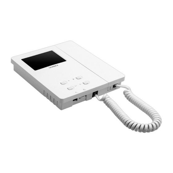
VRVK/6256 Series “6 wire Bus” Vandal Resistant videokit 4000 Series Surface and flush mounting door station installation INSTALLING A SURFACE MOUNT DOOR STATION 1. Place the surface box against the wall (165-170cm between the top of the box and the floor level as shown in Fig. 1) and mark the fixing holes for the wall plugs and the hole for the cables E (fig. 2). - Page 15 VRVK/6256 Series “6 wire Bus” Vandal Resistant videokit Art. 6256 3.5" colour videophone 27 mm 144 mm PT3 PT2 Fig. 1 Fig. 2 DESCRIPTION Surface mount videophone incorporating a 3.5” Hi-Res full colour active matrix LCD monitor specific for “6 wire” videokit (VK4K, VRVK and VK8K range).
-
Page 16: Art. 6256 3.5" Colour Videophone
VRVK/6256 Series “6 wire Bus” Vandal Resistant videokit Art. 6256 3.5" colour videophone LEDS CONTROLS Door open LED. SW1 Call tone volume controll (3 levels). Can be used to indicate the status of a door or gate. It requires a switched 12Vdc connection to terminal “LD” . Privacy ON/OFF LED. - Page 17 VRVK/6256 Series “6 wire Bus” Vandal Resistant videokit Art. 6256 3.5" colour videophone SIGNALS ON CONNECTION BOARD 20Vdc Input/Output (As input 16÷20Vdc 0,5A – as output 20Vdc 0,5A max) – Ground reference for +V terminal. Speech line output from handset’s microphone and data signal (Approx. 12V in stand-by, 5V during a conversation) Speech line input toward the handset’s loudspeaker (Approx.
- Page 18 VRVK/6256 Series “6 wire Bus” Vandal Resistant videokit 6200 Series Videophone wall mounting instructions Fig. 1 Fig. 2 Fig. 3 Fig. 4 Fig. 5 Fig. 6 1. In order to install the videophone, it is necessary to remove the cover, which contains all the electronics, from the base: firstly disconnect the handset from the videophone (by removing its plug from the videophone), then press lightly the bottom part of the videophone and simultaneously pulling outwards the upper part as shown in Fig.
-
Page 19: Installation Diagrams
This manual has been written and revised carefully. The instructions and the descriptions which are included in it are referred to VIDEX parts and are correct at the time of print. However, subsequent VIDEX parts and manuals, can be subject to changes without notice. - Page 20 Art.140 Art.140 Title: Data creazione: Foglio 22/10/2015 Titolo: Data modifica: 01/12/2015 Videx Electronics S.p.A. Notes: Autore: Marco Rongoni Via del Lavoro 1, 63846 Monte Giberto (FM) Note: Cod.File: Phone: +39 0734 631669 - Fax +39 0734 631669 vrvk62h-001.dwg www.videx.it - info@videx.it VRVK/6256 Series - Installation handbook 66250693-EN - V 3.4 - 31/08/16...
- Page 21 VRVK/6256 Series “6 wire Bus” Vandal Resistant videokit Installation diagrams VIDEOKIT VRVK-2/6256, VRVK-2S/6256 1 2 3 4 5 6 7 8 1 2 3 4 5 6 7 8 01/12/2015 01/12/2015 Marco Rongoni vrvk62h-002.dwg VRVK/6256 Series - Installation handbook 66250693-EN - V 3.4 - 31/08/16...
- Page 22 VR4KAMK-1 Art.140 Title: Data creazione: Foglio 01/12/2015 Titolo: Data modifica: 01/12/2015 Videx Electronics S.p.A. Notes: Autore: Marco Rongoni Via del Lavoro 1, 63846 Monte Giberto (FM) Note: Cod.File: Phone: +39 0734 631669 - Fax +39 0734 631669 vrvk62h-003.dwg www.videx.it - info@videx.it VRVK/6256 Series - Installation handbook 66250693-EN - V 3.4 - 31/08/16...
- Page 23 VRVK/6256 Series “6 wire Bus” Vandal Resistant videokit Installation diagrams VIDEOKIT VRVKC-2/6256, VRVKC-2S/6256 1 2 3 4 5 6 7 8 1 2 3 4 5 6 7 8 01/12/2015 01/12/2015 Marco Rongoni vrvk62h-004.dwg VRVK/6256 Series - Installation handbook 66250693-EN - V 3.4 - 31/08/16...
- Page 24 VRVK/6256 Series “6 wire Bus” Vandal Resistant videokit Installation diagrams VIDEOKIT VRVK-2/6256, VRVK-2S/6256 WITH ART. 316 1 2 3 4 5 6 7 8 1 2 3 4 5 6 7 8 01/12/2015 01/12/2015 Marco Rongoni vrvk62h-005.dwg VRVK/6256 Series - Installation handbook 66250693-EN - V 3.4 - 31/08/16...
- Page 25 Art.140 Art.140 Title: Data creazione: Foglio 29/10/2015 Titolo: Data modifica: 29/10/2015 Videx Electronics S.p.A. Notes: Autore: Marco Rongoni Via del Lavoro 1, 63846 Monte Giberto (FM) Note: Cod.File: Phone: +39 0734 631669 - Fax +39 0734 631669 vrvk-1-001-2e.d www.videx.it - info@videx.it VRVK/6256 Series - Installation handbook 66250693-EN - V 3.4 - 31/08/16...
- Page 26 VRVK/6256 Series “6 wire Bus” Vandal Resistant videokit Notes VRVK/6256 Series - Installation handbook 66250693-EN - V 3.4 - 31/08/16...
- Page 27 VRVK/6256 Series “6 wire Bus” Vandal Resistant videokit Notes VRVK/6256 Series - Installation handbook 66250693-EN - V 3.4 - 31/08/16...
- Page 28 MANUFACTURER CUSTOMER SUPPORT VIDEX ELECTRONICS S.P.A. All Countries: VIDEX ELECTRONICS S.P.A. Via del Lavoro, 1 - 63846 Monte Giberto (FM) Italy www.videx.it - technical@videx.it Tel (+39) 0734 631669 - Fax (+39) 0734 632475 Tel: +39 0734-631669 - Fax: +39 0734-632475 www.videx.it - info@videx.it...
Need help?
Do you have a question about the VRVK Series and is the answer not in the manual?
Questions and answers