
Related Manuals for Videx VR120DK-1


Summary of Contents for Videx VR120DK-1
- Page 1 THE POWER TO SECURE ONE BUTTON DOOR ENTRY KIT VR120DK-1 TECHNICAL MANUAL EDITION 1.0...
-
Page 2: Table Of Contents
Accessories Connection Guide 14 - 15 Wiring Diagrams 16 - 17 • 1 button audio panel with 1 audiophone • 1 button audio panel with 3 audiophones Trouble Shooting Guide 18 - 19 Notes Page 2 VR120DK-1 TECHNICAL MANUAL EDITION 1.1... -
Page 3: Manual Introduction
THE POWER TO SECURE MANUAL INTRODUCTION he information in this manual is intended as an installation and commissioning guide for the Videx VR120 vandal resistant one button audio intercom kit. This manual should be read carefully before the installation commences. Any damage caused to the equipment due to faulty installations where the information in this manual has not been followed is not the responsibility of Videx Security Ltd. -
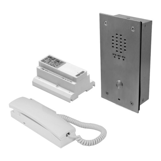
Page 4: System Components
Speech volume adjustments are carried out at the door panel using a small trimmer driver. adjustment for speech volume adjustment for speech volume level at the apartment (microphone) at the door station (speaker) Page 4 VR120DK-1 TECHNICAL MANUAL EDITION 1.1... - Page 5 Switched 0V output to switch on video PSU. (0V throughout a call, open collector in standby) Switched 0V output to switch on camera. (0V throughout a call, open collector in standby) mic and speaker volume POTS reassurance tone jumper 4 way dip-switch terminal connections VR120DK-1 TECHNICAL MANUAL EDITION 1.1 Page 5...
-
Page 6: Panel And Back Box Dimensions
VR120 panel back box options available, a standard flush back box, a flush back box with bezel and a surface back box with rainshield (see below). FRONT PANEL FLUSH (VRFB120x220) FLUSH WITH BEZEL SURFACE WITH (VRBB120x220) RAINSHIELD (VRSB120x220) Page 6 VR120DK-1 TECHNICAL MANUAL EDITION 1.1... -
Page 7: Power Supply (Art.520M)
Art.512A is an extension sounder that can be wall mounted and will ring whenever the audiophone it is connected to rings. The 512A requires an electronic calltone input. Connections Terminal Function Condition Current Rating (mA) Calltone input During a call 100mA 0V (GND) 105mA VR120DK-1 TECHNICAL MANUAL EDITION 1.1 Page 7... -
Page 8: Es/1 Extension Strobe
Normally open relay 1 connection Max. current and Normally closed relay 1 connection voltage for each relay Common relay 2 connection 5A @ 230Vac Normally open relay 2 connection Art.506N Normally closed relay 2 connection Page 8 VR120DK-1 TECHNICAL MANUAL EDITION 1.1... -
Page 9: Installation
Use the following cable types and the tables as a guide to ensure that the best possible performance is achieved. VR120DK-1 TECHNICAL MANUAL EDITION 1.1 Page 9... - Page 10 The power supply ideally should be located as close to the door panel as possible, typically between 20 - 30m. Maximum acceptable resistance for above connections = 3 Ohms or less for best possible performance. Page 10 VR120DK-1 TECHNICAL MANUAL EDITION 1.1...
-
Page 11: Block Diagram
Additional cores will be required for auxiliary devices such as push to exit buttons, fireman switches, fail safe lock release etc. If more than one intercom panel is being used then an additional core for the busy (BSY) connection between intercom panels will be required. VR120DK-1 TECHNICAL MANUAL EDITION 1.1 Page 11... -
Page 12: Panel And Back Box Installation
Fig 2 and Fig.3). All cables should loop down and then back up to the termination connections to avoid any water travelling along the cable and onto the pcb. FLUSH BACK BOX (VRFB120x280) Fig.1 FRONT VIEW REAR VIEW BEZEL BACK BOX (VRBB120x280) Fig.2 FRONT VIEW REAR VIEW Page 12 VR120DK-1 TECHNICAL MANUAL EDITION 1.1... -
Page 13: Panel Care
Cleaners that cannot be used: • Chloride containing cleaners. • Hydrochloric acid based cleaners. • Sidol stainless steel cleaner (can affect engraving). • Hydrochloride bleaches. • Silver cleaners. VR120DK-1 TECHNICAL MANUAL EDITION 1.1 Page 13... -
Page 14: Testing The Installation
In some instances a separate 12Vdc power supply may be required when connecting an extension strobe when several 12Vdc devices are connected on the system, this is to avoid excessive current draw on the existing power supply. Extension Sounder Page 14 VR120DK-1 TECHNICAL MANUAL EDITION 1.1... - Page 15 THE POWER TO SECURE Extension Strobe Push to Exit (push to make) Dry Relay Contacts (Art.506N Relay) VR120DK-1 TECHNICAL MANUAL EDITION 1.1 Page 15...
-
Page 16: Wiring Diagrams
THE POWER TO SECURE WIRING DIAGRAMS 1 way audio system with a VR120/136-1 door panel connected to an Art.3011 audiophone. Page 16 VR120DK-1 TECHNICAL MANUAL EDITION 1.1... -
Page 17: Button Audio Panel With 3 Audiophones
THE POWER TO SECURE 1 way audio system with a VR120/136-1 door panel connected to three Art.3011 audiophones. VR120DK-1 TECHNICAL MANUAL EDITION 1.1 Page 17... -
Page 18: Trouble Shooting Guide
Check for continuity across the push button terminals. button is pressed. Check terminal T on the 136 amplifier for call tone voltage 10-12Vdc. Check the common of the buttons has 10-12Vdc present at all times. Page 18 VR120DK-1 TECHNICAL MANUAL EDITION 1.1... -
Page 19: Notes
4 of the Art.3011 audiophone (4 of the audiophone comes direct from the call button). Hum on the speech lines. Ensure all intercom cables do not run close to higher voltage cables i.e. mains cables. Try another 136 amplifier at the door panel. NOTES: VR120DK-1 TECHNICAL MANUAL EDITION 1.1 Page 19... - Page 20 THE POWER TO SECURE Northern Office Videx Security Ltd. Unit 4-7 Chillingham Industrial Estate Newcastle Upon Tyne NE6 2XX Southern Office Videx Security Ltd. 1 Osprey, Trinity Park Trinity Way’ London E4 8TD TECHNICAL SUPPORT Tel: 0191 224 3174 Fax: 0191 224 4938 Email: tech@videxuk.com...
Need help?
Do you have a question about the VR120DK-1 and is the answer not in the manual?
Questions and answers