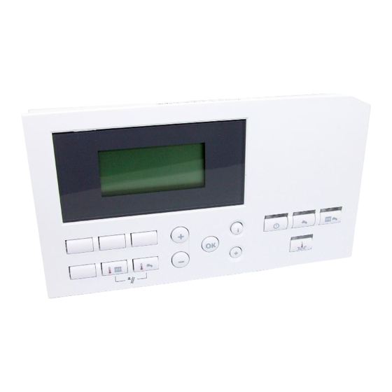
Viessmann Vitotronic 100 HC1 User's Manual And Operating Instructions

Viessmann Vitotronic 100 HC1 User's Manual And Operating Instructions

Vitodens 200-w, wb2b series multi-boiler system with control units for operation with a constant temperature and weather-compensated cascade control unit for operation with natural gas and liquid propane gas
Table of Contents

Advertisement

Operating Instructions
and User's Information Manual
Vitodens 200-W, WB2B Series
Multi-boiler system with control units for operation with a constant
temperature and weather-compensated cascade control unit
For operation with natural gas and liquid propane gas
VITOTRONIC 100, HC1
VITOTRONIC 300-K, MW2S
Certified as a component part
of Viessmann boilers only
5728 417 v1.0 09/2010
Vitotronic 100, HC1
Vitotronic 300-K, MW2S

Advertisement

Table of Contents
loading
Need help?

Need help?

Do you have a question about the Vitotronic 100 HC1 and is the answer not in the manual?

Questions and answers

Summary of Contents for Viessmann Vitotronic 100 HC1

  • Page 1 For operation with natural gas and liquid propane gas VITOTRONIC 100, HC1 VITOTRONIC 300-K, MW2S Vitotronic 100, HC1 Vitotronic 300-K, MW2S Certified as a component part of Viessmann boilers only 5728 417 v1.0 09/2010...
  • Page 2 Safety, Installation and Warranty Requirements Safety, Installation and Warranty Requirements Please ensure that these instructions are read and understood before commencing installation. Failure to comply with the instructions listed below and details printed in this manual can cause product / property damage, severe personal injury, and/or loss of life. Ensure all requirements below are understood and fulfilled (including detailed information found in the manual subsections).
  • Page 3: Table Of Contents

    Table of Contents Page General Information / Safety About these Instructions ............Safety For your Safety .
  • Page 4 Table of Contents Table of Contents Page Scanning Options Scanning Temperatures and Operating Status Information ..........Scanning the Fault Display .
  • Page 5: About These Instructions

    General Information/Safety About these Instructions Take note of all symbols and notations intended to draw attention to potential hazards or important product information. These include ”WARNING”, ”CAUTION”, and ”IMPORTANT”. See below. Warnings draw your attention to the WARNING presence of potential hazards or important product information.
  • Page 6 (if so equipped). Note: CAUTION - Ensure that nothing is obstructing the Viessmann does not test any detectors flow of combustion and ventilation air and makes no representation regarding Should overheating occur or the gas and no chemicals, garbage, gasoline, supply fail to shut off, do not any brand or type of detector.
  • Page 7 Safety For your Safety (continued) Frozen water pipe hazard If your home will be unattended for an extended period of time during cold weather, you should... WARNING Shut off the water supply to the Failure to protect against frozen pipes building, drain the water pipes and add could result in burst water pipes, an antifreeze for potable water to drain...
  • Page 8 Safety For your Safety (continued) If you notice fire coming from the Installation area conditions Sources of combustion and ventilation air appliance, call the fire department contaminants immediately! Do not attempt to extinguish WARNING the fire unless qualified to do so. Areas likely to contain contaminants: Incorrect ambient conditions can lead to New building construction...
  • Page 9: Getting Started

    Inform Yourself Getting Started... The timer of the control unit switches between ”normal room temperature” and ”reduced room temperature” at the required times. 1. Normal room temperature Times and duration of the two room for the times you spend at home and temperatures can be set on the require a comfortably warm room programming unit of your control.
  • Page 10: Overview Of Controls And Indicators

    Inform Yourself Overview of Controls and Indicators You can change all settings of your heating system centrally at the Vitotronic 100 of every boiler and at the Vitotronic 300-K, MW2S. All possible adjustments / settings are described in these operating instructions. You no longer need the individual operating instructions for the Vitotronic 100, HC1.
  • Page 11 Inform Yourself Overview of Controls and Indicators (continued) Vitotronic 100, HC1 A Pressure gauge D Factory default setting B Fault display (red) (see page 38) E User interface C Operating status display (green) F ON / OFF switch (see page 15 and 16) Set boiler water temperature Heating and DHW...
  • Page 12: Opening The Programming Unit

    Inform Yourself Overview of Controls and Indicators (continued) You can change all settings of your heating system centrally at the Vitotronic 100 of every boiler and at the Vitotronic 300-K, MW2S. You may also make such adjustments at the remote control, if your system is equipped with one. Remote control operating instructions.
  • Page 13 Inform Yourself Overview of Controls and Indicators (continued) Emissions test switch (see pg. 14) Heating circuit selector buttons (pg.14) Display window Normal room temperature (pg. 19) Heating programs (pg. 17) Boiler sequence 1-23-4 Control on/off switch (pg. 15) Fuse F1 Energy saving mode (pg.
  • Page 14: Select The Heating Circuit - Before Every Setting And Scanning Operation

    Inform Yourself Overview of Controls and Indicators (continued) Adjustment of the display window Other display symbols (These are not displayed contrast Open the hinged cover on the continuously, but appear according programming unit, and press and, at to system type and operating status) the same time, adjust the contrast with button.
  • Page 15: Starting The Heating System

    Start-up / Shutdown Starting the Heating System 1. Check the heating system pressure at the pressure gauge A. If the system pressure is below 12 psi / 0.8 bar the system pressure is too low. 2. For room air dependent operation: Check whether the ventilation apertures in the boiler room are open and unobstructed.
  • Page 16: Shutting Down The Heating System

    Start-up / Shutdown Shutting Down the Heating System If you do not need to use your heating system temporarily, i.e. during a summer holiday, switch all heating circuits of the Vitotronic 300-K, MW2S to “Standby mode” 9 (see page 17). If you want to shut down only one boiler of your heating system, switch the relevant Vitotronic 100 to “Standby mode”...
  • Page 17: Starting A Heating Circuit And Dhw Heating

    Start-up / Shutdown Starting a Heating Circuit and DHW Heating You want to heat your rooms and have Central heating will be provided with DHW available. normal or reduced room temperature (frost protection) according to the set Press the following keys: time program.
  • Page 18: Starting Dhw Heating Only

    Start-up / Shutdown Starting DHW Heating Only You do not want to heat any rooms, but Central heating is disabled for that you want to make DHW available. heating circuit. DHW heating (if DHW tank is Press the following keys: installed) is enabled and the DHW recirculation pump (if installed) is ON for the required heating...
  • Page 19: Setting A Permanent Room Temperature

    Adjusting the Room Temperature Setting a Permanent Room Temperature Observe the following points if your heating circuit should provide central heating: 1. For the respective heating circuit 3. The timing of when the heating , select “Htg. + DHW” circuit delivers central heating with normal or reduced room temperature Check: depends on the settings of the time...
  • Page 20: Selecting A Reduced Room Temperature

    Adjusting the Room Temperature Setting a Permanent Room Temperature (continued) Selecting the reduced room temperature Press the following: for the required heating for the required temperature. circuit. to confirm; the temperature no longer flashes and is 2. tm for “Red. room temp.”; the saved.
  • Page 21 Adjusting the Room Temperature Setting a Permanent Room Temperature (continued) Selecting the reduced room temperature (continued) to confirm; “Htg. cycle 1 On” will then be displayed. for the heating phase starting point. to confirm; “Htg. cycle 1 Off” will then be displayed. for the heating phase end point.
  • Page 22: Changing The Room Temperature For A Few Days

    Adjusting the Room Temperature Changing the Room Temperature for a Few Days The following energy saving options are available for times when you are not at home: You can switch central heating OFF completely (see “Switching OFF the heating circuit and DHW heating” on page 17) You can set central heating to minimum energy consumption (eg.
  • Page 23: Changing The Room Temperature For A Few Hours Only

    Adjusting the Room Temperature Changing the Room Temperature for a Few Hours Only The following functions enable you to change the room temperature for a few hours, without permanently altering your control settings. To save energy, you can reduce the normal room temperature with “Energy saving mode”...
  • Page 24: Selecting Constant Dhw Heating

    Selecting DHW Heating Selecting Constant DHW Heating Note The control unit is set up so that the setting for DHW heating applies to all heating circuits. If you want to make changes, contact your local heating contractor. Observe the following points if you want 7.
  • Page 25: Selecting A Time Program (Switching Times)

    Selecting DHW Heating Selecting Constant DHW Heating (continued) Setting time programs (switching times) Heating system without DHW recirculation pump Note The control unit is set up so that the setting for DHW heating applies to all heating circuits. If you want to make changes, contact your local heating contractor. DHW heating can be enabled / disabled up to four times per day (four time phases).
  • Page 26: Selecting Automatic Mode (If Required)

    Selecting DHW Heating Selecting Constant DHW Heating (continued) Setting automatic mode (if required) Setting automatic mode (if required) In economy mode, the normal room temperature will be reduced automatically. Press the following keys: for the required heating 3. ⊕/ for “Automatic?”, If circuit.
  • Page 27: Selecting Dhw Heating For A Few Hours Only

    Selecting DHW Heating Selecting Constant DHW Heating (continued) Press the following keys if you want to delete a time phase: for the required heating until “--:--” is displayed for circuit. the end time. 12. uw for “DHW time program”. until the required “DHW cycle Off”...
  • Page 28: Selecting Dhw Heating Only Once

    Selecting DHW Heating Only Once The following function enables you to heat DHW once, without permanently altering your settings. For this, select “Party mode” g. Preconditions: Not in “Standby mode” 9 and not in the “Holiday program” j The DHW temperature must be below the set value (see page 24) for the required heating to confirm;...
  • Page 29: Setting Time And Date

    Further Adjustments Setting Time and Date Date and time are factory-set and may be changed manually. Press the following keys: to confirm; ”Date” is displayed. 1. uý for “Time”. 2. ⊕/ for the required time. 4. ⊕/ for the required date. to confirm.
  • Page 30: Selecting The Boiler Sequence

    Further Adjustments Selecting the Boiler Sequence Actual boiler sequence (standard display) Your contractor has allocated a boiler number to each boiler. The standard display shows the current boiler sequence: H The enabled boilers are indicated in front of the first hyphen. H The boilers listed after the first hyphen are available for heating, but are not currently required.
  • Page 31: Changing The Heating Pattern

    Further Adjustments Changing the Heating Pattern You can alter the heating characteristics if the room temperature does not meet your requirements for some time. You alter the characteristics by changing the slope and shift of the heating curve. For more information regarding the heating curve, see page 33. Observe the modified heating characteristics over several days (if possible, await a major change in the weather) before making further adjustments.
  • Page 32 Further Adjustments Changing the Heating Pattern (continued) Change heating pattern if ... Action Example ... not enough heat is generated in Adjust the slope of the heating curve the cold season upwards by one increment Slope ... too much heat is generated in the Adjust the slope of the heating curve cold season downwards by one increment...
  • Page 33: Modifying The Boiler Heating Characteristics

    Further Adjustments Modifying the Boiler Heating Characteristics The heating curves demonstrates the relationship between the outdoor temperature and the boiler water or common supply temperature. Put simply: the lower the outdoor temperature, the higher the boiler water or supply temperature. The illustrated heating curves apply subject to the following settings: Heating curve shift = 0 Different shift settings offset the curves parallel in a vertical direction.
  • Page 34: Operating Status Information

    Scanning Options Scanning Temperatures and Operating Status Information Subject to the connected components and settings you have made, you can scan the current temperatures and operating conditions. Press the following keys: for “boiler water for further scanning of the list. temperature”.
  • Page 35: Scanning The Fault Display

    Scanning Options Scanning the Fault Display Vitotronic 100, HC1 A Fault display (red) C Fault code B Fault number D Fault symbol If your heating system has developed a fault, it will be displayed and indicated by the flashing red fault indicator A. You can check the fault code on the display by scanning;...
  • Page 36: Scanning Temperatures

    Scanning Options Scanning Temperatures Subject to the connected components and settings you have made, you can scan the current temperatures and operating conditions. To exit the setting mode at any time, press the following keys: for the required heating 3.⊕/ for further scanning of the list.
  • Page 37: Scanning Time Programs

    Scanning Options Scanning Temperatures (continued) Scanning time programs Press the following keys: for the required heating circuit. 12. ur+ for heating and DHW time program 3. uw+ for DHW time program 4. up+ for DHW recirculation pump time program press and hold down simultaneously;...
  • Page 38 Scanning Options Scanning the Fault Display Vitotronic 300-K, MW2S Fault D B G - A Fault display (red) C Fault code B Fault number D Fault symbol If your heating system has developed a fault, it will be displayed and indicated by the flashing red fault indicator A.
  • Page 39: Selecting The Time Programs

    Scanning Options Selecting the Time Programs Rooms are too cold Cause Remedy The heating system is switched OFF, Switch system ON / OFF switch “8” ON (see page 15) ON indicator “8” (green) OFF Switch ON the main power supply to all boilers and Vitotronic 300-K, MW2S, if installed (outside the boiler room) Check the fuse in the Vitotronic 300-K, MW2S (F1) Control unit or remote control incorrectly...
  • Page 40: Rooms Are Too Hot

    Scanning Options Selecting the Time Programs (continued) Rooms are too hot Cause Remedy Control unit control incorrectly adjusted Check and correct settings, if required: The heating circuit must be switched ON Room temperature (see page 19) Time (see page 29) Boiler heating characteristics (see page 31) Faults at the Vitotronic 100: Check the type of fault (see page 38) and notify your local heating con-...
  • Page 41: Off" Is Displayed By The Vitotronic 100

    Scanning Options Selecting the Time Programs (continued) The DHW is too hot Cause Remedy Control unit control incorrectly adjusted Check and correct the DHW temperature, if required (see page 24) Sensor fault Contact your local heating contractor Emissions test switch “S” is set to “h” Set emissions test switch “S”...
  • Page 42: Remote Control" Is Displayed By The Vitotronic 300-K, Mw2S

    Scanning Options Selecting the Time Programs (continued) “Remote control” is displayed by the Vitotronic 300-K, MW2S Cause Remedy A remote control is connected to the heating Make adjustments or carry out scanning at the remote control (see circuit separate operating instructions) ”External control”...
  • Page 43: Service Instructions For Your Heating System

    Service Instructions Service Instructions for Your Heating System Viessmann strongly recommends inspection/service of the boiler and the system by a licensed professional heating contractor once a year. Before the heating season begins, the boiler with its burner(s) and direct vent system should be serviced by a qualified heating contractor.
  • Page 44: Lighting And Operating Instructions

    Additional Information Lighting and Operating Instructions FOR YOUR SAFETY READ BEFORE OPERATING W A R N I N G: If you do not follow these instructions exactly, a fire or explosion may result causing property damage, personal injury or loss of life. A.
  • Page 45 5728 417 v1.0...
  • Page 46 5728 417 v1.0...
  • Page 47 5728 417 v1.0...
  • Page 48 +60 +140 +70 +158 +80 +176 +90 +194 +100 +212 +110 +230 Viessmann Manufacturing Company (U.S.) Inc. Viessmann Manufacturing Company Inc. 45 Access Road 750 McMurray Road Warwick, Rhode Island D 02886 D USA Waterloo, Ontario D N2V 2G5 D Canada Tel.

This manual is also suitable for:

Vitotronic 300-k mw2

Table of Contents