Viessmann VITOTRONIC 100, HC1 Installation And Service Instructions Manual
Digital boiler control unit; outdoor-reset logic digital cascade control
Hide thumbs
Also See for VITOTRONIC 100, HC1:
- User's manual and operating instructions (48 pages) ,
- Operating instructions and user's information manual (48 pages)
Table of Contents
Advertisement
Installation and
Service Instructions
for use by heating contractor
Vitotronic 100, Model HC1
Digital boiler control unit
Vitotronic 300-K, MW2S
Outdoor-reset logic digital cascade control
Panel mount, controls up to 4 Vitodens WB2B boilers
VITOTRONIC 100, HC1
VITOTRONIC 300-K, MW2S
Certified as a component part
of Viessmann boilers only
5727 946 v1.2 11/2011
Vitotronic 100, HC1
Vitotronic 300-K, MW2S
Advertisement
Chapters
Table of Contents
Troubleshooting

Related Manuals for Viessmann VITOTRONIC 100, HC1


Summary of Contents for Viessmann VITOTRONIC 100, HC1
- Page 1 Vitotronic 100, Model HC1 Digital boiler control unit Vitotronic 300-K, MW2S Outdoor-reset logic digital cascade control Panel mount, controls up to 4 Vitodens WB2B boilers VITOTRONIC 100, HC1 VITOTRONIC 300-K, MW2S Vitotronic 100, HC1 Vitotronic 300-K, MW2S Certified as a component part of Viessmann boilers only 5727 946 v1.2 11/2011...
-
Page 2: Safety, Installation And Warranty Requirements
Safety, Installation and Warranty Requirements Please ensure that this manual is read and understood before commencing installation. Failure to comply with the instructions listed below and details printed in this manual can cause product/property damage, severe personal injury, and/or loss of life. Ensure all requirements below are understood and fulfilled (including detailed information found in manual subsections). -
Page 3: Table Of Contents
....................................Service Scanning – Vitotronic 100, HC1 Service level summary . - Page 4 ............................................. . . Product Information Vitotronic 100, HC1, and Vitotronic 300-K Only for integration/installation on Viessmann boilers and for wall mounting. These application examples are only recommendations, and must therefore be checked on site for completeness and function.
-
Page 5: General Information
Vitotronic 300-K: ultimate owner where the literature - Installation & Service Instructions can be found. Contact Viessmann for - Operating & User Instructions additional copies. - Instructions of other Viessmann products utilized and installed... -
Page 6: About These Instructions
National Codes. Viessmann recommends the installation of a disconnect switch to the 120 VAC power supply outside of the boiler room. The installer must provide... -
Page 7: Heating System Designs
Heating System Designs System design A Vitodens 200-W (models 45 to 105) with the Vitotronic 100, HC1, with KMK cascade communication module as part of the standard delivery B Vitotronic 300-K with LON communication module (accessory) C DHW cylinder D Vitotronic 200-H with LON... - Page 8 System design (continued) The codes must be set on every Vitotronic 100. (see section on coding page 82) Vitotronic 100, HC1 Required coding 01 : 2 Multi-boiler system with Vitocontrol-S, WB2B Setting the boiler number at the Vitotronic 100 of the...
- Page 9 Low-Loss Header Fig. 31 When designing a multiple Vitodens system as shown above, please reference applicable multiple Vitodens technical documentation, and contact your local Viessmann Sales Representative for further assistance. IMPORTANT WARNING When extending wire, there is the This installation example depicts a...
-
Page 10: Installation - Vitotronic 300-K
Installation – Vitotronic 300-K Installing the Cascade Communication Module A The cascade communication module Installation Instructions shipped with boiler. A Vitotronic 300-K 1 2 3 4 1 2 3 4 B KMK-BUS KMK1 KMK2 KMK1 KMK2 C Boiler control with Vitotronic 100 and KMK Module (max 4 boilers) D 2-core Cable (cable cross-section 2 x 0.5 mm... -
Page 11: Summary Of Electrical Connections (Power Pump Module)
Installation – Vitotronic 300-K Summary of electrical connections (Power Pump Module) Installation Instructions, Power Pump Power/Pump module Module MAIN POWER SUPPLY 120V, 60HZ, 12A MAIN DISCONNECT SWITCH 120/230 Transformer 1 2 3 1 2 3 1 2 3 120VAC L1 G N L G N WALL RECEPTACLE... - Page 12 Installation – Vitotronic 300-K Summary of electrical connections (Power Pump Module) (continued)
-
Page 13: Installing Modules
Installation – Vitotronic 300-K Installing modules 1. Install the modules in accordance with the layout indicated on DIN rail inside the control panel. 2. Connect the modules in accordance with the overview on page 14 and 15, using the connecting cables provided. A1 Power supply module A2 Cascade electronic module A3 Power module... -
Page 14: Summary Of Electrical Connections
Installation – Vitotronic 300-K Summary of electrical connections F1 4A (slow) - Page 15 Installation – Vitotronic 300-K Summary of electrical connections (continued)
- Page 16 Installation – Vitotronic 300-K Summary of electrical connections (continued) A1 Power supply module A3 Power module fÖ sÖA1 Heating circuit pump or Power supply connection DHW tank loading system DHW tank pump (accessories) DHW re-circulation pump A2 Cascade electronic module Outdoor temperature sensor Shunt or supply pump gÖ...
-
Page 17: Sensor Connection
Installation – Vitotronic 300-K Sensor connection Outdoor temperature sensor The outdoor temperature sensor should be mounted 6.5 to 8ft / 2 to 2.5m above ground level on the north or north-west facing wall of the building. In the case of multi-storey buildings, it should be mounted in the upper half of the second storey. - Page 18 Installation – Vitotronic 300-K Sensor connection (continued) DHW tank temperature sensor The sensor measures the domestic hot Heating systems with domestic hot Check the sensor 1. Disconnect wires from terminals water tank temperature. water heating (single-boiler systems X2.7 and 2.1 of module A2. only) 1.
-
Page 19: Connection Of The Pumps
Installation – Vitotronic 300-K Connection of the pumps Available pump connections sÖ Heating circuit high temperature (without mixing valve) sÖM2 Heating circuit M2 pump Terminals 2 - L, - G , - N sÖM3 Heating circuit M3 pump Terminals 1 - L, - G , - N DHW pump for heating up the domestic hot water tank - Terminals 4 - L, - G , - N... -
Page 20: Connection To Modulating Valve Actuators
Installation – Vitotronic 300-K Connection of modulating valve actuators Control unit 1 120V or 24V valve adaptor 1 120V valve adaptor 1 24V valve adaptor 2 DIN rail in connection enclosure 2 120V valve actuator 2 24V valve actuator 3 aBH Terminals 1. -
Page 21: Connection Of External Contacts
Installation – Vitotronic 300-K Connection of external contacts A External heating program WARNING changeover or “Mixing valve open” Heating circuits are no longer frost Contact closed: protected during mixing valve closed. The manually pre-selected heating A minimum boiler return temperature program can be changed via this is not maintained during external contact, (see table below) enabling the... -
Page 22: Connection To Compiled Failure Alarm
Installation – Vitotronic 300-K Connection of the compiled failure alarm Implement connection gÖ on A3 in Rated voltage: 120 VAC 60 Hz accordance with overview on page 104 Rated current: max. 2 FLA and control panel wiring. Recommended connection wire size: AWG 14 1. -
Page 23: Making The Lon Connection
Installation – Vitotronic 300-K Making the LON connection The Viessmann LON system is designed for the Line BUS topology with end of line resistors on both ends. Connection with Viessmann LON cable 23ft. / 7m 23ft. / 7m A Control unit or Vitocom... -
Page 24: Power Supply
23ft. / 7m max. 900 m / 3000 ft. A Control unit or Vitocom Note: B LON cable The Viessmann LON system always C End of line resistor (standard requires two conductors and shielding. delivery of Vitotronic 300-K) Conductors are interchangeable. -
Page 25: Initial Start-Up
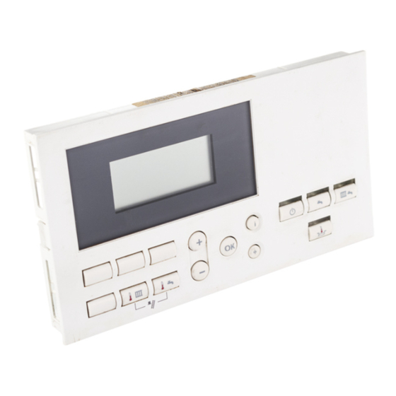
2. Controls and display elements H Vitotronic 100, HC1 ...................................... -
Page 26: Further Step-By-Step Instructions
Initial start-up Further step-by-step instructions Commissioning of all Vitodens 200-W, WB2B with Vitotronic 100, HC1 Service Instructions Vitodens 200-W, WB2B ºC – A Heating programs D Fact0ory default setting G No function B No function E Confirmation H Emissions test function... -
Page 27: Checking The Heating Circuit Allocation (Vitotronic 300-K)
Initial start-up Further step-by-step instructions (continued) Boiler sequence A Heating circuit selection G Heating and DHW O Adjusting values B Reduced room temperature H Economy mode P Time programs C DHW temperature K Party mode R Holiday program D Normal room temperature L Information S Time/date E Standby mode... -
Page 28: Configuring A Multi-Boiler System
Example of a multi-boiler system Vitotronic 100 Vitotronic 100 Vitotronic 300-K KMK1 KMK2 KMK1 Vitotronic 300-K Vitotronic 100, HC1 – – – – Vitotronic 300-K Multi-boiler system Multi-boiler system –– – – – – Set code ”01:2” Set code ”01:2”... -
Page 29: Updating The Lon Participant List On Vitotronic 300-K
Initial start-up Further step-by-step instructions (continued) Update the LON participant list on Vitotronic 300-K Only possible if all users are connected and the control unit is encoded as fault manager (coding 79 : 1 factory default setting) Note: In each heating system, only one Vitotronic may be encoded as fault manager. Press w and simultaneously Press D. -
Page 30: Reducing The Maximum Burner Output (Vitotronic 100)
Central control Control type Detached house or apartment Control strategy building (management system) LON participant number Viessmann system number DHW priority Monitoring LON participants Heating circuit pump logic function (economy control) Minimum supply temperature limit, heating circuits Maximum supply temperature... -
Page 31: Checking Outputs (Actuators) And Sensors
Initial start-up Further step-by-step instructions (continued) Checking outputs (actuators) and sensors Vitotronic 100 Relay test 1. Press 9 and simultaneously for 2. Select the relay outputs 3. Press approx. two seconds. with The following relay outputs may be selected: Display Relay function indication Burner modulation lower output... -
Page 32: Selecting The Boiler Sequence (Vitotronic 300-K)
Initial start-up Further step-by-step instructions (continued) Vitotronic 300-K Relay test 1. Press 9 and simultaneously for 2. Select the relay outputs 3. Press approx. two seconds. with The following relay outputs may be selected: Output 20M1 ON Mixing valve (M2) open Note: Output 52A1 open Mixing valve (M2) close... -
Page 33: Adjusting The Heating Curve (Vitotronic 300-K)
Initial start-up Further step-by-step instructions (continued) Adjusting the heating curve (Vitotronic 300-K) The heating curves illustrate the relationship between the outdoor temperature and the boiler water or the supply temperature. To put it simply: the lower the outdoor temperature, the higher the boiler water or supply temperature. The room temperature again depends on the boiler water or the supply temperature. - Page 34 Initial start-up Further step-by-step instructions (continued) Changing slope and shift (for every heating circuit separately) 1. Call up slope with 2. Change the value with adjustable value 0.2 to 3.5; call up shift with 3. Confirm the set value with adjustable value 8.6 to 104°F / –13 to +40°C.
- Page 35 Initial start-up Further step-by-step instructions (continued) Adjusting the normal room temperature (for every heating circuit separately) The value will be automatically Normal room temperature: Select the normal day temperature with transferred after approx. 2 seconds. Standard room temp. the set value adjuster. Reduced room temperature: Reduced room temp.
-
Page 36: Service Scanning - Vitotronic 100, Hc1
Service scanning – Vitotronic 100, HC1 Service level summary Function Entry Exit Page Reducing the max. Press 9 and tw Press “OK” burner output simultaneously for approx. 2 seconds Relay test Press 9 and “OK” Press “OK” simultaneously for approx. 2 seconds... -
Page 37: Temperatures, Boiler Coding Card And Quick Scans
Service scanning – Vitotronic 100, HC1 Temperatures, boiler coding card and quick scans 1. Press 9 and rw simultaneously 2. Select the required scan for approx. two seconds. with Brief scans System Control unit software version Programming unit software design 1... -
Page 38: Scanning Operating Conditions
Service scanning – Vitotronic 100, HC1 Scanning operating conditions 1. Press 8. 2. Select the required operating 3. Press condition scan with Scans Display Explanation Notes indication 0 01 Boiler number –– 3__65 °C Boiler temperature –– 263572 Burner hours run The hours run can be reset to 0 with D. -
Page 39: Scanning And Resetting Service Displays
Service scanning – Vitotronic 100, HC1 Scanning and resetting service displays After the limits set up via coding addresses 21 and 23 (see page 80) have been reached, the programming unit display flashes one of the following messages. Note: Set code 24:1 and then code 24:0, if maintenance is implemented before a maintenance message is displayed; the set maintenance parameters for hours run and maintenance intervals are then reset to 0. -
Page 40: Service Scanning - Vitotronic 300-K
Service scanning – Vitotronic 300-K Service level summary Function Entry Exit Page Adjusting display Press the “OK” and “+” –– –– contrast buttons simultaneously; the display will darken Press the “OK” and “-” buttons –– –– simultaneously; the display will get lighter Participant check Press the w and “OK”... -
Page 41: Temperatures And Quick Scans
Service scanning – Vitotronic 300-K Temperatures and quick scans 1. Press 9 and rw simultaneously 3. Press “OK”. for approx. 2 seconds. 2. Select the required scan with The following values can be scanned subject to the actual equipment level: Outdoor temperature adjusted The adjusted outdoor temperature Outdoor temperature actual... - Page 42 Scan Scan Display acc. to Number of KM system designs (s s ee coding address 00) participants Software version Software version Software version Software version control unit programming mixing valve mixing valve Software version unit extension M2 extension M3 remote control Printed Circuit Printed Circuit mixing valve...
-
Page 43: Scanning Operating Conditions
Service scanning – Vitotronic 300-K Scanning operating conditions 1. Press 3. Press 2. Select the required scan with The following values can be scanned subject to the actual equipment level: Participant number If a holiday program has been entered A fault can be acknowledged with Holiday program with departure and “OK”. -
Page 44: Troubleshooting - Vitotronic 100, Hc1
Troubleshooting – Vitotronic 100, HC1 Retrieving fault codes from the fault memory (fault history) The most recent 10 faults are saved and may be called up. Faults are sorted by date. The most recent fault is fault number 1. 1. Press rw and simultaneously for approx. - Page 45 Troubleshooting – Vitotronic 100, HC1 Faults displayed at the programming unit (continued) Fault Cause Remedy System characteristics code 0 0 0 0 f f f f Control mode Service “0F” is only displayed in the Service the equipment. fault history...
- Page 46 Troubleshooting – Vitotronic 100, HC1 Faults displayed at the programming unit (continued) Fault Cause Remedy System characteristics code eb b b b Burner blocked Boiler control initiated a combustion - Heat generated by boiler must be calibration but could not complete...
- Page 47 Troubleshooting – Vitotronic 100, HC1 Faults displayed at the programming unit (continued) Fault Cause Remedy System characteristics code f f f f 4 4 4 4 Burner in a fault mode No flame signal is present. Check ionization electrode and...
-
Page 48: Troubleshooting - Vitotronic 300-K
Troubleshooting – Vitotronic 300-K Retrieving fault codes from the fault memory (fault history) The most recent 10 faults are saved and may be called up. Faults are sorted by date. The most recent fault is fault number 1. 1. Press rw and simultaneously Fault history for approx. - Page 49 Troubleshooting – Vitotronic 300-K Faults displayed at the programming unit (continued) Fault display in plain text Calling up acknowledged fault Ext. fault messages Outdoor temperature sensor Press for approx. 2 seconds. The Supply sensor fault will then be displayed. DHW tank sensor (1 or 2; display Select the acknowledged fault only, if a second DHW tank with...
- Page 50 Troubleshooting – Vitotronic 300-K Faults displayed at the programming unit (continued) Fault Cause Remedy System characteristics code 5 5 5 5 0 0 0 0 DHW tank primary pump ON: DHW tank temperature sensor 1 Check DHW tank temp. sensor Set DHW temp.= set boiler water shorted out temp., priority controls are cancelled...
- Page 51 Troubleshooting – Vitotronic 300-K Faults displayed at the programming unit (continued) Fault Cause Remedy System characteristics code 9 9 9 9 2 2 2 2 Collector temp. sensor shorted out, Control mode Check solar control unit sensor Only solar control unit fault codes Only solar control unit fault codes connects to S1 at the Vitosolic will be displayed...
- Page 52 Troubleshooting – Vitotronic 300-K Faults displayed at the programming unit (continued) Fault Cause Remedy System characteristics code c c c c 2 2 2 2 Cable break KM BUS to solar Check KM BUS cable and the solar Control mode control unit.
- Page 53 Troubleshooting – Vitotronic 300-K Faults displayed at the programming unit (continued) LON participants fault messages Participant Preconditions: 1 1 1 1 2 2 2 2 The control unit must be programmed as fault manager (code “79:1”) Fault Cause Remedy System characteristics code 0 0 0 0 1 1 1 1 Control mode...
-
Page 54: Function Description - Vitotronic 100, Hc1
Function description – Vitotronic 100, HC1 Boiler temperature control Brief description The boiler water temperature is Coding addresses which influence the regulated by controlling a modulating boiler temperature control burner. 06 (see page 80). The set boiler water temperature For a description, see the coding set-point is controlled by Vitotronic overview. -
Page 55: Function Description - Vitotronic 300-K
This value must be set no higher than the set DHW temperature and the lowest value of coding address 06 external demands (e.g. the set of all connected Vitotronic 100, HC1. supply temperature defaulted by coding address 9b or via the Input Lower control range limit Module 0 to 10 V). - Page 56 Function description – Vitotronic 300-K Cascade control (continued) Control sequence Stand-alone type of control: Parallel boiler control (coding 3b : 0 without supply temperature sensor or coding 3b : 1 with supply temperature sensor) The cascade control unit defaults the Without supply temperature sensor: set boiler water temperature to all The control deviation is calculated from...
- Page 57 Function description – Vitotronic 300-K Cascade control (continued) Net calorific strategy 1 Conventional boilers are preferably Benefit: operated at their upper output range, to As few boilers as possible are active. reliably prevent the formation of condensate due to low return temperatures.
- Page 58 Function description – Vitotronic 300-K Cascade control (continued) Control strategy example Two boiler system with modulating burners and separate flue gas systems: Boiler 1: 100% rated output (basic load set to 25%) Boiler 2: 100% rated output (basic load set to 25%) Gross calorific strategy (coding 3C: 0) Start-up Switching OFF...
- Page 59 Function description – Vitotronic 300-K Cascade control (continued) Net calorific strategy 2 (coding 3C: 2) Start-up Switching OFF Time Time Boiler sequence The boiler sequence is determined by Boiler 1, 2, 3 or 4 permanent lead the boiler sequence selection and the boiler.
-
Page 60: Heating Circuit Control
Function description – Vitotronic 300-K Heating circuit control Time program Brief description The control unit timer changes in The control unit provides control accordance with the times programmed circuits for one high temperature in the room heating and DHW heating (boiler) circuit and two mixing valve program between the heating with circuits. - Page 61 Function description – Vitotronic 300-K Heating circuit control (continued) Domestic hot water temperature Heating circuit pump logic System dynamics – mixing valve circuit With priority control: (only in conjunction with a mixing valve (economy circuit) The set supply temperature will be The heating circuit pump is switched circuit) set to 32˚F / 0˚C during DHW...
- Page 62 Function description – Vitotronic 300-K Heating circuit control (continued) Supply temperature control Differential temperature: The differential temperature may be adjusted via coding address 9F; factory supplied setting 15˚F / 8˚C. The differential temperature is that minimum temperature differential by which the common supply temperature should be higher than the currently required supply temperature of the mixing valve circuit.
-
Page 63: Dhw Tank Temperature Control
Function description – Vitotronic 300-K DHW tank temperature control Brief description The DHW tank control logic is a During DHW tank heating, a constant Coding addresses which influence the set-point control. It is the result of boiler supply temperature will be set DHW tank control starting and stopping the DHW pump. - Page 64 Function description – Vitotronic 300-K DHW tank temperature control (continued) Control sequence Pump delay Coding 55: 1: Coding 55: 3: The DHW pump continuous operation Adaptive DHW tank heating DHW tank control – DHW heating (for (coding 62: 10) after the DHW tank DHW loading systems only) heating, until: With adaptive DHW tank heating, the...
-
Page 65: Components - Vitotronic 300-K
Components – Vitotronic 300-K Components from the parts list The main PCB comprises: Mixing valve extension Optolink / override test switch supplementary PCB Relays and outputs for controlling . pumps and actuators. This is plugged into the mixing valve The PCB comprises: Slot for power supply unit. - Page 66 Components – Vitotronic 300-K Components from the parts list (continued) DHW tank temperature sensor 3. Compare measurement with the Connection See page 19. actual temperature displayed (for scanning, see page 41). Check the installation and replace Check sensor 1. Remove wire from terminal X2.7. sensor, if necessary, in case of severe deviation.
- Page 67 Components – Vitotronic 300-K Components from the parts list (continued) Outdoor temperature sensor Connection See page 16. Check sensor 1. Remove wire from terminal X2.2. 2. Check the sensor resistance at terminals 1 and 2 of the plug. Outdoor Resistance temperature in in Ω...
- Page 68 Components – Vitotronic 300-K Fuse F1 T4 A, 250V Max. power loss 1.6W A1 Power supply module...
-
Page 69: Mixing Valve Circuit Extension Kit
Components – Vitotronic 300-K Mixing valve circuit extension kit Mixing valve motor A Plug in the mixing valve motor | Mixing valve motor open ~ Mixing valve motor close B Connect to X1 or X3 on the A4 module Changing the rotational direction Specification Remove the cover and reinsert 3-pole Rated voltage:... -
Page 70: Installation Examples
Components – Vitotronic 300-K Installation examples Mixing valve insert conversion (if required), see mixing valve installation instructions. Factory supplied Mixing valve motor rotational direction Change the mixing valve motor rotational direction for these installation examples KV Boiler supply HR Heating return HV Heating supply... -
Page 71: Remote Control
Components – Vitotronic 300-K Remote control Vitotrol 200 (with integral room temperature sensor for room temperature feed-back in conjunction with a mixing valve circuit) Setting of: Day temperature Heating program Economy and party mode Function changes can be made via coding addresses A0, b0 to b9, C0 to C2, E1, E2 (see coding overview). Connection 2-wire cable 164ft. - Page 72 Components – Vitotronic 300-K Remote control (continued) Specification Power supply via KM BUS. Safety class: Protection: IP 30 Permiss. ambient temperature During operation: 32 to 104˚F 0 to +40˚C 1 2 3 4 In storage and transport: –4 to +149˚F –20 to +65˚C D Printed circuit board DIP switches Set room temperature...
- Page 73 Components – Vitotronic 300-K Remote control (continued) Vitotrol 300 (with integral room temperature sensor for room temperature feed-back in conjunction with a mixing valve circuit) Setting of: Normal and reduced temperature Domestic hot water temperature Heating program Holiday program Switching times Economy and party mode Function changes can be made via coding addresses A0, b0 to b9, C0 to C2, E1, E2 and F2 (see coding overview).
- Page 74 Components – Vitotronic 300-K Remote control (continued) Specification Power supply via KM BUS. Safety class: 3 2 1 int. ext. Protection: IP 30 Permiss. ambient temperature: In use: 32 to 104˚F 0 to +40˚C In storage and transport: A PCB DIP switches (back of the –4 to+149˚F remote control) –20 to +65˚C...
- Page 75 Components – Vitotronic 300-K Remote control (continued) Connecting several remote control units When connecting several remote controls to the control unit, install a terminal box on site. Version 1 max. max. max. 50ft. / 15m 50ft. / 15m 50ft. / 15m A To control unit A2 terminal aVG On-site connection via terminal box: B Terminal box (on site)
- Page 76 Components – Vitotronic 300-K Remote control (continued) Version 2 max. 50ft. / 15m max. 50ft. / 15m max. 50ft. / 15m A To control unit A2 terminal aVG If several remote control units and B Terminal box (on site) additional KM BUS participants are C Vitotrol 200/300 connected, make the connections via D Vitotrol 200/300...
-
Page 77: Room Temperature Sensor
Components – Vitotronic 300-K Room temperature sensor The room temperature sensor measures the actual room temperature, if the remote Vitotrol unit cannot be installed in a suitable location. Connection See page 71 to 76. Check sensor 1. Disconnect the wires from the sensor. -
Page 78: Input Module 0 To 10 V
Components – Vitotronic 300-K Input Module 0 to 10 V For external control of the boiler/supply temperature via a 0 to 10VDC signal 30 to 120˚C or 10 to 100˚C (86 to 248˚F or 50 to 212˚F) to signal reduced mode and regulate a heating circuit pump to a lower speed. Electronics 50mA (slow) -
Page 79: Coding - Vitotronic 100, Hc1
Coding – Vitotronic 100, HC1 Resetting codings to the factory setting 1. Press w and rw simultaneously for approx. two seconds, until the first two arrows appear in the display. 2. Press D. Coding Level 1 Calling up coding level 1 1. -
Page 80: Coding Level 2
Coding – Vitotronic 100, HC1 Coding Level 2 Calling up coding level 2 1. Press “w” and “rw” 3. Press “ ” for the required ” to confirm. The display briefly 6. “ simultaneously for approx. 2 coding address, the address flashes. - Page 81 Coding – Vitotronic 100, HC1 Coding 2 (continued) Coding (factory default setting) Possible change Boiler 2F: 1 Air bleed program enabled 2F: 0 2F: 0 Air bleed program/fill program disabled Air bleed program/fill program disabled 2F: 2 Filling program enabled...
-
Page 82: Coding - Vitotronic 300-K Resetting Codings To The Factory Setting
Coding – Vitotronic 300-K Resetting codes into the factory setting 1. Press w and rw simultaneously 2. Press D. for approx. 2 seconds. Confirm “Base setting? Yes” with Select “Base setting? Yes” or “Base setting? No” with Coding Level 1 Calling up coding level 1 1. - Page 83 Coding – Vitotronic 300-K Coding Level 1 (continued) Coding (factory default setting) Possible change Multi-boiler control unit 36: 0 Electronic minimum system supply temperature 36: 1 Electronic minimum system supply temperature limit set to 32˚F / 0˚C limit adjustable from 32 to 261˚F / 0 to 127˚C 36:127 37: 80 Electronic maximum system supply temperature...
- Page 84 Coding – Vitotronic 300-K Coding Level 1 (continued) Coding (factory default setting) Possible change General (continued) 77: 5 LON participant number 77: 1 LON participant number, adjustable from 1 to 99 Note: 77: 99 Allocate each number only once. DHW priority A1/M2/M3 A0: 0 Without remote control A0: 1 With Vitotrol 200...
-
Page 85: Coding Level 2
Coding – Vitotronic 300-K Coding Level 2 The summary from page 86 lists all possible coding addresses. The coding addresses are grouped in accordance with the adjacent System design sequence. Cod. 00 Multi-boiler control unit Cod. 35 to 49 General Cod. - Page 86 Coding – Vitotronic 300-K Coding Level 2 (continued) Overall summary Coding (factory default setting) Possible change System design 00: 1 See page 82 Multi-boiler control unit 35: 4 4 boilers connected to Vitotronic 300-K 35: 2 2 to 3 boilers connected to Vitotronic 300-K 35: 3 36: 0 Electronic minimum system supply temperature limit...
- Page 87 Coding – Vitotronic 300-K Coding Level 2 (continued) Coding (factory default setting) Possible change General 41: 31 No ECO threshold boiler 1 41:–30 ECO threshold boiler 1 adjustable from –22 to +86˚F / –30 to +30˚C 41:+30 42: 31 No ECO threshold boiler 2 42:–30 ECO threshold boiler 2 adjustable from –22 to +86˚F / –30 to +30˚C...
- Page 88 Coding – Vitotronic 300-K Coding Level 2 (continued) Coding (factory default setting) Possible change Multi-boiler control (continued) DHW (continued) 55: 0 DHW heating, 55: 1 Adaptive DHW heating active (speed of differential ± 4.5˚F / 2.5˚C temperature rise for DHW tank temperature is taken into account during DHW heating) 55: 2 DHW tank temperature control with 2 DHW tank...
- Page 89 Coding – Vitotronic 300-K Coding Level 2 (continued) Coding (factory default setting) Possible change DHW (continued) 66: 4 66: 0 At programming unit Input of set DHW value: Input of set DHW value: At programming unit and all installed At programming unit and all installed 66: 1 At programming unit and remote control –...
- Page 90 Coding – Vitotronic 300-K Coding Level 2 (continued) Coding (factory default setting) Possible change General 76: 0 Without LON communication module 76: 1 With LON communication module; will be recognized automatically 77: 5 LON participant number 77: 1 LON participant number, adjustable from 1 to 99 Note: 77: 99 Allocate each number only once...
- Page 91 The control unit receives the outdoor temperature connected Vitotronic 200-H via LON BUS 98: 1 Viessmann system number 98: 1 System number adjustable from 1 to 5 (in conjunction with monitoring several systems within one LON system with Vitocom 300)
- Page 92 Coding – Vitotronic 300-K Coding Level 2 (continued) Coding (factory default setting) Possible change General (continued) Connection to terminals 2 and 3 in plug aVD 99: 1 Contact affects: 99: 0 (External disable/external mixing valve close) (External disable/external mixing valve close) No function inactive inactive...
- Page 93 Coding – Vitotronic 300-K Coding Level 2 (continued) Coding (factory default setting) Possible change General (continued) 9b: 0 No default set value 9b: 70 Set point temperature for external demand 9b: 70 Set point temperature for external demand (input aVH) 158˚F / 70˚C (input aVH) 158˚F / 70˚C 9b: 1 Set value adjustable from 34 to 261˚F /...
- Page 94 Coding – Vitotronic 300-K Coding Level 2 (continued) Coding (factory default setting) Possible change System circuit/mixing valve circuit (continued) A4: 0 With frost protection A4: 1 No frost protection Adjustment only possible if coding A3: –9 is set. Note: Please observe note regarding coding address A3.
- Page 95 Coding – Vitotronic 300-K Coding Level 2 (continued) Coding (factory default setting) Possible change Systems/mixing valve circuit (continued) b0: 1 Heating mode: b0: 0 With remote control: Heating mode/ reduced mode: With outdoor reset Reduced mode: With outdoor reset With room temperature feed-back b0: 2 Heating mode: With room temperature feed-back...
- Page 96 Coding – Vitotronic 300-K Coding Level 2 (continued) Coding (factory default setting) Possible change Systems/mixing valve circuit (continued) b7: 0 With remote control unit and for heating circuit, b7: 1 With start-up optimization: operation with room temperature feed-back must Max. offset be programmed: 2 hours 30 minutes Without start-up optimization...
- Page 97 Coding – Vitotronic 300-K Coding Level 2 (continued) Coding (factory default setting) Possible change System circuit/mixing valve circuit (continued) C8:31* With remote control unit and for heating circuit, C8: 1 Room influence limit adjustable from 1 to 30 K (1.8 operation with room temperature feed-back must to 54 Fahrenheit degrees) be programmed:...
- Page 98 Coding – Vitotronic 300-K Coding Level 2 (continued) Coding (factory default setting) Possible change System circuit/mixing valve circuit (continued) F8:+10 Temperature limit adjustable from +50 to –76˚F / F8: –5 Temperature limit for terminating the reduced mode 23˚F / – 5 ˚C see example on page 99. +10 to –60˚C F8: –60 Observe the setting of coding address “A3”.
- Page 99 Coding – Vitotronic 300-K Coding Level 2 (continued) Example 1 (”F8: –5“, “F9: –14”) Outdoor temperature in °C Example (using factory default settings) A Set standard room temperature 68°F / 20°C B Set reduced room temperature 37°F / 3°C C Temperature limit 7°F / – 14 °C in accordance with coding address “F9”...
- Page 100 Coding – Vitotronic 300-K Coding Level 2 (continued) Example 2 (”FA: 20“, “Fb: 30”) During the transition from operation with reduced room temperature to operation with standard room temperature, the boiler water or supply temperature will be raised in accordance with the selected heating curve. The boiler water or supply temperature can be automatically increased.
-
Page 101: Slab Curing Function Diagram
Coding – Vitotronic 300-K Slab curing function diagram Coding, see page 97. Temperature-time profile 1 (coding F1: 1) (See back of manual for temperature conversion chart) Days Temperature-time profile 2 (coding F1: 2) Days Temperature-time profile 3 (coding F1: 3) Days Temperature-time profile 4 (coding F1: 4) Days... -
Page 102: Connection And Wiring Diagrams - Vitotronic 100, Hc1
Connection and Wiring Diagrams - Vitotronic 100, HC1 Boiler control, Power Pump Module (models 45,60) wiring diagram 99 C 210 F X1 X2 INTERNAL CONNECTIONS X8.1 X8.10 X8.11 X9.1 GC130 BURNER IGNITION MODULE X9.3 X9.4 WARNING! DISCONNECT POWER BEFORE SERVICING BOILER. - Page 103 Connection and Wiring Diagrams- Vitotronic 100, HC1 Boiler control, Power Pump Module (models 45,60) wiring diagram (continued) Legend A1 Main PCB (GC130 Ignition Module) Boiler Water Temperature Sensor Power Supply Accessory (Not Used) Ionization Electrode A2 Internal Power Supply Unit...
-
Page 104: Boiler Control, Power Pump Module (Models 80,105) Wiring Diagram
Connection and Wiring Diagrams- Vitotronic 100, HC1 Boiler control, Power Pump Module (models 80,105) wiring diagram 99 C 210 F 190A X1 X2 INTERNAL CONNECTIONS X8.1 X8.10 X8.11 X9.1 GC131 BURNER IGNITION MODULE X9.3 X9.4 WARNING! DISCONNECT POWER BEFORE SERVICING BOILER. - Page 105 Connection and Wiring Diagrams- Vitotronic 100, HC1 Boiler control, Power Pump Module (models 80,105) wiring diagram (continued) Legend A1 Main PCB (GC130 Ignition Module) Boiler Water Temperature Sensor Power Supply Accessory (Not Used) Ionization Electrode A2 Internal Power Supply Unit...
-
Page 106: Appendix
Appendix Specification – Vitotronic 100 Rated voltage: 120VAC Rated frequency: 60 Hz Rated current: 2 x 6A~ Power consumption: Safety class: Protection: IP 24 D to EN 60529, safeguard through design and installation Function: Type 1B to EN 60730-1 Permissible ambient temperature: During operation: 32 to 104˚F 0 to 40˚C... -
Page 107: 102 Parts List
7248236 Ordering Replacement Parts: Please provide Model No. from rating plate when ordering replacement parts. Order replacement components from your Viessmann distributor. Parts 001 Module for power supply 002 Module for control software 004 Module for switching relays 005 Module for heating... - Page 108 +176 +194 +100 +212 +110 +230 Viessmann Manufacturing Company (U.S.) Inc. Viessmann Manufacturing Company Inc. 45 Access Road 750 McMurray Road Warwick, Rhode Island D 02886 D USA Waterloo, Ontario D N2V 2G5 D Canada Tel. (401) 732-0667 D Fax (401) 732-0590 Tel.
Need help?
Do you have a question about the VITOTRONIC 100, HC1 and is the answer not in the manual?
Questions and answers