Viessmann VITOTRONIC 100 Installation And Service Instructions Manual
Hide thumbs
Also See for VITOTRONIC 100:
- Installation and service instructions manual (168 pages) ,
- Operating instructions manual (64 pages) ,
- Operating instructions for the system user (57 pages)

Related Manuals for Viessmann VITOTRONIC 100


Summary of Contents for Viessmann VITOTRONIC 100
- Page 1 VIESMANN Installation and service instructions for contractors Vitotronic 100 Type KC2 Electronic boiler control unit For applicability, see the last page VITOTRONIC 100 Please keep safe. 5862 698 GB 02/2005...
-
Page 2: Safety Instructions
Safety instructions Safety instructions Please follow these safety instructions closely to prevent accidents and material losses. Safety instructions explained the Code of Practice of relevant trade associations, Danger all current safety regulations as This symbol warns against the defined by DIN, EN, DVGW, TRGI, risk of injury. - Page 3 Instal- charge static loads. ling non-authorised compo- nents and non-approved modifications/conversion can compromise safety and may invalidate our warranty. For replacements, use only ori- ginal spare parts from Viessmann or those which are approved by Viessmann.
-
Page 4: Table Of Contents
Index Index Installation instructions Preparing for installation Heating system design................Installation sequence Summary of electrical connections .............. Inserting cables and applying strain relief............ Changing the high limit safety cut-out setting (if required) ......Changing the control thermostat setting (if required)........10 Inserting the boiler coding card .............. - Page 5 Index Index (cont.) Coding Calling up coding levels ................37 Resetting codes to the delivered condition ..........37 Coding summary..................37 Burner switching hysteresis ................ 41 Designs Connection and wiring diagram ..............43 Components Room thermostat Vitotrol 100, type UTD ............. 45 Boiler coding card ..................
-
Page 6: Heating System Design
Preparing for installation Heating system design System version One directly connected heating circuit without mixer A Boiler with Vitotronic 100 Cylinder primary pump (acces- B DHW cylinder sories) C Heating circuit without mixer fÖ Power supply (230 V/50 Hz) Burner stage 1 Plug lÖ... - Page 7 Installation sequence Summary of electrical connections Plug 230 V~ When connecting external switching sÖ Heating circuit pump (acces- contacts or components to the low sories) voltage circuit of the control unit, sA Cylinder primary pump (acces- please observe the safety require- sories) ments of protection class II, i.e.
-
Page 8: Inserting Cables And Applying Strain Relief
Installation sequence Inserting cables and applying strain relief Note Blank off unnecessary knockouts in the lower part of the control unit with cable grommets (not cut out). -
Page 9: Changing The High Limit Safety Cut-Out Setting (If Required)
Installation sequence Changing the high limit safety cut-out setting (if required) Adjustment to 100 °C (EGO and JUMO) The high limit safety cut-out is set to 110 °C in the delivered condition. Note This EGO setting change is irreversible! When adjusting the temperature to 100 °C, do not adjust the control thermostat above 75 °C. -
Page 10: Changing The Control Thermostat Setting (If Required)
Installation sequence Changing the high limit safety cut-out setting (if . . . (cont.) Note When adjusting the temperature to 100 °C, do not adjust the control thermostat above 75 °C. Changing the control thermostat setting (if required) Adjustment to 87 °C/ 95 °C The control thermostat is supplied with a factory setting of 75 °C. - Page 11 Installation sequence Changing the control thermostat setting (if . . . (cont.) 1. Lever out and remove rotary selec- 3. Fit rotary selector so that the marking lies between 75 and 90 or 95. Turn rotary selector fully 2. Using a pair of pointed pliers, break clockwise.
-
Page 12: Inserting The Boiler Coding Card
Installation sequence Inserting the boiler coding card Only use the boiler coding card included with the boiler product documentation (see table). Insert the boiler coding card through the cut-out in the cover into slot "X7". Boiler Coding card Part no. Vitola 200 7818 915... -
Page 13: Low Voltage Connections
Installation sequence Low voltage connections A Boiler water temperature sensor B Cylinder temperature sensor C Room thermostat Vitotrol 100, type UTD Remove the jumper between terminals 1 and 3 at plug a-D when making this connection. 2-core cable 0.75 mm , max. -
Page 14: Pump Connection
Installation sequence Pump connection (cont.) Pumps 230 V~ Pumps 400 V~ For controlling contactor A: Rated voltage: 230 V~ Rated current: 4(2) A~ Rated current: 4(2) A~ Recommended Recommended H05VV-F3G H05VV-F3G connecting cable: connecting cable: 0.75 mm 0.75 mm H05RN-F3G H05RN-F3G 0.75 mm 0.75 mm... -
Page 15: External Connection To Plug X12
Installation sequence External connection to plug X12 Please note 'Live' contacts lead to short cir- cuits or phase failure. The external connections must be zero volt. A External start (zero volt contact) External starting of the burner Rated voltage: 230 V~ (stage 1): Rated current: 6 A~... - Page 16 A To the control unit B To the burner Burner without plug Install the mating plug from Viessmann or from the burner manu- facturer; connect the burner cable. Two-stage burner extension The function extension is supplied with the boiler. Max. power consumption: 1 (0.5) A Note Observe the coding addresses 02 and 10 to 12 (see overview).
-
Page 17: Power Supply
Installation sequence Burner connection (cont.) Terminal markings T6, T8 Control chain "Burner stage 2" (via two-point controller) from the burner Stage 2 ON Signal pass direction: Control unit burner Signal pass direction: Burner control unit Colour coding to DIN IEC 60757 BK black BN brown BU blue... - Page 18 Installation sequence Power supply (cont.) Main isolator requirements (if necessary) For combustion equipment to DIN VDE 0116, the main isolator that is installed on site must comply with the requirements of DIN VDE 0116 "section 6" [or local regulations]. The main isolator must be fitted outside the installation room and isolate all non-earthed conductors with simultaneous contact separation of at least 3 mm.
-
Page 19: Fitting The Top Part Of The Control Unit
Installation sequence Fitting the top part of the control unit... -
Page 20: Opening The Control Unit
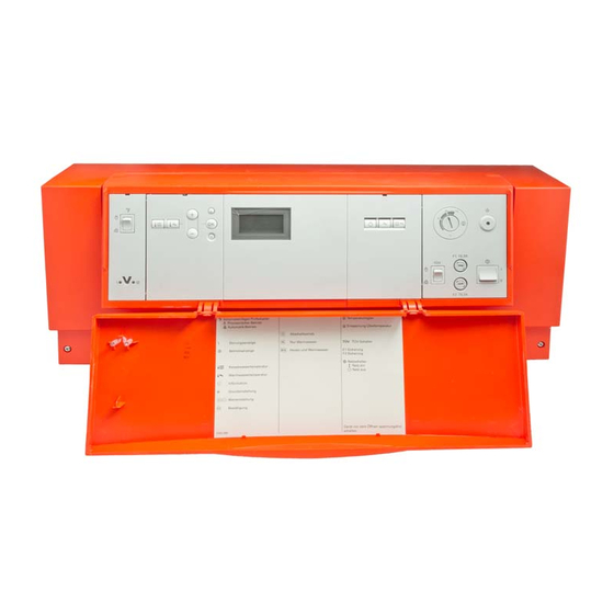
Installation sequence Opening the control unit... - Page 21 Commissioning Display and operating controls A User interface 1: C ON/OFF switch Set boiler water tempera- D Fuse F1 ture E Excess temperature reset Set DHW temperature F Control thermostat a/b Setting values G TEST key Confirmation (only for service purposes) Information H Emissions test switch Standard settings (reset)
-
Page 22: Testing The High Limit Safety Cut-Out
Commissioning Testing the high limit safety cut-out 1. Hold down the TEST key (position 3. Wait until the boiler water tempera- ), until the burner has shut down: ture has dropped approx. 15 to Pressing the TEST key bypasses 20 K below the selected safety thermostat . - Page 23 Commissioning Checking outputs (actuators) and sensors (cont.) Checking sensors 1. Press c. 3. Press d. Scanning operating conditions is Scanning is completed. enabled (see page 25). 2. Scan actual temperatures with b/...
-
Page 24: Service Scans Service Level Summary
Service scans Service level summary Function Key combination Exit Page Brief scans Press K and G approx. Press d 2 s simultaneously Relay test Press K and d approx. Press d 2 s simultaneously Operating condition Press c Press d Acknowledging fault dis- Press d play... -
Page 25: Operating Conditions
Service scans Brief scans (cont.) Display screen (flashes) Set cylinder temperature (if a cylinder temperature sensor is installed) Boiler coding card (see page 12) Operating conditions Scanning operating conditions 2. Select the required scan with a/ 3. Press d. Scanning is completed. 1. - Page 26 Service scans Operating conditions (cont.) 3. Press e. 5. Press d. The selected value will be set to "0". 4. To reset further values, repeat steps 2 and 3.
- Page 27 Troubleshooting Checking and acknowledging faults Fault display design A Fault display C Fault code B Fault number D Fault symbol The red fault indicator flashes for A fault message code flashes in the every fault. programming unit display when a fault message is issued.
-
Page 28: Troubleshooting Checking And Acknowledging Faults
Troubleshooting Checking and acknowledging faults (cont.) Calling up acknowledged fault mes- 2. Select the acknowledged fault with sages b/ b. 1. Press d for approx. 3 s. The fault will then be displayed. Fault code System character- Cause Measures istics with DHW cylin- Boiler water tem- Check the boiler water... -
Page 29: Calling Up Fault Codes From The Fault Memory (Fault History)
Troubleshooting Checking and acknowledging faults (cont.) Fault code System character- Cause Measures istics Cylinder primary Cylinder tempera- Check cylinder tempera- pump ON: ture sensor lead ture sensor Set cylinder tem- broken (see page 50) perature = Set boil- er water temperature, priority control is cancelled Control mode... -
Page 30: Faults That Are Not Displayed At The Programming Unit
Troubleshooting Faults that are not displayed at the programming unit Boiler cold, burner does not start Set the emissions test switch to Pumps are not running Check the operating voltage: Main isolator, power supply cable, plug fÖ, ON/OFF switch, fuses F1 6.3 A (slow) and F2 4 A (slow) Fuse F1 or F2 faulty? Pull off all 230 V plugs. - Page 31 Troubleshooting Faults that are not displayed at the programming . . . (cont.) Boiler hot enough, but the heating circuit pump will not run Set the emissions test switch to Pump running No pump control: Check set values, operating program, setting of the remote control;...
-
Page 32: Function Description Boiler Water Temperature Control
Function description Boiler water temperature control Brief description The boiler water temperature is The boiler water temperature is lim- regulated by starting up and shut- ited by the control thermostat. ting down the burner. Coding addresses that influence In the delivered condition, the the regulation of the boiler water switching differential is ±2 K, rela- temperature:... -
Page 33: Heating Circuit Control
Function description Boiler water temperature control (cont.) Control sequence The boiler goes cold: The boiler heats up: Set value -2 K Set value +2 K The burner start signal is set for a The burner shuts down. set boiler water temperature of -2 K, and the burner starts its own moni- toring program. -
Page 34: Cylinder Temperature Control
Function description Heating circuit control (cont.) DHW heating with priority control: OFF by the Vitotrol 100, type UTD; The heating circuit pump is the heating circuit pump runs con- switched OFF. stantly (code 01:0). DHW heating without priority con- The burner and heating circuit trol: pump will be switched ON or OFF The heating circuit pump remains... - Page 35 Function description Cylinder temperature control (cont.) Auxiliary function for DHW heating: DHW priority control This function is enabled by provid- With priority control (code "A2:2"): ing a second set DHW temperature The set flow temperature will be via coding address 58 and by adjusted to 0 °C whilst the cylinder enabling DHW heating via coding is being heated up.
- Page 36 Function description Cylinder temperature control (cont.) Adaptive cylinder heating active: Coding address 55:1 With adaptive cylinder heating, the speed of the temperature rise during DHW heating is taken into account. Also taken into account is the ques- tion of whether the boiler will be required to supply heat after the cylinder has been heated up or whether residual boiler heat should...
-
Page 37: Calling Up Coding Levels
Coding Calling up coding levels 1. Press L and G simultaneously 3. Confirm with d. for approx. 2 s. The value flashes. Access to the coding levels. 4. Change the value with a/b. 5. Confirm with d. After approx. 2 s, the address will flash again. - Page 38 Coding Coding summary (cont.) Coding in the delivered condition Possible change Boiler/burner 01:0 Burner control via the 01:1 Burner and heating cir- Vitotrol 100, type UTD cuit pump control via the room thermostat Vitotrol 100, type UTD (plug a-D); heating cir- room thermostat cuit pump runs con- (plug a-D);...
- Page 39 Coding Coding summary (cont.) Coding in the delivered condition Possible change 12:20 Shutdown delay for 12:0 Shutdown delay adjusta- blocking stage 1 (in ad- ble from 0 to 25472 Ks, dition to stage 2), (inte- 12:199 1 step 128 Ks gral) = 2560 Ks 13:6 Do not adjust...
- Page 40 Coding Coding summary (cont.) Coding in the delivered condition Possible change 60:20 During DHW heating, 60:10 The difference between the boiler water tem- the boiler water tempera- perature is up to 20 K 60:50 ture and the set DHW higher than the set temperature is adjustable DHW temperature from 10 to 50 K...
-
Page 41: Burner Switching Hysteresis
Coding Coding summary (cont.) Coding in the delivered condition Possible change F7:25 In program "Standby F7:0 Heating circuit pump OFF mode": Heating circuit F7:1 The heating circuit pump pump runs constantly is started for 10 min be- F7:24 tween 1 to 24 x daily Burner switching hysteresis Switching hysteresis 4 K (coding address 04:0) Heat demand-dependent switching hysteresis... - Page 42 Coding Burner switching hysteresis (cont.) The heat demand-dependent switch- The switching hysteresis, i.e the burn- ing hysteresis, therefore, takes the er runtime varies subject to actual boiler load into account. heat demand.
- Page 43 Designs Connection and wiring diagram Main PCB Programming unit Power supply unit PCB Boiler coding card Electronics PCB...
-
Page 44: Designs Connection And Wiring Diagram
Designs Connection and wiring diagram (cont.) Optolink PCB/emissions test Plug 230 V switch sÖ Heating circuit pump (acces- X... Electrical interfaces sories) F1, F2 Fuse sA Cylinder primary pump (acces- High limit safety cut-out " " sories) 110 °C (100 °C) fÖ... -
Page 45: Boiler Coding Card
Components Room thermostat Vitotrol 100, type UTD Part no. 7179 059 The Vitotrol 100 regulates the burner between the set boiler water temperature and the lower control range limit (minimum temperature). By changing coding address 01 (see coding summary), the Vitotrol 100 can affect the burner and the pump. -
Page 46: Vitoair Draught Stabiliser
Components Vitoair draught stabiliser Part no. 7338 725 and 7339 703 A To the burner B To the control unit Colour coding to DIN IEC 60757 black GN/YE green/yellow Function check Enable burner from the control unit The rotary selector should turn towards Burner OFF The rotary selector should turn... -
Page 47: Components From The Parts List
Components Vitoair draught stabiliser (cont.) Emergency mode Press the rotary selector on the motor and turn clockwise to the limit beyond position Components from the parts list Main PCB The main PCB comprises: Socket for connecting the Relay for selecting pumps and burn- Vitotrol 100, type UTD room thermo- stat Sockets for sensor connection... -
Page 48: Programming Unit
Components Components from the parts list (cont.) Optolink laptop interface through fuel oil preheating or Emissions test switch for testing Vitoair draught stabiliser) flue gas with briefly raised boiler Starting all pumps water temperature Regulation of the boiler water tem- The following functions are trig- perature by the control thermostat gered in position... - Page 49 Components Components from the parts list (cont.) High limit safety cut-out Type STB 56.10525.570, made Intrinsically safe; also lockout in by EGO, DIN STB 10602000 case of capillary tube leaks or ambi- ent temperatures below - 10 ºC Type 971.112X6.01A, made Limits the boiler water temperature by T&G, DIN STB 98103 to the maximum permissible value...
- Page 50 Components Components from the parts list (cont.) Burner connecting cables For boilers with pressure-jet oil/gas burners (for connection, see page 15). Boiler water temperature sensor and cylinder temperature sensor Note 1. Pull plug § or %. Connection see page 13 2.
- Page 51 Components Components from the parts list (cont.) Plug X12 Connection of external burner start (stage 1), see page 15.
-
Page 52: Parts Lists
Parts lists Parts lists When ordering spare parts 043 Cylinder temperature sensor with Quote the part and serial no. (see plug % type plate A) and the item no. of the 050 Electronics PCB required part (as per this parts list). 051 Optolink PCB Obtain standard parts from your local 052 Main PCB... - Page 53 Parts lists Parts lists (cont.)
- Page 54 Parts lists Parts lists (cont.)
-
Page 55: Specification
Specification Specification Rated voltage: 230 V Rated relay output breaking capacity Rated frequency: 50 Hz at 230 V : Rated current: Heating circuit Power consump- pump sÖ: 4 (2) A tion: Cylinder pri- Safety class: mary pump sA: 4 (2) A Protection: IP 20 D Burner plug fA:... -
Page 56: Settings And Equipment
Settings and equipment Settings and equipment Tick the adjusted function. Function in the delivered condi- Modified function tion High limit safety cut-out set to = Changed to ...ºC 110 ºC Control thermostat set to 75 ºC = Changed to ...ºC Electronic maximum limit = Changed to ...ºC Heating circuit pump... - Page 57 Settings and equipment Settings and equipment (cont.) Function in the delivered condi- Modified function tion = Room thermostat Vitotrol 100, type UTD affects the burner and the heating circuit pump = Two-stage burner extension = Vitoair...
-
Page 58: Keyword Index
Keyword index Keyword index Acknowledging a fault display Fault display ........Adaptive cylinder heating Fault display design . - Page 59 Keyword index Keyword index (cont.) Relay test TEST key ........
- Page 60 Applicability Product information/applicability Vitotronic 100, type KC2 Only for integration/installation in/on Viessmann boilers. Valid for control units: Part no. 7187 082 Viessmann Werke GmbH&Co KG Viessmann Limited D-35107 Allendorf Hortonwood 30, Telford Telephone: +49 6452 70-0 Shropshire, TF1 7YP, GB...
Need help?
Do you have a question about the VITOTRONIC 100 and is the answer not in the manual?
Questions and answers