Table of Contents
Advertisement
Advertisement
Table of Contents
Troubleshooting

Related Manuals for Matrix Fitness Johnny G KRANKcycle


Summary of Contents for Matrix Fitness Johnny G KRANKcycle
- Page 1 S E R V I C E M A N U A l...
-
Page 3: Table Of Contents
TAblE of CoNTENTS CHAPTER 1: SERIAl NUMbER loCATIoN .............. CHAPTER 2: IMPoRTANT SAfETy INSTRUCTIoNS Read and Save These Instructions ................2 CHAPTER 3: PREVENTATIVE MAINTENANCE Preventative Maintenance ..................3 CHAPTER 4: USINg THE KRANKcycle™ Getting to Know the KRANKcycle™ ................. 5 Proper Setup ...................... -
Page 4: Chapter 1: Serial Number Location
CHAPTER 1: SERIAl NUMbER loCATIoN 1.1 SERIAl NUMbER loCATIoN... -
Page 5: Chapter 2: Important Safety Instructions
CHAPTER 2: IMPoRTANT SAfETy INSTRUCTIoNS 2.1 READ AND SAVE THESE INSTRUCTIoNS It is the sole responsibility of the purchaser of Matrix Fitness * Keep your grip light while cranking and keep your elbows in Systems products to instruct all individuals, whether they are a neutral position. -
Page 6: Chapter 3: Preventative Maintenance
CHAPTER 3: PREVENTATIVE MAINTENANCE 3.1 PREVENTATIVE MAINTENANCE MoNTHly MAINTENANCE !WARNINg! Regular maintenance must be performed on the 1) For optimal performance of the resistance system, the following KRANKcycle™ for optimal performance and longevity. Please steps should be taken: read and follow all instructions below. If the cycle is not a. - Page 7 CHAPTER 3: PREVENTATIVE MAINTENANCE 3.1 PREVENTATIVE MAINTENANCE - CoNTINUED bI-yEARly (6 MoNTH) MAINTENANCE ITEMS 1) For optimal performance of the drive system, the following steps should be taken: a. Remove the Right crank arm by removing 5 socket head cap screws with a 4mm Allen wrench, then remove the upper outside plastic cover by removing 5 socket head cap screws with a 3mm Allen wrench.
-
Page 8: Chapter 4: Using The Krankcycle
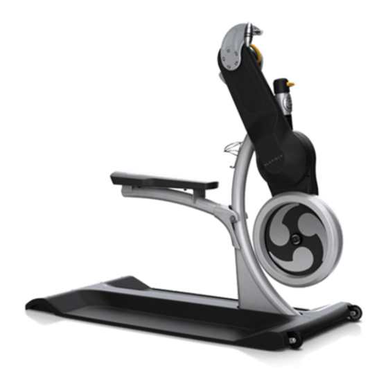
CHAPTER 4: USINg THE KRANKcycle™ 4.1 gETTINg To KNoW THE KRANKcycle™... -
Page 9: Proper Setup
CHAPTER 4: USINg THE KRANKcycle™ 4.2 PRoPER SET UP The KRANKcycle™ was designed explicitly for upper body and cardiovascular training. To maximize exercise effectiveness and comfort, the KRANKcycle™ should be adjusted for each user and exercise position. The instruction below describes one approach to adjusting the cycle to ensure optimal user comfort and ideal body positioning: you may choose to adjust the cycle differently. - Page 10 CHAPTER 4: USINg THE KRANKcycle™ 4.2 PRoPER SET UP - CoNTINUED To Krank while standing, first remove the seat and set aside. Stand with your With your back straight, position yourself on the saddle so that there is a slight back straight and your feet shoulder width apart.
-
Page 11: How To Operate
CHAPTER 4: USINg THE KRANKcycle™ 4.3 HoW To oPERATE RESISTANCE ADJUSTMENT The preferred level of difficulty in Kranking (resistance) can be regulated in fine increments by use of the resistance knob. To increase the resistance, turn the resistance knob toward the "+" sign; to decrease the resistance, turn the knob toward the "-" sign. IMPoRTANT: To stop the flywheel (wheel) while Kranking, turn the resistance knob toward the "+"... -
Page 12: Chapter 5: Troubleshooting
CHAPTER 5: TRoUblESHooTINg 5.1 TRoUblESHooTINg - CRANK ARMS NoT SyNCHRoNIzED CRANK ARMS NoT SyNCHRoNIzED Turn the resistance knob toward the "+" sign until the crank arms do not fall by themselves back to the lowest rest position. Raise the crank arms so the crank handles are level. -
Page 13: Troubleshooting - Excessive Play In Drive Arms
CHAPTER 5: TRoUblESHooTINg 5.2 TRoUblESHooTINg - EXCESSIVE PlAy IN DRIVE ARMS EXCESSIVE SIDE To SIDE PlAy IN DRIVE ARMS oR RoTATIoN lEVER PoPS UP WHIlE IN USE 1) Check if the rotational lever is fully engaged (A). If so, follow the next steps. 2) Remove the rotation lever and cap by removing 2 socket head cap screws with a 4mm Allen wrench. -
Page 14: Troubleshooting - Excessive Play In Height Adjustment Lever
CHAPTER 5: TRoUblESHooTINg 5.3 TRoUblESHooTINg - EXCESSIVE PlAy IN HEIgHT ADJUSTMENT lEVER EXCESSIVE PlAy IN PIVoTINg HEIgHT ADJUSTMENT lEVER 1) It is normal for the lever to exhibit a small amount of play before the upper drive arm is disengaged, but if the lever has excessive play (E), if when the lever is pulled to its full extent there is a pronounced clicking noise when the upper arm is rotated, or if when the lever is pulled no rotation is possible, follow the next steps. - Page 15 CHAPTER 5: TRoUblESHooTINg 5.3 TRoUblESHooTINg - EXCESSIVE PlAy IN HEIgHT ADJUSTMENT lEVER - CoNTINUED 5) If the cable / sheath do not have excessive wear, and tightening the adjustment screw does not resolve the problems, the issue may be with the connection of the cable to the pivot handle.
- Page 16 CHAPTER 5: TRoUblESHooTINg 5.3 TRoUblESHooTINg - EXCESSIVE PlAy IN HEIgHT ADJUSTMENT lEVER - CoNTINUED 7) Check the connection of the pivot handle cable to the pivot handle fulcrum (Figure E). The cable should be tight. Re-attach or tighten as needed. 8) Once the pivot handle cable is correctly attached, re-install the pivot handle (Figure F) and test the rotation before installing the shrouds to make sure that the tension on the pivot handle is correct.
-
Page 17: Troubleshooting - Flywheel Resistance Too Hard
CHAPTER 5: TRoUblESHooTINg 5.4 TRoUblESHooTINg - flyWHEEl RESISTANCE IS Too HARD flyWHEEl RESISTANCE IS Too HARD oR THE KNob REqUIRES Too MANy TURNS bEfoRE bECoMINg HARD 1) To adjust the brake pad setting, first remove the lower inside plastic cover by removing 6 socket head cap screws with a 3mm Allen wrench. 2) Loosen (do not remove) the brake cable screw (C), and turn the resistance knob toward the "-"... -
Page 18: Troubleshooting - Upper Drive Chain Making Clicking Noise
CHAPTER 5: TRoUblESHooTINg 5.5 TRoUblESHooTINg - UPPER CHAIN DRIVE MAKINg ClICKINg NoISE UPPER DRIVE CHAIN MAKINg A PRoNoUNCED ClICKINg NoISE 1) Over time, it is normal for the drive chains to stretch with use. The KRANKcycle™ is equipped with automatic chain tensioning devices, but the chain may need to be replaced if it has stretched too far. -
Page 19: Troubleshooting - Lower Drive Chain Making Clicking Noise
CHAPTER 5: TRoUblESHooTINg 5.6 TRoUblESHooTINg - loWER CHAIN DRIVE MAKES ClICKINg NoISE loWER DRIVE CHAIN MAKINg A PRoNoUNCED ClICKINg NoISE 1) Over time, it is normal for the drive chains to stretch. The KRANKcycle™ is equipped with automatic chain tensioning devices, but the chain may need to be replaced if it has stretched too far. -
Page 20: Troubleshooting - Cycle Difficult To Push When Moving
CHAPTER 5: TRoUblESHooTINg 5.7 TRoUblESHooTINg - CyClE DIffICUlT To PUSH WHEN MoVINg CyClE DIffICUlT To PUSH WHEN MoVINg 1) The front rolling wheels may need lubrication. Remove both wheels by unscrewing the nut and bolt. Lubricate the outside of the steel axle tube (A). -
Page 21: Troubleshooting - Resistance Knob Does Not Rotate Smoothly
CHAPTER 5: TRoUblESHooTINg 5.8 TRoUblESHooTINg - RESISTANCE KNob DoES NoT RoTATE SMooTHly RESISTANCE KNob DoES NoT RoTATE SMooTHly 1) The resistance cable mechanism may need lubrication. Remove the resistance knob by removing the 1 socket head cap screw with a 4mm Allen wrench. -
Page 22: Chapter 6: Part Replacement Guide
CHAPTER 6: PART REPlACEMENT gUIDE 6.1 CRANK ARM REPlACEMENT 1) Remove the 5 screws holding the crank to the frame (Figure A). 2) Remove the crank arm (Figure B). 3) Reverse Steps 1-2 to install a new crank arm. NOTE: Be sure that the spacer ring is reinstalled on the left side crank (Figure C). NOTE: Follow the procedure outlined in Section 5.1 if the arms are not synchronized. -
Page 23: Upper Plastic Shroud Replacement
CHAPTER 6: PART REPlACEMENT gUIDE 6.2 UPPER PlASTIC SHRoUD REPlACEMENT 1) Remove the right side crank as outlined in Section 6.1. 2) Remove the 5 screws attaching the upper plastic shroud to the frame (Figure A). 3) Remove the upper plastic shroud (Figure B). 4) Reverse Steps 1-3 to install a new upper plastic shroud. -
Page 24: Lower Plastic Shroud Replacement
CHAPTER 6: PART REPlACEMENT gUIDE 6.3 loWER PlASTIC SHRoUDS REPlACEMENT 1) Remove the right side crank as outlined in Section 6.1. 2) Remove the upper plastic shroud as outlined in Section 6.2. 3) Use a 3mm Allen wrench to remove the 6 screws holding the shrouds together (Figure A). 4) Use a 5 mm Allen wrench to remove the 3 screws holding the shrouds to the frame (Figure B). -
Page 25: Left Side Chain / Pulley Replacement
CHAPTER 6: PART REPlACEMENT gUIDE 6.4 lEfT SIDE CHAIN / PUllEy REPlACEMENT 1) Remove the right side crank as outlined in Section 6.1. 2) Remove the upper plastic shroud as outlined in Section 6.2. 3) Remove the lower plastic shrouds as outlined in Section 6.3. 4) Press the height adjustment lever and rotate the drive assembly towards the seat until the hole in the drive shaft aligns with the hole in the front of the frame (Figure A). -
Page 26: Right Side Chain / Pulley Replacement
CHAPTER 6: PART REPlACEMENT gUIDE 6.5 RIgHT SIDE CHAIN / PUllEy REPlACEMENT 1) Remove the right side crank as outlined in Section 6.1. 2) Remove the upper plastic shroud as outlined in Section 6.2. 3) Remove the lower plastic shrouds as outlined in Section 6.3. 4) Locate the hole in the frame around the small drive pulley on the right side of the KRANKcycle™... -
Page 27: Brake Pad Replacement
CHAPTER 6: PART REPlACEMENT gUIDE 6.6 bRAKE PAD REPlACEMENT 1) Remove the screw and nut holding the brake pad assembly to the frame (Figure A). 2) Remove the brake assembly (Figure B). NOTE: Be careful not to lose the rubber washers installed on the brake frame (Figure C). 3) Reverse Steps 1-2 to install a new brake pad assembly. -
Page 28: Height Adjustment Lever Replacement
CHAPTER 6: PART REPlACEMENT gUIDE 6.7 HEIgHT ADJUSTMENT lEVER REPlACEMENT 1) Remove the left side crank arm as outlined in Section 6.1. 2) Remove the 2 screws going up through the height adjustment lever into the frame (Figure A). 3) Swivel the height adjustment lever to the left and off of the unit (Figure B). 4) Reverse Steps 1-3 to install a new height adjustment lever. -
Page 29: Resistance Knob Replacement
CHAPTER 6: PART REPlACEMENT gUIDE 6.8 RESISTANCE KNob REPlACEMENT 1) Remove the screw holding the resistance knob to the frame (Figure A). 2) Remove the resistance knob (Figure B). 3) Reverse Steps 1-2 to install a resistance knob. fIgURE A fIgURE b... -
Page 30: Rotational Handle Replacement
CHAPTER 6: PART REPlACEMENT gUIDE 6.9 RoTATIoNAl HANDlE REPlACEMENT 1) Remove the screw holding the rotational handle in place (Figure A). 2) Remove the rotational handle (Figure B). 3) Reverse Steps 1-2 to install a new rotational handle. fIgURE A fIgURE b... -
Page 31: Rotational Cap Replacement
CHAPTER 6: PART REPlACEMENT gUIDE 6.10 RoTATIoNAl CAP REPlACEMENT 1) Remove the rotational handle as outlined in Section 6.9. 2) Remove the screw going through the top of the rotational cap (Figure A). 3) Remove the rotational cap (Figure B). 4) Reverse Steps 1-3 to install a new rotational cap. -
Page 32: Transport Wheel Replacement
CHAPTER 6: PART REPlACEMENT gUIDE 6.11 TRANSPoRT WHEEl REPlACEMENT 1) Remove the screw / nut holding the transport wheel to the frame (Figure A). 2) Remove the transport wheel (Figure B). 3) Reverse Steps 1-2 to install a new transport wheel. fIgURE A fIgURE b... -
Page 33: Crank Handle Replacement
CHAPTER 6: PART REPlACEMENT gUIDE 6.12 CRANK HANDlES REPlACEMENT 1) Use a 15mm wrench to turn the crank handle off of the crank arm (Figure A). NOTE: The left hand crank handle is reversed threaded (Turns clockwise to remove). 2) Remove the crank handle (Figure B). 3) Reverse Steps 1-2 to install new crank handles. -
Page 34: Chapter 7: Cycle Specifications And Assembly Guide
7.1 KRANKcycle™ SPECIfICATIoNS The Johnny G KRANKcycle™ by Matrix is designed according to EN957-5 standards as a Class S subcategory C product for professional and / or commercial use. Such training equipment is intended for use in training areas of commercial facilities such as Fitness Clubs or Sport Associations, where access and control is regulated by the person who has legal responsibility. -
Page 35: Fasteners And Assembly Tools
CHAPTER 7: CyClE SPECIfICATIoNS AND ASSEMbly gUIDE 7.2 fASTENERS AND ASSEMbly ToolS qUANTITy PART # SKETCH DESCRIPTION NOTES Flat Washer;M10 Black Socket Head Cap Screw;M10 x 25 Black Phillips Head Screw; M4 x 8 Socket Head Cap Screw;M5 x 20 8mm Allen Wrench 4mm Allen Wrench Phillips Head Screwdriver... -
Page 36: Assembly Instructions
CHAPTER 7: CyClE SPECIfICATIoNS AND ASSEMbly gUIDE 7.3 ASSEMbly INSTRUCTIoNS ATTENTIoN: Prior to assembling the KRANKcycle™, unpack all of the contents of the box and make sure that all necessary components are present. Review the contents of the hardware package for completeness. Contact your local distributor or contact Matrix customer service to report any missing items. -
Page 37: Leveling The Krankcycle
CHAPTER 7: CyClE SPECIfICATIoNS AND ASSEMbly gUIDE 7.3 ASSEMbly INSTRUCTIoNS - CoNTINUED Attach the DRIVE FRAME to the BASE FRAME using an 8mm ALLEN WRENCH and item 1-FLAT WASHER and item 2-SOCKET HEAD CAP SCREW. - Page 38 CHAPTER 7: CyClE SPECIfICATIoNS AND ASSEMbly gUIDE 7.3 ASSEMbly INSTRUCTIoNS - CoNTINUED Place the SMALL BASE PLATE FRONT COVER and the LARGE MAIN BASE PLATE on the metal frame.
- Page 39 CHAPTER 7: CyClE SPECIfICATIoNS AND ASSEMbly gUIDE 7.3 ASSEMbly INSTRUCTIoNS - CoNTINUED Secure the BASE PLATE to the BASE FRAME from step 3 with item 3-PHILLIPS HEAD SCREW and PHILLIPS HEAD SCREW DRIVER.
- Page 40 CHAPTER 7: CyClE SPECIfICATIoNS AND ASSEMbly gUIDE 7.3 ASSEMbly INSTRUCTIoNS - CoNTINUED Attach the LEFT HANDLE to the LEFT CRANK ARM and the RIGHT HANDLE to the RIGHT CRANK ARM. Please note that the LEFT HANDLE has a left hand thread.
- Page 41 CHAPTER 7: CyClE SPECIfICATIoNS AND ASSEMbly gUIDE 7.3 ASSEMbly INSTRUCTIoNS - CoNTINUED Secure the HANDLES tightly to the CRANK ARMS using a 15mm WRENCH.
- Page 42 CHAPTER 7: CyClE SPECIfICATIoNS AND ASSEMbly gUIDE 7.3 ASSEMbly INSTRUCTIoNS - CoNTINUED Attach the WATER BOTTLE CAGE to the CENTER UPRIGHT FRAME with a 4mm ALLEN WRENCH using item 4-SOCKET HEAD CAP SCREWS.
- Page 43 CHAPTER 7: CyClE SPECIfICATIoNS AND ASSEMbly gUIDE 7.3 ASSEMbly INSTRUCTIoNS - CoNTINUED Attach the SEAT to the UPRIGHT FRAME by securely placing the SEAT HOOKS around the PROTRUDING PINS. !WARNINg! Make sure that the seat hooks are fully engaged around the protruding center pin.
- Page 44 CHAPTER 7: CyClE SPECIfICATIoNS AND ASSEMbly gUIDE 7.4 lEVElINg THE KRANKcycle™ STABILIZING THE KRANKcycle™ After positioning the KRANKcycle™ in its intended location, check its stability by attempting to shake it side to side. Shaking or rocking indicates that your cycle needs to be leveled. Determine which leveler is not resting completely on the floor. Turn the leveler until the rocking motion is eliminated.
- Page 45 NoTES...
- Page 46 MATRIX fITN E S S S yS TE MS C oR P. 1610 LANDM ARK D RIv E C OTTA GE G R Ov E W I 5 352 7 U S A w w w. m a t r i x f i t n e s s . c o m TOLL FREE 866.693.4863 FA X 60 8.
Need help?
Do you have a question about the Johnny G KRANKcycle and is the answer not in the manual?
Questions and answers