Table of Contents
Advertisement
Quick Links
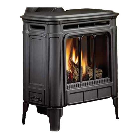
H27 Direct Vent Gas Fireplace
MODELS:
H27-NG10 Natural Gas
WARNING
FIRE OR EXPLOSION HAZARD
Failure to follow safety warnings exactly could result in serious
injury, death, or property damage.
- Do not store or use gasoline or other flammable vapors and liquids in the vicinity of this or any other
appliance.
- WHAT TO DO IF YOU SMELL GAS
• Do not try to light any appliance.
• Do not touch any electrical switch: do not use any phone in your building.
Leave the building immediately.
• Immediately call your gas supplier from a neighbour's phone. Follow the gas supplier's
instructions.
• If you cannot reach your gas supplier, call the fire department.
Installation and service must be performed by a qualified installer, service agency or the gas supplier.
Tested by:
919-484a
FPI FIREPLACE PRODUCTS INTERNATIONAL LTD. 6988 Venture St., Delta, BC Canada, V4G 1H4
H27-LP10 Propane
Installer: Please complete the details on the back cover
and leave this manual with the homeowner.
Homeowner: Please keep these instructions for future reference.
Owners &
Installation Manual
www.hampton-fire.com
09.01.15
Advertisement
Table of Contents

Related Manuals for HAMPTON BAY H27-NG10


Summary of Contents for HAMPTON BAY H27-NG10
- Page 1 Owners & H27 Direct Vent Gas Fireplace Installation Manual www.hampton-fire.com MODELS: H27-NG10 Natural Gas H27-LP10 Propane WARNING FIRE OR EXPLOSION HAZARD Failure to follow safety warnings exactly could result in serious injury, death, or property damage. - Do not store or use gasoline or other flammable vapors and liquids in the vicinity of this or any other appliance.
- Page 2 HAMPTON ® Direct Vent Freestanding Gas Stove To the New Owner: Congratulations! You are the owner of a state-of-the-art Hampton Gas Stove by REGENCY FIREPLACE PRODUCTS. The H27-10 is a ® hand crafted appliance and has been designed to provide you with all the warmth and charm of a wood fireplace at the flick of a switch.
-
Page 3: Table Of Contents
table of contents Copy Of Safety Label ............4 Converting Class-A Metal Chimney Or .......29 Unit Dimensions With Vertical Venting ......6 Masonry Chimney To Direct Vent System ....29 Unit Dimensions With Horizontal Venting ......7 Cathedral Ceilings ............30 Important Message Save These Instructions ....8 High Elevation .............30 Specifications ..............8 Gas Connection ............30... -
Page 4: Copy Of Safety Label
Serial No./ No de serie Conforms to: ANSI Z21.88-2014 Certified to: CSA 2.33-2014 4001172 MAY BE INSTALLED IN MANUFACTURED (MOBILE) HOMES AFTER FIRST SALE. Model:H27-NG10 FACTORY EQUIPPED FOR NATURAL GAS É QUIP É A L'UISINE POUR GAZ NATURAL Minimum supply pressure 5"... -
Page 5: For The State Of Massachusetts Only
requirements MA Code - CO Detector (for the State of Massachusetts only) 5.08: Modifications to NFPA-54, Chapter 10 (2) Revise 10.8.3 by adding the following additional requirements: (a) For all side wall horizontally vented gas fueled equipment installed in every dwelling, building or structure used in whole or in part for residential purposes, including those owned or operated by the Commonwealth and where the side wall exhaust vent termination is less than seven (7) feet above finished grade in the area of the venting, including but not limited to decks and porches, the following requirements shall be satisfied:... -
Page 6: Unit Dimensions With Vertical Venting
dimensions UNIT DIMENSIONS WITH VERTICAL VENTING 17 13/16” (452 mm) Hampton H27-10 Direct Vent Freestanding Gas Stove ®... -
Page 7: Unit Dimensions With Horizontal Venting
installation UNIT DIMENSIONS WITH HORIZONTAL VENTING (452 mm) Hampton H27-10 Direct Vent Freestanding Gas Stove ®... -
Page 8: Important Message Save These Instructions
Simpson Dura-Vent instructions. copper wire from the steel chassis ground must be attached. SPECIFICATIONS Fuels: H27-NG10 is approved for use with This appliance may only be installed in an natural gas. aftermarket permanently located, manufac- YOUNG CHILDREN SHOULD BE CARE-... -
Page 9: General Safety Information
installation INSTALLATION 1) Provide adequate clearances for servicing, GENERAL SAFETY proper operation and around the air openings CHECKLIST INFORMATION into the combustion chamber. 1) Locate your appliance. Refer to the following 2) The appliance must be installed on a flat, solid, 1) The appliance installation must conform with sections: continuous surface (e.g. -
Page 10: Clearances To Combustibles
Use the minimum clearances shown in the dia- Flat on Wall Corner grams below: Flush with Wall/Alcove For Vent Termination requirements, see "Exterior H27-NG10 & H27-LP10 Clearances Vent Terminal Locations" section. A Left Side Wall to Unit* 6" / 150 mm B Back Wall to Unit 3"... -
Page 11: Optional Fan Installation
installation H27-10 OPTIONAL FAN INSTALLATION OPTIONAL FAN INSTALLATION 6. Secure the fan assembly wire with a strain relief on the back NOTE: It is recommended to connect wires first – then install the of the left side access panel. fan assembly to allow for more room when installing onto the unit. 1. -
Page 12: Glass Front Removal / Installation
installation GLASS FRONT OPTIONAL WALL THERMOSTAT REMOVAL / INSTALLATION INSTALLATION 1. Turn off stove and allow it to return to room temperature. NOTE: This appliance comes equipped with a standard remote control. This remote control controls both the flame height and fan speed. If 2. -
Page 13: Venting Introduction
1) Wear gloves and safety glasses for protection. in combination with the Direct Vent Freestanding the H27-NG10, and H27-LP.10 The warranty will Gas Stoves, H27-NG10, and H27-LP10, have been be voided and serious fire, health or other safety... -
Page 14: Exterior Vent Terminal Locations
installation EXTERIOR VENT TERMINAL LOCATIONS Minimum Clearance Requirements Canada Clearance above grade, veranda, porch, deck, or balcony 12"(30cm) 12"(30cm) Clearance to window or door that may be opened 12"(30cm) 9" (23cm) Clearance to permanently closed window Vertical clearance to ventilated soffit located above the terminal within a horizontal distance of 2 feet (61cm) 22"(56cm) 22"(56cm) from the center line of the terminal (check with the local code) -
Page 15: 4" X 6-5/8" Rigid Pipe Cross Reference Chart
installation 4” X 6-5/8” RIGID PIPE CROSS REFERENCE CHART Components from different Manufacturers may not be mixed. Not All Rigid Pipe components are available directly from FPI. 4” X 6- 5/8” RIGID PIPE CROSS REFERENCE CHART Components from different Manufacturers may not be mixed. Not all rigid pipe components are available directly from Regency. Note: The listed manufacturers may have other lengths not shown on this chart, which would also be approved. - Page 16 installation Description Selkirk American Metal Security ICC Excel Simpson Metal-Fab™ Direct Temp™ Secure- Vent® Direct Direct Vent Pro ® Products® Sure Seal Amerivent Direct Attic Insulation Shield 12” 46DVA-IS 4DAIS12 SV4RSA N/A@ FPI Attic Insulation Shield - 36” 4DAIS12 TM-4AS Cold Climates Basic Horizontal Termination Kit (A) Disc.
-
Page 17: Rigid Pipe Venting Systems
installation RIGID PIPE VENTING SYSTEMS Horizontal or Vertical Terminations Vertical Alternate Termination Horizontal Termination Caps Storm Collar Vinyl Siding Standoff (Optional) Flashing Horizontal Termination Ceiling Firestop Wall Thimble Pipe Length Adj.Pipe Length 90 Elbow WARNING: Pipe Do not combine venting components from Length different venting systems. -
Page 18: Venting Arrangements
installation VENTING ARRANGEMENTS Vertical Terminations Systems for Horizontal Terminations for All Venting Systems Residential Manufactured and Mobile Homes The shaded areas in the diagram below show all The shaded area in the diagram below shows all allowable combinations of straight allowable combinations of vertical runs with hori- vertical and offset to vertical runs with vertical terminations. - Page 19 installation Horizontal Venting with Two (2) 90 Elbows One 90 elbow = Two 45 elbows. Option H + H1 With these options, maxi- mum total pipe length is 30 2' Min. 4' Max. feet with minimum of 6 feet 3' Min. 5' Max.
- Page 20 installation Vertical Venting with Two (2) 90 Elbows One 90 elbow = Two 45 elbows. Option V V + V1 With these options, max. total pipe length is 30 feet with min. 1' Min. 4' Max. 2' Min. of 6 feet total vertical and max. 2' Min.
-
Page 21: Vertical Termination With Co-Linear Flex System
installation VERTICAL TERMINATION WITH CO-LINEAR FLEX SYSTEM THE APPLIANCE MUST NOT BE Masonry chimneys may take various contours which the flexible liner will accommodate. However, CONNECTED TO A CHIMNEY FLUE keep the flexible liner as straight as possible, avoid unnecessary bending. SERVING A SEPARATE SOLID FUEL BURNING APPLIANCE. -
Page 22: Dv Stove Horizontal Vent Kit
installation DV STOVE HORIZONTAL VENT KIT DV 2 ft. Stove Vent Kit (Part # 946-116) and DV 4 ft. Stove Vent Kit (946-216) includes all the parts needed to install the H27 Direct Vent unit with minimum horizontal and vertical vent dimensions. For installations that require longer vertical and/or horizontal vents use the Dura-Vent system as shown in the "Dura-Vent Termination Kit"... - Page 23 installation with Mill-Pac and 3 of the #8 x 1/2" screws (stainless steel). 10) Slide the decorative Thimble Cover over the pipe sections and secure with 4 screws (#8 x 1-1/2" drill point, black) to the wall. 11) Slide the 90 elbow (crimp end up), the 45 elbow and the 4 ft.
-
Page 24: Residential And Manufactured Homes / Mobile Homes
installation RESIDENTIAL AND MANUFACTURED HOMES / MOBILE HOMES MINIMUM HORIZONTAL TERMINATION INSTALLATIONS Planning Your venting Installation You will require the following components with your new Hampton Rear Vent Direct Vent Free- ® See the "Exterior Vent Terminal Locations" standing Gas Stove. Please review your product to make sure you have everything you need. In section for requirements. -
Page 25: Dura-Vent Termination Kit
installation DURA-VENT TERMINATION KIT thimble is suitable for 2 x 4 or 2 x 6 wall construc- Be sure to check the vent termination clearance Planning Your Dura-Vent tion.) Select the amount of vertical rise desired requirements from decks, windows, soffits, gas Installation for "vertical-to-horizontal"... -
Page 26: Horizontal Terminations
installation You will require the following components with your new Direct Vent Freestanding Gas Stove. Please review your product to make sure you have everything you need. In the event that you are missing any part, contact your dealer. Note: These are the minimum pieces re- quired. -
Page 27: Vertical Terminations
installation c) Before connecting the vent pipe to the vent termination, slide the black decorative wall thimble cover over the vent pipe, then slide the Wall Penetration Heat Shield over the vent pipe. Dia. 3. d) Slide the appliance and vent assembly towards the wall carefully inserting the vent pipe into the riser vent terminal assembly. -
Page 28: Offset Chart
installation 7) Ensure vent is vertical and secure the base of the flashing to the roof with roofing rails, slide storm collar over the pipe section and seal with a mastic. 8) Install the vertical termination cap by twist locking it. Notes: a) For multistorey vertical installations, a Ceiling Fire stop is required at the... -
Page 29: Converting Class-A Metal Chimney Or
installation CONVERTING CLASS-A 4) Pass the flex pipe down through the center The use of an existing chimney as an air of the chimney system, and center the intake is not covered under the ANSI Z21.88- METAL CHIMNEY OR adaptor on the top of the chimney pipe. 2014, CSA 2.33-2014 test methods and the MASONRY CHIMNEY TO Drill four 1/8"... -
Page 30: Cathedral Ceilings
installation 8) Ensure vent is vertical and secure the base of Note: If you are using a 6" square support Since some municipalities have additional local the flashing to the roof with roofing rails, slide you may find it difficult to screw it in codes it is always best to consult with your local place because it is fairly small inside. -
Page 31: Aeration Adjustment
installation AERATION GAS PIPE 885 S.I.T. VALVE ADJUSTMENT PRESSURE TESTING DESCRIPTION 1) 6 Stage flame adjustment The burner aeration is factory set but may need The appliance must be isolated from the gas sup- 2) Pilot adjustment adjusting due to either the local gas supply, air sup- ply piping system by closing its individual manual 3) Inlet Pressure Tap ply or altitude. -
Page 32: Conversion Kit From Ng To Lp
installation CONVERSION KIT # 357-969 FROM NG TO LP CONVERSION KIT FROM NG TO LP THIS CONVERSION MUST BE DONE BY A QUALIFIED GAS FITTER IF IN DOUBT DO NOT DO THIS CONVERSION !! 11. Remove NG stepper motor by remov- ing 2 screws in locations shown below. Unscrew the pilot orifice with the allen key Replace with LP stepper motor, secure Each Kit contains one LPG and replace with the LP pilot orifice in the in place with 2 screws. -
Page 33: Log Set Installation
installation H25 / H27 LOG SET INSTALLATION LOG SET INSTALLATION Read the instructions below carefully and refer to the dia- grams. If the logs are broken do not use the unit until they are Place the rear log on the 2 rear log locating pins on the rear replaced. - Page 34 H25 / H27 installation Take the embers and place on the burner in the space be- Logs must be oriented as shown below. tween the 2 front logs. Do not put embers on the burner in the area between the front logs and the rear log. See photo below.
-
Page 35: Optional Wall Thermostat
installation MANUAL OPERATION REMOTE/RECEIVER CODING OPTIONAL WALL (NO REMOTE) To code the receiver to the handheld remote, followt To override the remote - open thefront access THERMOSTAT the procedure below: panel and the valve cover plate. Press the red button on IFC until it beeps 3 times and the 1. -
Page 36: Wiring Diagram Without Thermostat
installation WIRING DIAGRAM WITHOUT THERMOSTAT This heater does not require a 120V A.C. supply CAUTION: Ensure that the wires do WARNING: for operation. In case of a power failure, the re- not touch a hot surface and are away Electrical Grounding mote control/thermostat will continue to operate. -
Page 37: Wiring Diagram With Thermostat
operating instructions WIRING DIAGRAM WITH THERMOSTAT Thermostat (Optional) (Millivolt) Hampton H27-10 Direct Vent Freestanding Gas Stove ®... -
Page 38: First Fire
operating instructions FIRST FIRE 8. Remote control requires coding. See remote coding instructions for details. The first fire in your stove is part of the paint curing NOTE: This appliance will operate with 4 AA back-up process. To ensure that the paint is properly cured, batteries installed (see Back-up Battery section it is recommended that you burn your fireplace for details) during power outages. -
Page 39: Lighting Procedure
operating instructions LIGHTING PROCEDURE IMPORTANT: The remote control system supplied with this appliance has Note: The first try for ignition will last approximately 60 seconds. If there is no several options for starting/operating the appliance using the power button flame ignition (rectification) the board will stop sparking for approximately and ON/OFF key on the hand held transmitter. -
Page 40: Copy Of The Lighting Plate Instructions
operating instructions COPY OF THE LIGHTING PLATE INSTRUCTIONS FOR YOUR SAFETY READ BEFORE LIGHTING This appliance must be installed in accordance with local codes, if any; if none, follow the National Fuel Gas Code, ANSI Z223.1/NFPA 54, or Natural Gas and Propane Installation Codes, CSA B149.1. WARNING: If you do not follow these instructions exactly, a fire or explosion may result causing property damage, personal injury or loss of life. -
Page 41: Normal Operating Sounds Of Gas Appliances
maintenance NORMAL OPERATING 2) Clean glass (never when unit is hot), appliance, CAUTION: ANY SAFETY SCREEN and door with a damp cloth. Never use an SOUNDS OF OR GUARD REMOVED FOR SER- abrasive cleaner. GAS APPLIANCES VICING AN APPLIANCE MUST BE 3) The heater is finished in a porcelain finish or REPLACED PRIOR TO OPERATING with a heat resistant paint and should only be... -
Page 42: Glass Replacement
maintenance GLASS FAN MAINTENANCE GENERAL VENT REPLACEMENT MAINTENANCE If your fan requires maintenance or replacement, Your stove is supplied with high temperature, 5 access to the fan is through the rear access panel mm Neoceram ceramic glass that will withstand on the back of the unit. -
Page 43: Safety Screen Removal / Installation
maintenance VALVE ASSEMBLY SAFETY SCREEN REMOVAL / 12. Carefully lift the valve tray assembly up and REPLACEMENT out of the unit to remove. INSTALLATION 1. Turn off stove and allow ot return to room tem- 13. Replace with new valve assembly and reverse If your valve requires maintenance or replacement, purature. -
Page 44: Main Assembly
parts list MAIN ASSEMBLY Part # Description Part # Description Part # Description 357-201** Casting Top-Charcoal *Note: Not available as a replacement part. 350-022 Casting Mount Bracket 357-211** Front Cast -Charcoal Fan Air Divider 357-241** Right Side Cast- Charcoal W260260 Top Relief Frame Gasket **Last digit of part number indicates colour: 357-231**... -
Page 45: Burner & Log Assembly
parts list BURNER & LOG ASSEMBLY Part # Description 911-011 Stepper Motor -LP 911-085 Novasit Valve LP 885 SIT 910-100 Noavsit Pilot Orifice - NG 911-084 Novasit Valve -NG 885 910-101 Novasit Pilot Orifice -LP 904-430 #42 Orifice -NG 911-039 Novasit Pilot Hood 2 Way 904-163 #54 Orifice - LP... - Page 46 notes 46 | Hampton H27-10 Direct Vent Freestanding Gas Stove ®...
-
Page 47: Warranty
WARRANTY For Models: H15 H25 H35 warranty Hampton Fireplace Products are designed with reliability and simplicity in mind. In addition, our internal Quality Assurance Team carefully inspects each unit thoroughly before it leaves our facility. FPI Fireplace Products International Ltd. is pleased to extend this limited lifetim e warranty to the original purchaser of a Hampton Product. - Page 48 Register your Regency warranty online ® www.regency-fire.com Reasons to register your product online today! • View and modify a list of all your registered products. • Request automatic email notification of new product updates. • Stay informed about the current promotions, events, and special offers on related products.
Need help?
Do you have a question about the H27-NG10 and is the answer not in the manual?
Questions and answers