Table of Contents
Advertisement
Quick Links
15-400
Horizontal Metal Bandsaw
Operator's Manual
Record the serial number and date of purchase in your manual for future reference.
Serial Number: _________________________
Date of purchase: _________________________
For technical support or parts questions, email techsupport@rikontools.com or call toll free at (877)884-5167
www.rikontools.com
15-400M1
Advertisement
Table of Contents

Related Manuals for Rikon Power Tools 15-400


Summary of Contents for Rikon Power Tools 15-400
- Page 1 15-400 Horizontal Metal Bandsaw Operator’s Manual Record the serial number and date of purchase in your manual for future reference. Serial Number: _________________________ Date of purchase: _________________________ For technical support or parts questions, email techsupport@rikontools.com or call toll free at (877)884-5167 www.rikontools.com...
-
Page 2: Table Of Contents
TABLE OF CONTENTS Specifications........................2 Safety Instructions ......................3 - 6 Getting To Know Your Tile Saw ....................7 Contents of Package .....................8 Assembly ......................... 9 - 11 Adjustments ........................12 - 15 Operation....................15-17 Maintenance ........................18 Electricals & Wiring Diagram ..................5 & 18 Troubleshooting ......................19 Parts Diagram &... -
Page 3: Safety Instructions
SAFETY INSTRUCTIONS IMPORTANT! Safety is the single most important consideration in the operation of this equipment. The following instructions must be followed at all times. Failure to follow all instructions listed below may result in electric shock, fire, and/or serious personal injury. There are certain applications for which this tool was designed. - Page 4 SAFETY INSTRUCTIONS 12. KEEP PROTECTIVE GUARDS IN PLACE AND IN 25. ALWAYS WEAR A DUST MASK TO PREVENT WORKING ORDER. INHALING DANGEROUS DUST OR AIRBORNE PARTICLES, including wood dust, crystalline silica dust 13. AVOID ACCIDENTAL STARTING. Make sure that and asbestos dust. Direct particles away from face and the power switch is in the “OFF”...
-
Page 5: Electricals & Wiring Diagram
SAFETY INSTRUCTIONS ELECTRICAL SAFETY EXTENSION CORDS THIS TOOL IS PRE-WIRED FOR 120V THE USE OF AN EXTENSION CORD WITH THIS MACHINE IS NOT RECOMMENDED. For CIRCUITS, AND MUST BE GROUNDED WHILE IN USE TO PROTECT THE OPERATOR FROM ELECTRIC SHOCK. best power and safety, plug the machine directly into a dedicated, grounded electrical outlet that is within the IN THE EVENT OF A MALFUNCTION OR BREAKDOWN,... -
Page 6: Safety Instructions
SAFETY INSTRUCTIONS SPECIFIC SAFETY INSTRUCTIONS FOR METAL CUTTING SAWS This machine is intended for the cutting of metal material. The permissible workpiece dimensions must be observed (see Technical Specification). Any other use not as specified, including modification of the machine or use of parts not tested and approved by the equipment manufacturer, can cause unforeseen damage and invalidate the warranty. -
Page 7: Getting To Know Your Tile Saw
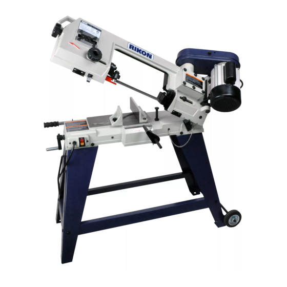
GETTING TO KNOW YOUR METAL CUTTING SAW Drive Belt Cover Motor Vise Lifting Handle Blade Tension Knob Stand Feed Speed Work Stop Handle Switch Vise Handle Mobility Wheels Mobility Handle... -
Page 8: Contents Of Package
CONTENTS OF PACKAGE Model 15-400 4” x 6” Horizontal Metal Cutting Bandsaw is shipped complete in one box. Unpacking, Checking Contents & Clean-up 1. Carefully remove all contents from the shipping carton. Compare the contents with the list of contents to make sure that all of the items are accounted for, before discarding any packing material. -
Page 9: Assembly
ASSEMBLY THE MACHINE MUST NOT BE PLUGGED IN AND THE POWER SWITCH MUST BE IN THE OFF POSITION UNTIL ASSEMBLY IS COMPLETE. STAND ASSEMBLY 1. With the help of an assistant, lift the band saw onto a suitable support. Example: Figure 1. Short Brace (x2) 2. - Page 10 ASSEMBLY THE MACHINE MUST NOT BE PLUGGED IN AND THE POWER SWITCH MUST BE IN THE OFF POSITION UNTIL ASSEMBLY IS COMPLETE. STAND ASSEMBLY Continued from page 9. 6. Slide the shaft through the holes in the wheel mounting bracket. Slide the wheels onto the shaft on the outside of the mounting bracket, and secure them with the cotter pins.
- Page 11 ASSEMBLY THE MACHINE MUST NOT BE Motor Pulley PLUGGED IN AND THE POWER SWITCH MUST BE IN THE OFF POSITION UNTIL ASSEMBLY IS COMPLETE. MOTOR & DRIVE PULLEY INSTALLATION Drive Pulley 1. Open the pulley cover and slide the motor pulley over the motor shaft.
-
Page 12: Adjustments
ADJUSTMENTS Fixed Jaw THE MACHINE MUST NOT BE PLUGGED IN AND THE POWER SWITCH MUST BE IN THE OFF POSITION UNTIL ASSEMBLY IS COMPLETE. VISE ADJUSTMENTS For Straight Cuts: 1. Loosen the two hex bolts on the fixed jaw (A-Fig. 11). 2. - Page 13 ADJUSTMENTS THE MACHINE MUST NOT BE PLUGGED IN AND THE POWER SWITCH MUST BE IN THE OFF POSITION UNTIL ASSEMBLY IS COMPLETE. Knob ADJUSTING THE BLADE GUIDES Blade Guides 1. Loosen the guide post knob and slide the blade guide as close to the workpiece as possible.
- Page 14 ADJUSTMENTS THE MACHINE MUST NOT BE PLUGGED IN AND THE POWER SWITCH MUST BE IN THE OFF POSITION UNTIL ASSEMBLY IS COMPLETE. CHANGING BLADE SPEED Continued from page 13. 1. Open the motor cover. SEE Figure 17. NOTE: The Speed Change Label shown in Motor Cover Figure 16, page 13, can be found inside the motor cover.
-
Page 15: Operation
ADJUSTMENTS THE MACHINE MUST NOT BE PLUGGED IN AND THE POWER SWITCH MUST BE IN THE OFF POSITION UNTIL ASSEMBLY IS COMPLETE. HEAD LOCK PIN The head locking pin safely secures the head (bow) in the down position. To ensure the head does not unexpectedly spring up and tip the band saw over, this locking pin must be properly in- serted when the band saw is not in use or before... - Page 16 OPERATION THE MACHINE MUST NOT BE PLUGGED IN AND THE POWER SWITCH MUST BE IN THE OFF POSITION UNTIL ASSEMBLY IS COMPLETE. Safety Bracket VERTICAL CUTTING 1. Raise the saw head and engage the safety bracket. Notch 2. Lock the safety bracket in place with the supplied pin (on front of saw) to keep the saw head from falling.
- Page 17 OPERATION THE MACHINE MUST NOT BE PLUGGED IN AND THE POWER SWITCH MUST BE IN THE OFF POSITION UNTIL ASSEMBLY IS COMPLETE. CHANGING THE SAW BLADE 1. Turn the on/off switch to the OFF position and disconnect saw from power source. Safety Bracket 2.
-
Page 18: Maintenance
MAINTENANCE BEFORE CLEANING OR CARRYING OUT MAINTENANCE WORK, DISCONNECT THE MACHINE FROM THE POWER SOURCE (WALL SOCKET). DO NOT USE COMPRESSED AIR NEAR BEARINGS. REGULAR MAINTENANCE OF THE MACHINE WILL PREVENT UNNECESSARY PROBLEMS. 1. Avoid using solvents when cleaning plastic parts. Most plastics are susceptible to damage from various types of commercial solvents and may be damaged by their use. -
Page 19: Troubleshooting
TROUBLESHOOTING SYMPTOM POSSIBLE CAUSES SOLUTIONS Saw will not start 1. Power cord is not plugged in 1. Plug in saw to power source 2. Fuse or circuit tripped 2. Replace fuse or reset breaker 3. Damaged power cord 3. Contact Technical Support 877-884-5167 4. -
Page 20: Parts Diagram & Parts Lists
PARTS DIAGRAM &167A... - Page 21 PARTS LIST DESCRIPTION KEY NO. PART NO. DESCRIPTION PART NO. KEY NO. Worm gear pulley P15-400-1 4-0.7x8mm Flat head screw P15-400-55 8-1.25x8mm Set screw P15-400-2 Bushing P15-400-56 P15-400-3 4-0.7x8mm Pan head screw P15-400-57 Front blade wheel P15-400-4 4mm Flat washer 8-1.25x8mm Set screw P15-400-58 4-0.7x8mm Flat head screw...
- Page 22 PARTS LIST DESCRIPTION PART NO. KEY NO. PART NO. KEY NO. DESCRIPTION Shaft Cord clamp P15-400-163 P15-400-109 629zz Ball bearing Pin with chain P15-400-164 P15-400-110 9mm Retaining ring P15-400-111 5mm Flat washer P15-400-165 Rear blade guard P15-400-112 5-0.8x20mm Pan head screw P15-400-166 4mm Flat washer P15-400-113...
-
Page 23: Warranty
® 5-Year Limited Warranty RIKON Power Tools Inc. (“Seller”) warrants to only the original retail consumer/purchaser of our products that each product be free from defects in materials and workmanship for a period of five (5) years from the date the product was purchased at retail. This warranty may not be transferred. - Page 24 15-400 For more information: 16 Progress Road Billerica, MA 01821 877-884-5167 / 978-528-5380 techsupport@rikontools.com www.rikontools.com 15-400M1...
Need help?
Do you have a question about the 15-400 and is the answer not in the manual?
Questions and answers