Table of Contents
Advertisement
Quick Links
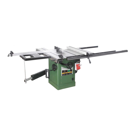
10" Cabinet Saw Sliding Table
Model: 10-110B/E
Record the serial number and date of purchase
in your manual for future reference.
Serial number:
Date of purchase:
For more information:
www.rikontools.com
info@rikontools.com
or
For Parts or Questions:
Part #10-110B/EM2
techsupport@rikontools.com
877-884-5167
or
Advertisement
Table of Contents

Related Manuals for Rikon Power Tools 10-110B


Summary of Contents for Rikon Power Tools 10-110B
- Page 1 10” Cabinet Saw Sliding Table Model: 10-110B/E Record the serial number and date of purchase in your manual for future reference. Serial number: Date of purchase: For more information: www.rikontools.com info@rikontools.com For Parts or Questions: Part #10-110B/EM2 techsupport@rikontools.com 877-884-5167...
-
Page 2: Safety Warnings
Operator Safety: Required Reading IMPORTANT! Safety is the single most important consideration in the operation of this equipment. The following in- structions must be followed at all times. There are certain applications for which this tool was designed. We strongly recommend that this tool not be modifi ed and/or used for any other application other than that for which it was designed. -
Page 3: Table Saw Safety Rules
ALWAYS DISCONNECT TOOLS. Disconnect tools before servicing and when changing accessories such as blades, bits, and cutters. ALWAYS AVOID ACCIDENTAL STARTING. Make sure switch is in “OFF” position before plugging in cord. NEVER LEAVE TOOLS RUNNING UNATTENDED. ALWAYS CHECK FOR DAMAGED PARTS. Before initial or continual use of the tool, a guard or other part that is damaged should be checked to assure that it will operate properly and perform its intended function. -
Page 4: Table Of Contents
Table of Contents Safety Warnings............................2 -3 Table Saw Safety Rules ..........................3 Specifi cations ............................4 Contents of Package ..........................5 Unpacking and Checking Contents ....................5-6 Getting To Know Your Sliding Table ......................7 Assembly ..............................8-12 Adjustment...........................12-13 Operation........................13-14 Rip Fence Installation............................15 Maintenance ............................... 15 Troubleshooting............................16 Parts Diagram...........................17 Parts List........................18... -
Page 5: Contents Of Package
Content of Package Model 10-110B/E 10” Table Saw Sliding Table is shipped complete in 2 boxes. Unpacking and Checking Contents Separate all “loose parts” from packaging materials and check each item with “Table of Loose Parts” to make sure all items are accounted for, before discarding any packaging material. - Page 6 TABLE OF LOOSE PARTS Item Part Name Swing Arm Assembly Swing Arm Extension Bar 1 Sliding Table Carriage Sliding Table Support Arm 1 Loose Parts Bag Box #2...
-
Page 7: Getting To Know Your Sliding Table
Getting To Know Your Sliding Table 1. Flip Stop 2. Miter Fence 3. Sliding Table 4. Sliding Table Locking Pin 5. Push Block 6. Slide Handle 7. Swing Arm Assembly 8. Carriage Table Support Arm 9. Sliding Table Carriage... -
Page 8: Assembly
Assembly Mounting the Swing Arm Bracket 1. Open the motor cover located at the left side of the saw. 2. With assistance hold the swing arm bracket against the saw body and attach using four 8MM hex bolts, four 8MM washers and four 8MM hex nuts. - Page 9 Assembly Mounting the Sliding Table Continued 3. Slide the hardware toward the cast mounting bracket located on the saw body. Place the adjusting plate on top of the set screws as shown (A,Fig.5). 4. Tighten the lock knob slightly, leaving loose for adjustment.
- Page 10 Assembly Carriage Table Support Arm Installation 1. Insert the support arm into the swing arm extension bar as shown (A, Fig. 9) making sure that bearing assembly rests between the adjusting nuts and the swing arm extension bar (B, Fig. 9). Reminder: Tighten the carriage bolts shown in Figure 8 on page nine once the support arm is installed.
- Page 11 Assembly Installing the Sliding Table Miter Fence 1. Locate the miter fence (A, Fig. 13) and miter fence locking knob (B, Fig. 13) as shown. Figure 13 2. Lay the miter fence on top of the sliding table carriage and place the rotation shaft into the hole on the sliding table carriage.
-
Page 12: Adjustment
Assembly Installing the Sliding Table Locking Pin 1. Locate the locking pin with the black handle and thread it through the sliding table body with wrench as shown. Figure 17. Figure 17 Adjustment Leveling the Sliding Table to the Saw NOTE: The sliding table should be set approximately 3/64”... -
Page 13: Operation
Adjustment Slide Table Clearance to Saw Blade 1. Place a square on the front edge of the sliding table. (A-Fig. 20) 2. Push the sliding table until the top of the square clears the back edge of the leading tooth on the saw blade. -
Page 14: Operation
Operation Cutting Sheet Goods 1. Adjust the hold down plate according to the width of material to be cut. 2. Lay the workpiece onto the table and up against the saw fence. 3. Slide the workpiece through the saw blade until the material engages the hold down plate. -
Page 15: Rip Fence Installation
Rip Fence Installation Fence Bar Placement with Sliding Table With the sliding table installed the front and rear fence bars must be relocated. Align the notches in the fence bars with the right miter slot in the main table. (A-Fig. 26) Follow the fence installation instructions found on page nine of the 10-110/10-050 Cabinet Saw manual. -
Page 16: Troubleshooting
Troubleshooting WARNING! FOR YOUR OWN SAFETY, ALWAYS TURN OFF AND UNPLUG THE MACHINE BEFORE CARRYING OUT ANY TROU- BLESHOOTING. For parts or technical questions contact: techsupport@rikontools.com or 877-884-5167. -
Page 17: Parts Diagram
Parts Diagram... -
Page 18: Parts List
Parts List Part No. Description Description Part No. 1-JL82236009 Support arm Flip stop 1-JL82213009-001Y 1-JL82212006 End cap Magnifi er 1-JL82213010 1-M20GB6173 Hex nut M20 Sliding block 1-JL82213011-001Y 1-BRG51104GB301 Thrust bearing Thumb screw II 1-JL82213018 1-JL84070002 Extension arm Thumb screw I 1-JL82213016 1-JL82236002 End cap... -
Page 19: Warranty
Warranty 2-Year Limited Warranty RIKON Power Tools/Richen Enterprise, Inc. (“Seller”) warrants to only the original retail consumer/purchaser of our products that each product be free from defects in materials and workmanship for a period of two (2) years from the date the product was purchased at retail. This warranty may not be transferred. - Page 20 For more information: 110 Cummings Park Woburn, MA 01801 877-884-5167/781-933-8400 techsupport@rikontools.com www.rikontools.com Copyright Richen Enterprise, Inc. 2007 Printed in China 6/07...
Need help?
Do you have a question about the 10-110B and is the answer not in the manual?
Questions and answers