Table of Contents
Advertisement
Quick Links
Download this manual
See also:
Technical Data Book
Advertisement
Table of Contents

Related Manuals for Samsung MIM-B18N


Summary of Contents for Samsung MIM-B18N
- Page 2 LonWorks Gateway MIM-B18N installation manual This manual is made with 100% recycled paper. imagine the possibilities Thank you for purchasing this Samsung product. To receive more complete service, please register your product at www.samsung.com/register DB68-03720A(1)
-
Page 3: Safety Precautions
Safety Precautions This installation manual describes how to install the LonWorks Gateway. For installation of other optional accessories, refer to the appropriate installation manual. Read carefully this installation manual before WARNING installation and check if the LonWorks Gateway is installed correctly after installation. Do not attempt to install or repair this LonWorks Gateway by yourself. -
Page 4: Table Of Contents
Contents ............2 AFETY RECAUTIONS ......4 EFORE NSTALLING THE ORKS ATEWAY ..............5 CCESSORIES ............6 IEWING THE ARTS ............8 RODUCT IMENSIONS ............9 YSTEM RCHITECTURE ............10 OMPATIBLE EVICES ......... 12 NSTALLING THE ORKS ATEWAY ........20 ETTING THE ORKS ATEWAY... -
Page 5: Before Installing The Lonworks Gateway
Before Installing the LonWorks Gateway Checks before installation LonWorks Gateway IP A public IP is needed to access the LonWorks Gateway over the internet. (One public IP is needed for each LonWorks Gateway) A private IP may be used if the LonWorks Gateway need not be accessed over the internet. -
Page 6: Accessories
Accessories Make sure you have each item. Supplied items may vary depending on your country or service provider. LonWorks Item Adapter Power cable M4 x16 Screw Gateway Quantity Shape Installation User’s manual Cable tie manual The LonWorks Gateway must be installed by a trained installer. -
Page 7: Viewing The Parts
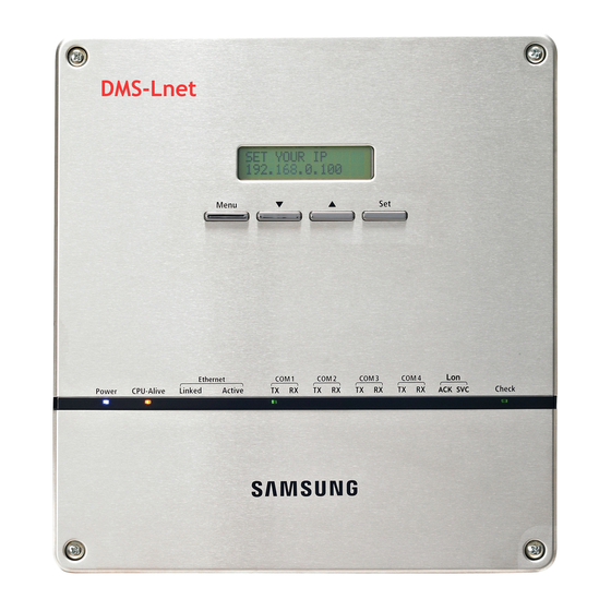
Viewing the Parts Main Parts LonWorks Gateway Exterior LCD Display Shows current time and IP address. Various messages will be displayed depending on button input. LCD operation button There are 4 buttons(Menu, (Down), (Up), Set) and you can access to menu and move, check the menu. - Page 8 LonWorks Gateway Cable Connection Part RS485 Communication Terminal DI Terminal1 DO Terminal3 DO Terminal4 DI Terminal2 Lon Terminal Reserved Serial Terminal Cable tie groove Power Terminal SD Card Socket Reset Button Ethernet Terminal Name Description DI Terminal1 Digital Input connection terminal, Channel1~Channel5 DI Terminal2 Digital Input connection terminal, Channel6~Channel10 DO Terminal3...
-
Page 9: Product Dimensions
Viewing the Parts (Continued) Main Parts LonWorks Gateway Interior Display Board 20-pin Cable LonWorks Board 2-pin Cable 10-pin Cable Main Board 40-pin Cable Sub Board Note If you need external circuit configuration, consult with the manufacturer. Product Dimensions 64.80 (Unit : mm) -
Page 10: System Architecture
System Architecture BMS system BMS Engineering Internet SAMSUNG Engineering LonWorks Gateway OnOff controller RS 485 Outdoor Unit Max 128 Indoor units (DVM Series) Connecting outdoor units and LonWorks Gateway - You can control up to 80 outdoor units and 128 indoor units using LonWorks Gateway. -
Page 11: Compatible Devices
Pulse Width: 20~400(ms) Pulse: 1~10000(Wh/Pulse) Products with ‘* ’ are not Samsung products and must be purchased separately. (Only selected power meters may be used for protocol compatibility issues.) Samsung is not responsible for BMS engineering which creates each device and objects. - Page 12 Maximum Devices Attachable Devices Max. Note Indoor Unit Tracking error occurs if exceeded OnOff Must not exceed 15 units per each RS485 controller communication terminal Must not exceed 16 units per each RS485 Outdoor unit communication terminal SIM/PIM Communication mode : IM Watt-hour Maximum 8 units can be connected to 1 SIM/PIM.
-
Page 13: Installing The Lonworks Gateway
Installing the LonWorks Gateway Separate the installation plate on the rear side of LonWorks Gateway. Fix the installation plate on the wall using 4 screws. Hang the LonWorks Gateway on the groove which is on the top of the installation plate. Installation plate... - Page 14 Fix the installation plate and LonWorks Gateway using 2 screws. If you install LonWorks Gateway inside of the wall or wiring from the rear side is needed, use wiring groove on the bottom of LonWorks Gateway. wiring groove To prevent breakdown and damage of LonWorks Gateway, and for safe usage, it is recommended to install LonWorks Gateway on the wall.
- Page 15 Installing the LonWorks Gateway (Continued) Connecting Outdoor unit Unfasten the 2 screws on the bottom of the LonWorks Gateway front cover. Hold the bottom 2 sides of the LonWorks Gateway and push downwards to slide open the cover. Connect the adapter to the power terminal. Arrange the adapter as the left figure.
- Page 16 Connecting SIM Unfasten the 2 screws on the bottom of the LonWorks Gateway front cover. Hold the bottom 2 sides of the LonWorks Gateway and push downwards to slide open the cover. Connect the adapter to the power terminal. Arrange the adapter as the right figure. Adapter Separate 1 terminal block from 5 terminal blocks which are attached to RS485 communication terminal.
- Page 17 Installing the LonWorks Gateway (Continued) Connecting LonWorks Unfasten the 2 screws on the bottom of the LonWorks Gateway front cover. Hold the bottom 2 sides of the LonWorks Gateway and push downwards to slide open the cover. Connect the adapter to the power terminal. Arrange the adapter as the left figure.
- Page 18 Commision Commision using Service Pin To activate the Service Pin, press and hold [SET] button for more than three seconds while time is displayed in the LCD Display window of the front side of LonWorks Gateway. Press and hold the [SET] button for more than 3 seconds.
- Page 19 Installing the LonWorks Gateway (Continued) Control and Monitoring Item Functional classification by a device. The functions provided can be different according to the type of the connected device. Remarks Indoor ERV AHU Kit NV Name 1 nviOnOff ON/OFF command 2 nviApplicMode Setting operating mode 3 nviSetpoint Setting desirable temperature...
- Page 20 Although the LonWorks Gateway can connect 128 units, the actual number of available items can differ according to the number of indoor units connected. When the number of indoor units is increased, the number of controllable items will be decreased; on the other hand, as the number of indoor units decreases, the controllable items increase.
-
Page 21: Setting The Lonworks Gateway
Setting the LonWorks Gateway LonWorks Gateway Connection and Login Address bar Click internet explorer icon( ) twice on your computer. When internet explorer window appears, enter IP address (http://192.168.0.100) on the address bar then press [ENTER]. If it is the first time to access LonWorks Gateway, “ Install Microsoft Silverlight”... - Page 22 Click [Run] button and continue installation. After installation, access to LonWorks Gateway again. Silverlight operates normally with Windows XP SP2 or later version. It may not operate normally with previous version of Windows.
- Page 23 Setting the LonWorks Gateway (Continued) Enter ID and password when LonWorks Gateway main web page appears, Then click [LOGIN]. If you use accounts with general authorization level to login, you cannot use the LonWorks Gateway settings. Depending on authorization level set by the administrator, access to some functions may be restricted.
- Page 24 If you login successfully, 'Control and Monitoring' screen of DMS2 will appear. Click [System Setting]➔[LonWorks configuration] menu to switch to LonWorks Gateway. If you use accounts with authorization level lower than management group or accounts with general authorization level, LonWorks configuration will not be displayed on the menu.
- Page 25 Setting the LonWorks Gateway (Continued) If you access LonWorks Gateway, 'Device Configuration' screen will appear initially. If you click [DMS2 Connect] button, screen will be switched to initial screen of the DMS2.
-
Page 26: Reading Ehp Watt-Hour Meter
Reading EHP Watt-hour Meter Setting and checking watt-hour meter Click [Setting and Checking Watt-hour meter]. You can change settings on watt-hour meter only when SIM interface module is connected. Click [Edit] from the 'Setting and checking Watt-hour meter' screen. CT proportion is set to ‘1’ as factory default value. Set the [Name] and [CT proportion] for the watt-hour meter. - Page 27 Reading EHP Watt-hour Meter (Continued) Monthly baseline setting Click [Setting and Checking Watt-hour meter]. Click [Edit] from the ‘Monthly baseline setting’ screen. You can make changes when list box enables. Set the Monthly baseline setting. You can select from 1~31. If you select the last day of the month, it will automatically set the last day of corresponding month as baseline.
- Page 28 Period setting Click [Setting and Checking Watt-hour meter]. Click [Edit] from the ‘Period setting’ screen. You can select checkbox to set period in daily or monthly unit. If you select daily period setting, text box will be enabled and you can enter the period in daily unit. If you select monthly period setting, you can select the period in monthly unit.
- Page 29 Reading EHP Watt-hour Meter (Continued) Channel setting by indoor unit Click [Channel setting by indoor unit]. Click [Edit] from the ‘Channel setting by indoor unit’ screen. Check the address and the channel information of the SIM/PIM interface module which is connected to the watt-hour meter. If the SIM/PIM interface modules with addresses 0 ~ 7 executes tracking, it will be displayed as 16~23 in LonWorks Gateway.
- Page 30 Check the SIM/PIM interface module channel (Watt-hour meter) information of indoor/outdoor unit. You can set the channel when SIM/PIM interface module is installed in LonWorks Gateway. When the indoor unit’s power is supplied from outdoor unit, set the ‘Outdoor unit SIM/PIM channel’...
-
Page 31: System Setting Initialization
System Setting Initialization Press [Menu], [ ], [ ] or [Set] from the screen where IP and current time is displayed. Main menu screen appears. Initialization is not possible in the screen where time information is displayed. Press [Menu] [ ] buttons in order from the main menu screen. -
Page 32: System Environment Setting
System Environment Setting You can set and check information about LonWorks Gateway installation and operation. LonWorks Gateway network information Click [System Environment Setting]. Click [Edit] from the ‘DMS network information’ section. When text boxes of IP, Subnet mask, Default gateway and DNS server are enabled. Enter values for each item. - Page 33 System Environment Setting (Continued) When the pop-up window appears, click [OK]. If you click [OK], current internet explorer will be closed. Then you may run the web browser again and access to LonWorks Gateway by entering the IP set and saved manually.
-
Page 34: System Time
System time Click [System Environment Setting]. Click [Edit] from the 'System time' section. Enter system time when text boxes enables. You can only enter numbers. Year: You can enter from 1980 to 2035. Month: You can enter from 1 to 12. Day: You can enter from 1 to 31. - Page 35 System Environment Setting (Continued) Selecting the language Click [System Environment Setting]. Click [Edit] from the 'Select language' section. Select a language you want and click [Save]. When the pop-up window appears, click [OK]. LonWorks Gateway will restart and the system will be changed to selected language.
- Page 36 LonWorks Gateway Name Setting Select [System Settings] menu and click [System environment setting]. Click [Edit] from LonWorks Gateway name setting window. Enter name of LonWorks Gateway when LonWorks Gateway name field enabled. You can use maximum 30 letters including English alphabets and special symbols.
- Page 37 System Environment Setting (Continued) Click [OK] when “This information will be modified. Do you want to proceed?” message window appears. “Reading data from LonWorks Gateway. Please wait. ” message appears and saving is completed. Afterwards, system environment setting screen appears again as all items are disabled.
- Page 38 Error Mail Forwarding Setting Click [System Settings]. Click [Edit] from error mail forwarding setting. Set all the items as the value you want when all items fields are enabled. If you select ‘Apply’ , you should enter e-mail address, SMTP server ID, password, and SMTP server address.
- Page 39 System Environment Setting (Continued) Click [OK] when “This information will be modified. Do you want to proceed?” message window appears. “Reading data from DMS2. Please wait. ” message appears and saving is completed. Afterwards, system environment setting screen appears again with all items are disabled. Note In factory setting, ‘Not apply’...
- Page 40 Setting Public IP of upper controller Select [System Settings] menu and click [System environment setting]. Click [Edit] when Public IP of upper controller screen appears. Enter the public IP of upper controller and select either ‘Apply’ or ‘Not apply’ . Click [Save].
- Page 41 System Environment Setting (Continued) Selecting the contact point control pattern Click [System Environment Setting]. Click [Edit] from the 'Select the contact point control pattern' section. Select the pattern you want to check when checkboxes enables. Pattern 1[No external input]: No operation will be made when inputting contact point control signal.
- Page 42 When the pop-up window appears, click [OK]. When message with “Reading data from DMS. Please wait” appears saving is completed. Then, 'System Environment Setting' screen appears again with all items disabled. Note Contact point control pattern is set to pattern 1 as factory default. For extension purpose, LonWorks Gateway has total of 10 DI/DO ports.
- Page 43 System Environment Setting (Continued) Contact point control pattern Pattern Control ▶ No external input (Factory default setting) Pattern1 When you input contact control signal in port 1, there will be no response. ▶ Level input (Emergency stop) 1. If the contact control signal is changed to ON, emergency stop status and all the indoor units are given ‘Stop’...
- Page 44 DI(Digital Input) Circuitry according to Control Switch Pattern Pattern 2 (May be used for connection with a fire sensor) Emergency Stop/Resume Operation No Connection Pattern 3 (External contact signal control) Operation/Stop A/C Enable/Disable remote control Pattern 4 (Pulse signal control) Operation Stop...
-
Page 45: Tracking
Tracking What is tracking? Tracking is an operation that finds devices connected to LonWorks Gateway. Through tracking operation, devices will be recognize if they are connected to LonWorks Gateway. To supervise and control system air conditioner using LonWorks Gateway, tracking should be done first. - Page 46 Setting communication mode for each channel Click [Device Configuration]. Click [Edit] from the 'Communication mode by channel' screen. [Edit] button will be switched to [Cancel]. All selection buttons will be enabled. However, the channels with searched device maintain its button in disabled status.
- Page 47 Tracking (Continued) When each channel is enabled, check the communication mode you want to set for each channel. You cannot change the communication mode of channel which has currently connected device. When ‘NEW’ is set as communication mode, setting will allow tracking, monitoring and controlling devices that support NEW communication mode.
- Page 48 DVM Tracking Click [Device Configuration]. Click [DVM Tracking].
- Page 49 Tracking (Continued) Enter administrator’s password. Click [OK]. Tracking information window pops up. Check it and click [OK] to continue. Execute tracking depending on the communication mode set by communication mode setting for each channel. ▶ Tracking will be executed only to the channels, which communication mode is set to either ‘NEW’...
- Page 50 Message will appear to alert that tracking is completed. Select the zone initializing mode and click [OK]. No initialization: No zone information initialization will be made. Individual initialization: Initialize zone information as individual mode. Group initialization: Initialize zone information as group mode. Page will be refreshed by clicking [OK].
-
Page 51: Device Configuration
Device Configuration Disconnect all devices Function Initialize searched device status in LonWorks Gateway. Monitoring and controlling of all the connected devices to LonWorks Gateway will be stopped when you use this function. ◆ Connect searched device to the other channel and execute tracking. If the other device is searched in the channel you want to use, use ‘Disconnect all devices’function. - Page 52 When the information window pops up, you must check the information and click [OK] to continue. When message with “Reading data from DMS. Please wait” appears and all the devices are disconnected, page will be refreshed. Note After executing 'Disconnect all device function' , device search status of LonWorks Gateway will be initialized.
- Page 53 Device Configuration (Continued) Checking and changing the Object ID List of equipment connected to LonWorks can be checked when the tracking is completed. Device Type, Address, Name and Object ID will appear. Object IDs are assigned in order from 1 to 128 when initial tracking is executed. If you want to change the Object ID, click [Edit] and change the Object ID of the applicable device.
- Page 54 Checking device information Click one of the Addresses from ‘Address’ colum. Detail information of the selected device will be displayed in device information. User can directly input and change the value of the input type information.
- Page 55 Device Configuration (Continued) Click [Edit] from the ‘Device Information’ screen. Enter the new value when the input field activates. When entering the new value, enter the value complying with NV type form. New value should be within the allowable range according to NV. Refer to LonWorks Message Definition for the input format and the allowable range.
- Page 56 Check the current value of the Output. The current value indicates the current status of indoor unit(ERV) and the value can be different due to synchronization delay with LonWorks MMI and data conversion. Refer to LonWorks Message Definition for device information display for each device.
-
Page 57: Overview For Function
Overview for Function Followings are the NV lists of indoor unit(ERV/AHU kit) supported by LonWorks Gateway. 1) nvi type - Data setting is allowed 2) nvo type - Data setting is not allowed Please refer to Message Definition for Setting value. 1. - Page 58 2. DMS system Objects NV Name NV Type Remarks nviDigitalOut[6] SNVT_ switch Control Digital output of DMS nviAllOff SNVT_hvac_emerg Control all indoor unit / ERV OFF nvoDigitalOut[6] SNVT_ switch Display Digital output status of DMS nvoDigitalIn[8] SNVT_ switch Display Digital input status of DMS nvoSystemLock SNVT_switch Display System Lock status of DMS...
-
Page 59: Network Parameter Chart
Network Parameter Chart Indoor/ERV/AHU kit objects SSACIndoor[nn](object id = 1-128) nvoSpaceTemp SNVT_temp_p nvoApplicMode nviOnOff SNVT_hvac_mode SNVT_switch nvoSetPoint nviApplicMode SNVT_temp_p SNVT_hvac_mode nvoOnOff nviSetPoint SNVT_switch SNVT_temp_p nvoFanStatus SNVT_switch nviFanStatus SNVT_switch nvoERVMode SNVT_count nviERVMode nvoErrorCode SNVT_count SNVT_count nviFilterReset nvoDeviceAlarm SNVT_switch SNVT_state nviUserLockout nvoOccOpMode SNVT_switch SNVT_switch nvoCoolTempLock... - Page 60 DMS system objects SSACSystem(object id = 129) nvoDigitalOut[6] SNVT_switch nviDigitalOut[6] SNVT_switch nvoDigitalIn[8] SNVT_switch nviAllOff SNVT_hvac_emerg nvoSystemLock SNVT_switch nvoDMSAlarm SNVT_count nvoSystemAlarm SNVT_count Configuration Properties nciSndHrtBt nciMinOutTm nciMinDeltaTemp nciDelayStatrup...
-
Page 61: Message Definition
Message Definition Data for Indoor Device nvoSpaceTemp(11) Description Indoor temperature SNVT_temp_p: Signed Long, 2 bytes SNVT Type Range: -10.00°C ~ 50.00°C Value and operation nvoApplicMode(12), nviApplicMode(2) Description Operation Mode status SNVT_hvac_mode: Enumeration(hvac_t) SNVT Type 0: HVAC_AUTO 1: HVAC_HEAT 3: HVAC_COOL Value and operation 6: HVAC_OFF 9: HVAC_FAN_ONLY... - Page 62 nvoFanStatus(15), nviFanStatus(4) Description Fan Speed and direction SNVT_switch: Unsigned/signed Short SNVT Type Value State Auto High Value and operation Turbo Auto Any>5.0 Stop Up-Down ❈ Supporting modes are different according to indoor units. - Indoor unit: Auto, Low, Mid, High - ERV : Mid, High, Turbo - AHU Kit: High * When an indoor unit operation mode is Auto or Dehumid,...
- Page 63 Message Definition (Continued) nvoDeviceAlarm(18) 1. Remote control restriction status 2. Filter alert status Description 3. Thermo On/Off status 4. Error alert Status SNVT_state: 16 Unsigned Bitfields SNVT Type Byte Bit9 Bit8 Operation Remark Unlock Flags_1 Level1 nvoUserLockout Lock Byte value Operation Remark Value and operation...
- Page 64 nvoHeatTempLock(21), nviHeatTempLock(10) Setting/monitoring upper limit temperature Description and function toggle SNVT_switch: Unsigned/signed Short SNVT Type Operation Value State Unlock 16.0 ~ 30.0 Value and operation Lock 16.0 ~ 30.0 Heat: 16.0°C ~ 30.0°C nvoEnergyConp(23) Description Electric consumption value within the period SNVT_elec_kwh_I: Signed Quad, 4bytes SNVT Type Raw range: 0 ~ 999999...
- Page 65 Message Definition (Continued) nviFilterReset(6) Description Filter alert reset SNVT_switch: Unsigned/singed Short SNVT Type Value State Operation remark Value and operation No Action 100.0 Filter Reset nviUserLockout(7), nvoUserLockout(22) Description Remote control restriction SNVT_switch: Unsigned/singed Short SNVT Type Value State Operation remark Unlock Value and operation 100.0...
- Page 66 Expansion of nvoDevListDesc desription character value Alphabet or digit Alphabet or digit Alphabet or digit Model information Alphabet or digit Alphabet or digit Alphabet or digit Separator Underbar(_) Alphabet or digit Centralized controller address Alphabet or digit Separator Period(.) [10] Alphabet or digit Interface Module address Alphabet or digit...
- Page 67 Message Definition (Continued) Data for DMS System nvoDigitalOut(3), nviDigitalOut(1) Description Digital output status on DMS SNVT_switch: Unsigned/singed Short SNVT Type Value State Value and operation 100.0 nvoDigitalIn(4) Description Digital Input status on DMS SNVT_switch: Unsigned/singed Short SNVT Type Value State Value and operation 100.0 nvoSystemLock(5)
- Page 68 nvoSystemAlarm(7) Description SIM/PIM Communication Error Code SNVT_count: Unsigned Long, 2 bytes SNVT Type SIM/PIM Communication Error Refer to list of Error code Value and operation nviAllOff(2) Description All indoor units turn off Enumeration, emerg_t SNVT Type 0 : EMERG_NORMAL Value and operation 4 : EMERG_SHUTDOWN...
- Page 69 Message Definition (Continued) Configuration Properties Overview This document provides information on all configuration properties defined for LonWorks Gateway device. For the sake of simplicity, although the configuration properties are defined to UFPTSSACSystem functional block, they are shared among the members of UFPTSSACIndoor functional blocks. Configuration Properties Table CPNV Name SCPT Reference...
- Page 70 Recommendations If required, set a value greater than the default update rate (currently, 10s). Any smaller value does not yield a change in the update pattern. Associate Values nvoSpaceTemp, nvoSetPoint Minimum Temperature Change This configuration property sets the minimum temperature change required before the associated output network variable is updated.
- Page 71 Memo...
Need help?
Do you have a question about the MIM-B18N and is the answer not in the manual?
Questions and answers