Siegenia KFV Assembly Instructions Manual
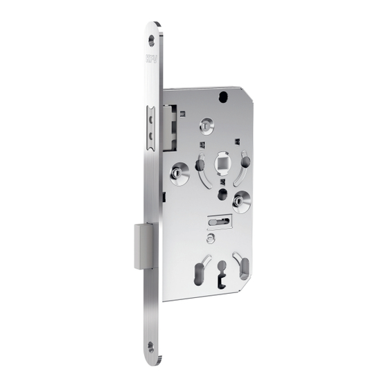
Magnetic lock
Hide thumbs
Also See for KFV:
- Assembly instructions manual (18 pages) ,
- Assembly instructions manual (16 pages) ,
- Operating instructions manual (16 pages)

Related Manuals for Siegenia KFV


Summary of Contents for Siegenia KFV
- Page 1 ASSEMBLY INSTRUCTIONS Magnetic lock Assembly instructions : Magnetic lock 111 Window systems Door systems Comfort systems...
-
Page 3: Table Of Contents
Contents Introduction Validity Target group of this documentation Correct use 1.3.1 Installation location 1.3.2 Locking part and hardware 1.3.3 Transport Improper use Care and service instructions Installation conditions and requirements Dimensions Explanation of symbols Instructions and symbols 1.10 Screw recommendation 1.11 Safety notices Overview... - Page 4 Introduction...
- Page 5 Introduction Magnetic lock 111 Lock • Based on DIN 18251-1 class 1 • For rebated interior doors • Quiet closing, pleasant acoustics • The latch does not hit the door frame • High-quality appearance thanks to flush latch position in gear box • With permanent magnets (neodymium) in the latch and striker plate • Brushed stainless steel secondary sash and striker plate • Also available as a pure latch lock...
-
Page 6: Introduction
• Do not attempt to repair the lock. If the lock is damaged, • Install hardware components and cylinder flush without it must be replaced by KFV or repaired by a service agent overtightening the screws or screwing them in at an angle. -
Page 7: Explanation Of Symbols
Introduction 1.8 Explanation of symbols Ø16 Milling cutter or drill diameter Timber (material of the door) 1.9 Instructions and symbols This symbol designates hazards that could damage the product or something in the surrounding area. This symbol indicates special features and designates facts that require increased attention. 1.10 Screw recommendation Face plate Striker plate... -
Page 8: Overview
Overview Overview 2.1 Product presentation PVC backing Striker plate Lock The striker plate is available in twelve versions: • With 2 or 3 fastening holes • With file latch entry • Without file latch entry • With striker plate opening • Without striker plate opening. -
Page 9: Component Dimensions
Overview 2.2 Component dimensions SSP 111-1/2-F/55-L (DIN left) WES 111-1/2-BB/55-L (DIN left) WES 111-1/2-WC/55-L (DIN left) Striker plate WC square nut 8 mm 05.2016... -
Page 10: Installation
Installation Installation 3.1 Cutting the door leaf Mark the holes for the handle set, according to Milling dimensions according to DIN 18101 DIN 18251-1: it is essential to dismount the gear box first. Metal filings could be attracted by the magnets of Remove any splinters from the lock mortise the latch, which could interfere with the functioning after milling. -
Page 11: Screw On The Magnetic Lock
Installation 3.2 Screw on the magnetic lock SSP 111-1/2-F/55-L (DIN left) according to DIN 18251-1 • Install hardware components and cylinder flush without overtightening the screws or screwing them in at an angle. • Mount the handle set according to the manufacturer´s instructions. -
Page 12: Changing The Hinge Side Of The Striker Plate
Installation 3.3 Changing the hinge side of the striker plate The magnet is marked on one side. This side must be pointing backwards in the striker plate. Click! -
Page 13: Milling The Door Frame
Installation 3.4 Milling the door frame 10 mm Ø16 Position of the striker plate upper edge of striker plate to centre of handle spindle 60 mm. 3.5 Mount the striker plate 05.2016... -
Page 14: Adjusting The Frame Parts
Installation 3.6 Adjusting the frame parts To ensure the smooth engagement of latch and deadbolt, adapt the recessed strike plate accordingly using a file. All dimensions are in mm... -
Page 15: Functional Test
Installation 3.7 Functional test Check the function of the deadbolt of the WC version: ► Turn the handle in the locking direction (90°). If the deadbolt does not return to its original position smoothly and completely, there is In order to check the functionality, the door and a functional disorder. - Page 16 A company of the SIEGENIA GROUP Phone: +49 2051 278-0 KFV Karl Fliether GmbH & Co. KG Fax: +49 2051 278-167 Siemensstraße 10 info@siegenia.com 42551 Velbert www.siegenia.com GERMANY Hungary Phone: +36 76 500810 SIEGENIA worldwide: Austria Phone: +43 6225 8301...
Need help?
Do you have a question about the KFV and is the answer not in the manual?
Questions and answers