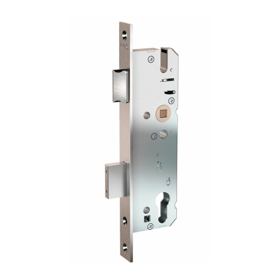
Siegenia KFV Assembly Instructions Manual
Hide thumbs
Also See for KFV:
- Assembly instructions manual (16 pages) ,
- Assembly instructions manual (18 pages) ,
- Operating instructions manual (16 pages)
Table of Contents

Subscribe to Our Youtube Channel
Summary of Contents for Siegenia KFV
- Page 1 ASSEMBLY INSTRUCTIONS Lock switch contact. W I N D O W H A R D WA R E D O O R H A R D WA R E S L I D I N G D O O R H A R D WA R E D O O R H A R D WA R E V E N T I L AT I O N T E C H N O LO G Y B U I L D I N G T E C H N O LO G Y...
- Page 2 Lock switch contact Assembly instructions...
-
Page 3: Table Of Contents
Assembly instructions Lock switch contact Contents Target group of this documentation Intended use Improper use Technical information on magnetic contacts Assembly Wiring diagram Function test Adjustment of the trigger contact magnet Adjustment of the frame parts Technical specifications Liability EU Declaration of Conformity... -
Page 4: Target Group Of This Documentation
• The lock switch contact is suitable for use in striker plates or locking rails with Q-adjustment in combination with KFV multi-point locks with hook bolts or pin-hook-bolt combination. • The lock switch contact is used in systems, e.g. alarm systems that provide feedback on the status of the door lock. -
Page 5: Technical Information On Magnetic Contacts
Assembly instructions Lock switch contact Technical information on magnetic contacts Lock switch contacts based on reed contact are sensitive to excessive voltage or currents. As reed contacts open their contact extremely quickly, very high self-induction voltages are generated when switching off inductive and capacitive switching devices such as e.g. relays. The lock switch contact must be protected here. - Page 6 Lock switch contact Assembly instructions Capacitive loads In contrast to inductive loads, increased inrush currents could occur with capacitive loads and lamp loads, which could lead to interference - including contacts possibly welding together. When charged capacitors are switched (e.g. also cable capacitors), a sudden discharge occurs, the intensity of which depends on the capacity and length of the supply line to the switch to be regarded as series resistor.
- Page 7 Assembly instructions Lock switch contact Direct current For switching of direct current, a free-wheeling diode must be connected in parallel to the load. The polarity must be accomplished out to ensure that the diode locks at the normal operating voltage and, on opening the switch, inversely short circuits occurring voltage peaks.
- Page 8 Lock switch contact Assembly instructions Magnetic switch test unit ZUPG0010 You can check the function of the magnetic contact and the NO or NC contacts with the aid of the magnetic switch ZUPG0010. To do this, connect the three cables of the magnetic contact to the connections 1-3 with the aid of the test terminals provided.
-
Page 9: Assembly
Assembly instructions Lock switch contact Assembly Unscrew the existing Q-adjustment Attention: You will also require screws and eccentric mandrels! Assembling a new lock switch contact 1. Mount the fixing plate... - Page 10 Lock switch contact Assembly instructions 2. Position the eccentric mandrels 3. Position the striker plates or locking rail 4. Screw on the striker plate or locking rail...
-
Page 11: Wiring Diagram
Assembly instructions Lock switch contact Wiring diagram Reed contact white burglar alarm transom Magnet system green brown Fig. 7 Wiring diagram Checking functionality On completion of the assembly, the dead bolt monitoring device must be checked for electrical switching function (e.g. with a multimeter or the test unit ZUPG0010). If the desired switching point is not reached immediately, the lock casing must be adjusted as described in the following pages (adjustment of the trigger contact). -
Page 12: Adjustment Of The Trigger Contact Magnet
Lock switch contact Assembly instructions Adjustment of the trigger contact magnet +/- 3 mm Fig. 8 Adjustment of the switch contact... -
Page 13: Adjustment Of The Frame Parts
Assembly instructions Lock switch contact Adjustment of the frame parts Fig. 9 Adjustment of the frame parts... -
Page 14: Technical Specifications
Lock switch contact Assembly instructions Technical specifications Cable LiYY 3 x 0.14 mm Protection class in accordance with DIN 40050 VdS environmental class III, IP 67 Contact type: Changeover contact Switching capacity max. 3 W / VA Switching voltage max. 30 V DC Switching current max. -
Page 15: Liability
EU Declaration of Conformity We, KFV KG, declare with full responsibility that this product complies with the provisions of Directives 2008/108/EC and 2006/95/EC of the Council of the... - Page 16 A company of the SIEGENIA GROUP KFV Karl Fliether GmbH & Co. KG Phone: +49 2051 278-0 Siemensstraße 10 Telefax: +49 2051 278-167 42551 Velbert info@kfv.de GERMANY www.kfv.de Hungary Phone: +36 76 500810 SIEGENIA worldwide: Austria Phone: +43 6225 8301...


Need help?
Do you have a question about the KFV and is the answer not in the manual?
Questions and answers