
Subscribe to Our Youtube Channel
Related Manuals for Siegenia KFV RB 1200


Summary of Contents for Siegenia KFV RB 1200
- Page 1 ASSEMBLY INSTRUCTIONS Multi-point service locks key-operated RB 1200 RB 1300 RB 1500 RB 1600 Window systems Door systems Comfort systems...
- Page 2 Assembly instructions Multi-point service locks, key operated RB 1200, RB 1300, RB 1500, RB 1600 2/50 02.2019 H39.MFVRS008EN-00...
-
Page 3: Table Of Contents
Assembly instructions Multi-point service locks, key operated RB 1200, RB 1300, RB 1500, RB 1600 Content INTRODUCTION .........4 6.6.2 Determining the position of the extension pieces .......... 25 Producer and Service ........4 Measuring and cropping the Target group of this documentation ..... 4 extension pieces .......... -
Page 4: Introduction
• Locking elements must not be misused to hold the KFV Karl Fliether GmbH & Co. KG door open. A company of the SIEGENIA GROUP • Movable or adjustable locking elements (e.g. dead- Siemensstraße 10 bolt, latch) must not be painted. -
Page 5: Transport
Assembly instructions Multi-point service locks, key operated RB 1200, RB 1300, RB 1500, RB 1600 te width, faceplate form, profile cylinder, handle Symbols used height, intervals of the auxiliary boxes (see chapter The following icons are used in this document: 3.2 „Application recommendations for RB 1200, RB 1300, RB 1500“... -
Page 6: Other Types Of Indicators
Assembly instructions Multi-point service locks, key operated RB 1200, RB 1300, RB 1500, RB 1600 Other types of indicators 1.10 Screw recommendations Below is a list of symbols used in these instructions and Non-stainless screws will cause corrosion of stainless their meanings: steel when they come into contact with stainless steel parts. -
Page 7: Aligning The Frame Parts And Main Lock In The Door
BS 220X/230X/250X and for the multi-point service lock RB 1600, download the operating instructions BS 260X from the download portal of our website www.siegenia.com. 1.13 Appropriate disposal The multi-point service lock and the optional accesso- ries should not be disposed of with household waste. -
Page 8: Safety
Assembly instructions Multi-point service locks, key operated RB 1200, RB 1300, RB 1500, RB 1600 Safety Before starting the assembly work, read the following safety instructions carefully. They are designed to keep you safe and prevent hazards, injuries and material damage. -
Page 9: Warning Notes
Assembly instructions Multi-point service locks, key operated RB 1200, RB 1300, RB 1500, RB 1600 Personal protective equipment CAUTION You will need the following protective equipment when The signal word "Caution" designates a potentially assembling multi-point service locks: hazardous situation. If this hazardous situation is not •... -
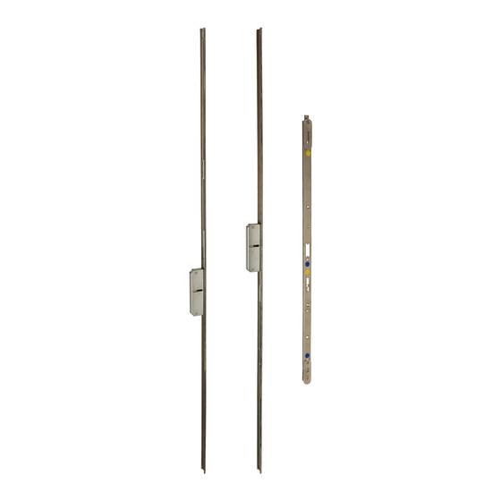
Page 10: Variants And Components
Assembly instructions Multi-point service locks, key operated RB 1200, RB 1300, RB 1500, RB 1600 Variants and components The multi-point service locks consist of a main lock set [1] (see chapter 3.1 „Main lock set (can be ordered sepa- rately)“ from page 11) and a secondary sash set [2] (consisting of two extension pieces, each with an auxiliary box and a Faceplate centre section for the main lock) that is available in four variants: H deadbolt [3], round bolt [4], hook bolt [5], round bolt/hook bolt combination [6]. -
Page 11: Main Lock Set (Can Be Ordered Separately)
(profile cylinder PZ or round cylinder RZ) and the PZ dimension. You can find more notes online at our homepage in the download area www.siegenia.com in the "Multi-point locks and frame parts" section. -
Page 12: Application Recommendations For Rb 1200, Rb 1300, Rb 1500
Assembly instructions Multi-point service locks, key operated RB 1200, RB 1300, RB 1500, RB 1600 Application recommendations for RB 1200, RB 1300, RB 1500 For secondary sash set RB 1200, RB 1300, RB 1500 key-operated, main lock type H and V (see chapter 4 „Main lock types, key-operated“... -
Page 13: Application Recommendation For Rb 1600
Assembly instructions Multi-point service locks, key operated RB 1200, RB 1300, RB 1500, RB 1600 Application recommendation for RB 1600 For secondary sash set RB 1600 key-operated, main lock type H and V (see chapter 4 „Main lock types, key-operated“ from page 14) 505 - 605 505 - 620 1260... -
Page 14: Main Lock Types, Key-Operated
Assembly instructions Multi-point service locks, key operated RB 1200, RB 1300, RB 1500, RB 1600 Main lock types, key-operated The faceplate sets and the main locks are identified by a coloured dot. Main lock types and their associated faceplate sets have the same colour coding. Variable dimensions in mm Locking Deadbolt... -
Page 15: Dimensions Of The Auxiliary Boxes
Assembly instructions Multi-point service locks, key operated RB 1200, RB 1300, RB 1500, RB 1600 Dimensions of the auxiliary boxes RB 1200 RB 1300 RB 1500 42,5 42,5 42,5 RB 1600 42,5 20,5 H39.MFVRS008EN-00 02.2019 15/50... -
Page 16: Installation
Assembly instructions Multi-point service locks, key operated RB 1200, RB 1300, RB 1500, RB 1600 Installation Dismantling defective multi-point lock Prior to dismantling the handle set, observe the assembly instructions of the producer. f Dismantle the handle set accor- ding to the assembly instruc- tions of the producer. - Page 17 Assembly instructions Multi-point service locks, key operated RB 1200, RB 1300, RB 1500, RB 1600 f Remove the square spindle of the lever handle from the hand- le nut. f Loosen all the fixing screws from the faceplate of the defective multi-point lock.
-
Page 18: Connecting The Main Lock To The Faceplate Centre Section
Assembly instructions Multi-point service locks, key operated RB 1200, RB 1300, RB 1500, RB 1600 Connecting the main lock to the faceplate centre section If you are using the existing cylinder lock, first use the key to check that the cylinder lock is working correctly. -
Page 19: Checking Functionality For The First Time
Assembly instructions Multi-point service locks, key operated RB 1200, RB 1300, RB 1500, RB 1600 Checking functionality for the first time f Place the cylinder lock [1] tem- porarily in position and secure it using the cylinder lock fixing screw [2]. f Check the functionality of the main lock based on the table on Page 20. - Page 20 Assembly instructions Multi-point service locks, key operated RB 1200, RB 1300, RB 1500, RB 1600 Test Malfunction Action Lock the deadbolt completely It must be possible for the dead- Deadbolt does not operate with • Check that the drive rods are correc- tly seated in the fastenings.
-
Page 21: Change Din Orientation Of The Soft Lock Latch Or Replace The Soft Lock Latch
Assembly instructions Multi-point service locks, key operated RB 1200, RB 1300, RB 1500, RB 1600 Change DIN orientation of the soft lock latch or replace the soft lock latch 1 x 5.5 mm There is a slot [1] on the gear box side. -
Page 22: Swing Door Roller Latch
Assembly instructions Multi-point service locks, key operated RB 1200, RB 1300, RB 1500, RB 1600 Swing door roller latch 6.5.1 Replace soft lock latch with swing door roller latch 1 x 5.5 mm There is a slot [1] on the gear box side. -
Page 23: Adjustment Of Swing Door Roller Latch
Assembly instructions Multi-point service locks, key operated RB 1200, RB 1300, RB 1500, RB 1600 6.5.2 Adjustment of swing door roller latch f Align the centre part of the swing door roller latch in such a way that the hole [1] is aligned with the faceplate fixing screws. -
Page 24: Arranging The Components Of The Multi-Point Service Lock
Assembly instructions Multi-point service locks, key operated RB 1200, RB 1300, RB 1500, RB 1600 Arranging the components of the multi-point service lock 6.6.1 Determining the position of the lock case f Place the dismantled multi-point lock [1] and the faceplate centre section with the mounted main lock [2] on a level surface. -
Page 25: Determining The Position Of The Extension Pieces
Assembly instructions Multi-point service locks, key operated RB 1200, RB 1300, RB 1500, RB 1600 6.6.2 Determining the position of the extension pieces f If possible, bring the defective multi-point lock and the main lock of the multi-point service lock into the release position. f Place the extension pieces [1] of the secondary sash set with the auxiliary boxes [3] next to the... - Page 26 Assembly instructions Multi-point service locks, key operated RB 1200, RB 1300, RB 1500, RB 1600 If the overlap of the toothed shoe and the drive rod is too short, this means the connection is not stable. This may cause the functions to become impaired or fail. The two overlap areas [4] (see figure Page 27) of the toothed shoe and the toothed drive rod must be at least 50 %.
- Page 27 Assembly instructions Multi-point service locks, key operated RB 1200, RB 1300, RB 1500, RB 1600 * Overlap areas are marked in blue H39.MFVRS008EN-00 02.2019 27/50...
-
Page 28: Measuring And Cropping The Extension Pieces
Assembly instructions Multi-point service locks, key operated RB 1200, RB 1300, RB 1500, RB 1600 Measuring and cropping the extension pieces CAUTION There is a risk of injury from sharp edges Cropping metal components creates sharp edges. This presents a risk of cutting injuries. -
Page 29: Checking The Groove Depth And Routed Pocket
Assembly instructions Multi-point service locks, key operated RB 1200, RB 1300, RB 1500, RB 1600 Checking the groove depth and routed pocket 6.8.1 Checking the groove depth on timber doors CAUTION Risk of injury from swarf flying around rapidly During milling work, there will be swarf flying around at high speed. Without protective equipment, this swarf can cause injuries, especially to the eyes. - Page 30 Assembly instructions Multi-point service locks, key operated RB 1200, RB 1300, RB 1500, RB 1600 Routed pocket for small auxiliary boxes (RB 1200/ RB 1300/ RB 1500): [1] 16 mm [2] 42.5 mm + 1 mm [3] 134 mm Routed pocket for large auxili- ary boxes (RB 1600): [1] 16 mm [2] 42.5 mm + 1 mm...
-
Page 31: Installing The Main Lock
Assembly instructions Multi-point service locks, key operated RB 1200, RB 1300, RB 1500, RB 1600 6.8.3 Installing the main lock f Check the thickness of the spindle [1]. If it is 8 mm thick, insert the enclosed reduction bush [2] into the spindle square of the main lock. -
Page 32: Functional Test Of The Main Lock
Assembly instructions Multi-point service locks, key operated RB 1200, RB 1300, RB 1500, RB 1600 Functional test of the main lock A functional disorder in the multi-point service lock may result in it no longer being able to open after locking. If a functionality check is performed on a closed door, it may be very difficult to open the door again without causing damage. -
Page 33: Check When The Door Is Closed
Assembly instructions Multi-point service locks, key operated RB 1200, RB 1300, RB 1500, RB 1600 6.9.2 Check when the door is closed Test Malfunction Action Check the movement of the latch into the frame part The latch must be able to run into the The latch runs with difficulty, does not •... -
Page 34: Insertion Of The Extension Pieces
Assembly instructions Multi-point service locks, key operated RB 1200, RB 1300, RB 1500, RB 1600 6.10.2 Insertion of the extension pieces f Angle the drive rod slightly away from the faceplate. Do not overstretch the drive rod. f Guide the toothed drive rod of the extension piece [1]onto the toothed shoe [2] at a right angle. - Page 35 Assembly instructions Multi-point service locks, key operated RB 1200, RB 1300, RB 1500, RB 1600 Note Distortion of the faceplate An excessively high screw tightening torque can cause deformation in the faceplate and, as a result, restrict the drive rods' freedom of movement.
-
Page 36: Checking Functionality After Each Extension Piece Has Been Assembled
Assembly instructions Multi-point service locks, key operated RB 1200, RB 1300, RB 1500, RB 1600 6.10.3 Checking functionality after each extension piece has been assembled Carry out a functionality check after every extension piece assembly . A functional disorder in the multi-point service lock may result in it no longer being able to open after locking. If a functionality check is performed on a closed door, it may be very difficult to open the door again without causing damage. -
Page 37: Adjustment Of Airgap
Assembly instructions Multi-point service locks, key operated RB 1200, RB 1300, RB 1500, RB 1600 6.12 Adjustment of airgap Observe the assembly and operating instructions for the door hinges. f In accordance with the enclosed assembly instruc- tions of the door hinge manufacturer, adjust the air gap [1] between the faceplate and striker plate or frame. -
Page 38: Adjustment Of At Piece
Assembly instructions Multi-point service locks, key operated RB 1200, RB 1300, RB 1500, RB 1600 6.13 Adjustment of AT piece When the door is closed, the latch must engage in the AT piece with as little play as possible. The AT piece [1] is horizontally adjustable for this purpose. - Page 39 Assembly instructions Multi-point service locks, key operated RB 1200, RB 1300, RB 1500, RB 1600 T 10 2.5 Nm f Tighten the two adjustment screws. f Close the door and check whether the latch engages properly. H39.MFVRS008EN-00 02.2019 39/50...
-
Page 40: Correct The Q Adjustment
Assembly instructions Multi-point service locks, key operated RB 1200, RB 1300, RB 1500, RB 1600 6.14 Correct the Q adjustment The Q adjustment is performed by moving two eccentric screws [1] laterally by ± 2.5 mm. This lateral adjustment changes the contact pressure of the door on the frame seal. - Page 41 Assembly instructions Multi-point service locks, key operated RB 1200, RB 1300, RB 1500, RB 1600 f Turn the two eccentric screws [1] to the left or right up to 90°. T 10 1.3 Nm f Tighten the three fixing screws of the Q adjustment firmly.
-
Page 42: Final Functional Test
Assembly instructions Multi-point service locks, key operated RB 1200, RB 1300, RB 1500, RB 1600 6.15 Final functional test A functional disorder in the multi-point service lock may result in it no longer being able to open after locking. If a functionality check is performed on a closed door, it may be very difficult to open the door again without causing damage. - Page 43 Assembly instructions Multi-point service locks, key operated RB 1200, RB 1300, RB 1500, RB 1600 Withdrawing the key f Turn the key to the withdrawal position and withdraw the key. The key must be able to be with- drawn with ease from the profile cylinder.
-
Page 44: Check When The Door Is Closed
Assembly instructions Multi-point service locks, key operated RB 1200, RB 1300, RB 1500, RB 1600 Retracting the locking elements f Turn the key in the unlocking direction with a double turn. The main lock bolt and the locking elements of the auxiliary boxes must retract completely and with ease. - Page 45 Assembly instructions Multi-point service locks, key operated RB 1200, RB 1300, RB 1500, RB 1600 Check the engaging of the locking elements f Turn the key in the locking direc- tion with a double turn. The main lock bolt and the locking elements of the auxiliary boxes must extend completely.
-
Page 46: Troubleshooting
Assembly instructions Multi-point service locks, key operated RB 1200, RB 1300, RB 1500, RB 1600 Troubleshooting Functional disorder of the lever handle The lever handle does not return to its original position by itself. f Check that the lever handle is correctly seated. •... -
Page 47: Skg Certified Assembly
Assembly instructions Multi-point service locks, key operated RB 1200, RB 1300, RB 1500, RB 1600 SKG certified assembly Screwing specifications for SKG certified frame parts Timber frames Lock casing for main lock 881-083 + 402-00031 C/D 3 pce. 4.5x45 mm 3 pce. -
Page 48: Assembly Specifications For Skg Certified Frame Parts
Assembly instructions Multi-point service locks, key operated RB 1200, RB 1300, RB 1500, RB 1600 Assembly specifications for SKG certified frame parts The dimensions for the vertical position must be exactly adhered to for the assembly of the frame parts. Consequently, it is ensured that the hook bolt can move fully into the locking position and achieve the specified minimum dimension for the grip into the frame part. - Page 49 Assembly instructions Multi-point service locks, key operated RB 1200, RB 1300, RB 1500, RB 1600 H39.MFVRS008EN-00 02.2019 49/50...
- Page 50 www.siegenia.com...
Need help?
Do you have a question about the KFV RB 1200 and is the answer not in the manual?
Questions and answers