
Related Manuals for SSV Works PHASE 5 X3-5K


Summary of Contents for SSV Works PHASE 5 X3-5K
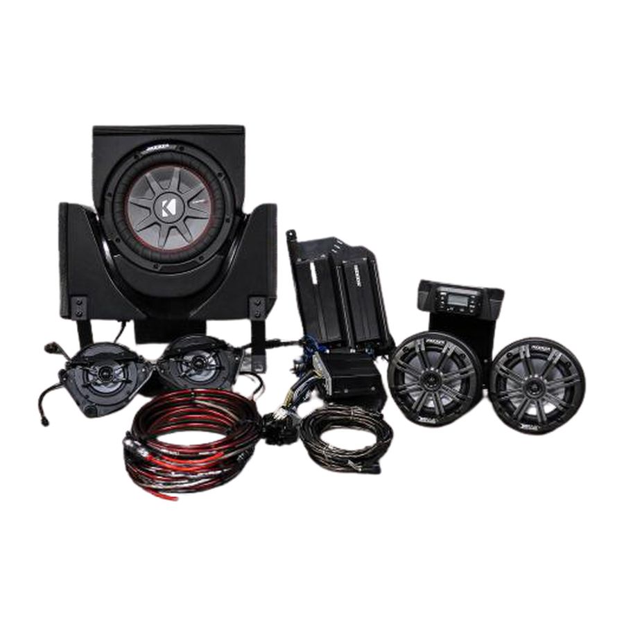
- Page 1 Disassembly, Wire and Amplifier Plate Installation Dash Kit Installation Underseat Subwoofer Installation Dash Speaker Pods Installation Cage Mount Speaker Pods Installation...
-
Page 3: Tools Needed For Installation
All SSV Works enclosures are covered by a limited lifetime warranty against defects in instructions completely before material or workmanship. All SSV Works Electronics are covered by a limited 1 year warranty installation to avoid possible injury, or against defects in material or workmanship. All SSV Works Speakers are covered by a damage to the accessory or vehicle. - Page 4 PANELS AND DASH DISASSEMBLY A. To remove the seat, use a 13mm socket and wrench to remove front (2) bolt and nut, and use a 18mm socket to remove (2) rear nuts and seat belt nut ( repeat on other seat) B.
- Page 5 PANELS AND DASH DISASSEMBLY E. Remove gas cover on the passenger side to expose a 10mm nut. Unscrew with a wrench and T30 torx driver. E2. Using panel removal tool unsnap (2) push clips on the driver and passenger side dash covers. Unscrew the (4) T30 screws on the passenger side, and (7) T30 screws on the driver side.
- Page 6 RUNNING AMP POWER CABLE AND SPEAKER WIRE WP-H16PG84-6 MRB3 Power Connector H. Connect the MRB3 Power into the WP-H16PG84-6. Using the butt splice terminals on the WP-H16PG84-6, connect black to black and red to yellow. I. In this step you will be feeding all of the necessary wires from the top drivers side dash down the center dash column. Be sure to run all of the wires along side the factory cabling to avoid any moving parts.
- Page 7 INSTALLATION NOTES AMP TRAY MODIFICATION WITH USE WITH AN AFTERMARKET ROLL CAGE 1. REMOVE THIS THREADED 2. IF NEEDED, INCREASE THE STUD BEFORE INSTALLAION OF DIAMETER OF THE HOLE TO THE AMP TRAY. GENTLY TAP OUT ACCOMMODATE THE ROLL THE THREADED STUD WITH A CAGE BOLT HAMMER.
- Page 8 AMP PLATE INSTALLATION K. From underneath driver side place amp plate between the two cross bars behind the steering wheel. L. Make sure the threaded bolt on the amp plate goes through the M. Secure the amp tray to the vehicle using the supplied M6 nut and factory hole located in the corner where the cage tubing connects.
- Page 9 AMP PLATE INSTALLATION P. Route the front B-H1149 speaker harness towards the driver and passenger side of the vehicle and leave the 4 pin connector at the driver side of dash (P1). Route the passenger side speaker wire under the center dash panel all the way to the passenger side speaker location (P2). Q.
- Page 10 USB/AUX INPUT PORT INSTALLATION S. Remove the (4) T30 torx on the front and inside of the glove box T. Remove push clips from underneath glove box. U. Pull up and remove the glove box. V. Drill a 1” hole through the left side of the glove box for wiring inside view inside view outside view...
-
Page 11: Parts List
All SSV Works enclosures are covered by a limited lifetime warranty against defects in instructions completely before material or workmanship. All SSV Works Electronics are covered by a limited 1 year warranty installation to avoid possible injury, or against defects in material or workmanship. All SSV Works Speakers are covered by a damage to the accessory or vehicle. - Page 12 A. Remove the factory rocker switches. B. Locate the two dimples at the top of the dash. These dimples are actual screw bosses on the underside of the dash. Line up base plate Drill pilot hole Drill 1/2” hole C. Rest the X3-DM3 base plate on the dash. Line up the two outside screw holes with the dimples of the dash. Do not screw the kit in yet. While holding the base plate down to the dash, use the center hole on the base plate to drill your 1/8”...
- Page 13 F. Now that the MRB3 remote is mounted to the dash kit route the din cable through the base plate so that it drops into the dash. Pull the din cable all the way through until the X3-DM3 Top Panel rests on the Base Plate. G.
- Page 15 All SSV Works enclosures are covered by a limited lifetime warranty against defects instructions completely before in material or workmanship. All SSV Works Electronics are covered by a limited 1 year installation to avoid possible injury, or warranty against defects in material or workmanship. All SSV Works Speakers are damage to the accessory or vehicle.
- Page 16 B. Using the supplied M6 screws and washers, screw the DD-brackets A. Apply the foam strips to the inside right, left and top side of to the bottom right and left side of the enclosure. the enclosure. C. Remove the factory 10mm nut and bolt from the brake line. Place the washer on top of the factory bracket and push the long M6x25mm screw through the top.
-
Page 17: Wiring Instructions
F. Place B-Bracket to the left side of the enclosure and slide the tab underneath the enclosure. (F1) Line up the 2 screw holes and proceed to hand thread the M6 screws and washers. Use a T30 Torx bit to tighten screws. Repeat for the right side. (F2) Line up the top of bracket A and B with the holes on the factory seat brakcet. - Page 19 All SSV Works enclosures are covered by a limited lifetime warranty against defects instructions completely before in material or workmanship. All SSV Works Electronics are covered by a limited 1 year installation to avoid possible injury, or warranty against defects in material or workmanship. All SSV Works Speakers are damage to the accessory or vehicle.
- Page 20 A. Remove the top dash panels on the driver (7 screws with 2 B. Pry off the (4) clips on the base under the empty space for the clips) and passenger side (5 screws with 2 clips). speaker C. Using a utility knife, cut off the (4) tabs fl ush to the panel D.
- Page 21 E. Place the acousic lens on top of the factory grille, line up F. Place the speaker pod under the dash panel and line up the the holes and insert the (2) top M6x1.0 (shorter) screws and holes on the speaker pod with the (2) top screws and loosely washers.
- Page 23 Labor for replacement of defective damage to the accessory or vehicle. components is not covered. All SSV Works Speakers are covered by a limited 1 year warranty against defects in material or workmanship. Contact SSV Works for further warranty information.
- Page 24 A. Find the best orientation for the speaker on your bar and B. Loosely install the clamp base to the cage mount pod with the screw in the Set Screws in the OPPOSITE holes of where the two (2) M6 hex head bolts and washers, place the cage mount clamp will install into.
- Page 25 D. Take the B-H1150 rear speaker harness and plug into the B-H1151 rear extension harness. E. Route the rear speaker harness (B-H1150) along the factory wires in the engine compartment and pull up through the small space between the bed panel and cage tubing on both passenger and driver sides. WIRING INSTRUCTIONS PXA 300.4 B-H1151...
- Page 26 C. Zip tie all wiring to the factory cables away from any moving parts. THIS CONCLUDES THE INSTALLATION PROCESS. REPLACE THE FACTORY PANELS AND SEATS. QUESTIONS? PLEASE CONTACT SSV WORKS AT 818-991-1778 OR EMAIL SUPPORT@SSVWORKS.COM © 2017 SSV Works, Oxnard, CA 93030...
Need help?
Do you have a question about the PHASE 5 X3-5K and is the answer not in the manual?
Questions and answers