Table of Contents
Advertisement
Quick Links
Advertisement
Chapters
Table of Contents

Subscribe to Our Youtube Channel
Related Manuals for Jungheinrich ECE 220 Standard


Summary of Contents for Jungheinrich ECE 220 Standard
- Page 1 ECE 220 04.04- Operating instructions 50435801 03.07...
- Page 2 Used to indicate standard equipment. Used to indicate optional equipment. Our trucks are subject to ongoing development. Jungheinrich reserves the right to alter the design, equipment and technical features of the truck. No guarantee of particular features of the truck should therefore be inferred from the present operating instructions.
-
Page 4: Table Of Contents
Table of contents Correct use and application of the truck Description of the truck Design and application ................ B 1 Assemblies ..................B 2 Technical data - standard version ............B 3 Performance data ................B 3 Dimensions ..................B 4 EN standards .................. - Page 5 Operation Safety regulations governing the operation of the fork lift truck ..E 1 Description of the operating controls and indicators ......E 2 Starting up the truck ................E 6 Operation of the fork lift truck .............. E 7 Safety regulations applicable when operating the truck ......
- Page 6 Appendix JH Traction Battery Operating Instructions These operating instructions apply only to Jungheinrich battery models. If using another brand, refer to the manufacturer's operating instructions.
-
Page 8: A Correct Use And Application Of The Truck
A Correct use and application of the truck The „Guidelines for the Correct Use and Application of Industrial Trucks“ (VDMA) are included in the scope of delivery for this truck. The guidelines are part of these oper- ating instructions and must always be heeded. National regulations are fully applica- ble. -
Page 10: B Description Of The Truck
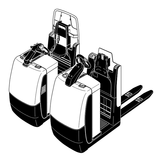
B Description of the truck Design and application The truck is an electric pallet truck in four-wheel version with driver stand and equip- ped with tiller-shaft steering or Jet Pilot (o). The truck is designed for use on level surfaces for transporting and order-picking goods. Pallets with open ground support or pallets fitted with lateral boards (provided that the boards are outside the range of the load-bearing wheels) can be picked up. -
Page 11: Assemblies
Assemblies 7, 8 Item Designation Item Designation t Front hood o Stop button t Battery hood o Forward “pedestrian / walk- along operation” button t Control shaft o Storage compartment t Master switch o Lift mechanism (emergency stop) t Controller t Jet Pilot t Brake key t Seat (XL version only) -
Page 12: Technical Data - Standard Version
Technical data - standard version Indication of technical data according to VDI 2198, subject to modification and supplementing. Performance data ECE 220 ECE 220 ECE 220 ECE 220 Designation Rapid Standard Rapid drive drive Q Rated capacity 2000 2000 2000 2000 Load centre distance with standard fork length *... -
Page 13: Dimensions
Dimensions (all dimensions in mm) Designation Standard Design length of front 1267 1434 Distance wheel <-> battery Length of driver standing plat- form Height of fork when lowered Lift Height of backrest “order-pick- 1867 1877 ing on 2nd level” Height of backrest without “or- 1255 1266 der-picking on 2nd level”... - Page 14 Working aisle widths ECE 220 Standard (all dimensions in mm) 1000 2267 1863 1000 2081 2467 1150 2417 2013 1200 2231 2667 1400 2667 2263 1214 1400 2481 2867 1400 2667 1891 1400 2109 2867 1450 2717 1941 1450 2159...
-
Page 15: En Standards
EN standards Continuous sound level: 69 dB(A) according to EN 12053 as stipulated in ISO 4871 The continuous sound level is a value averaged according to standard regulations, taking the sound pressure level into account when driving, lifting and idling. The sound pressure level is measured at the ear. -
Page 16: Identification Locations And Identification Plates
Identification locations and identification plates 2000 Item Model Truck data plate “Attention Touch Mode” warning decal *) for “Touch mode only in drive direction” option Accident prevention inspection label (Donly) Capacity Qmax / load distribution Attachment point of hooks for transportation by crane (inside) “Read operating instructions”... -
Page 17: Truck Identification Plate
Truck identification plate Item Designation Item Designation Type Manufacturer Serial No. Min./max. battery weight in kg Rated capacity in kg Drive power in kW Battery: Voltage V Load centre distance in mm Empty weight without battery in kg Year of manufacture Manufacturer logo Option In the event of queries relating to the truck or spare part orders, please state the serial... -
Page 18: C Transportation And Commissioning
C Transportation and commissioning Transportation by crane Only lifting gear of adequate ca- pacity must be used (for the transport weight, refer to the truck identification label). Lifting gear attachment points are provided on the chassis (1) and the fork (2) in case the truck is to be lifted or transported by crane. -
Page 19: Operating The Truck Without Its Own Drive System
Operating the truck without its own drive system This operating mode is not permitted when negotiating inclines and gradients. If the truck has to be moved after a failure has rendered it immobile, proceed as follows: – Set the isolator “OFF”. –... -
Page 20: D Battery - Servicing, Recharging, Replacement
D Battery - Servicing, recharging, replace- ment Safety regulations governing the handling of lead-acid batteries The truck must be parked and rendered safe before any operations on batteries are undertaken (refer to chapter E). Servicing staff: Recharging, servicing and replacing of batteries must only be per- formed by qualified personnel. -
Page 21: Battery Types
Battery types Depending on the use, the truck is equipped with different types of batteries. The table below shows the capacity of the batteries and also the combinations used as standard equipment: 24 V PzS battery 3 PzS 420 Ah L 24 V PzS battery performance-enhanced 3 PzS 450 Ah HX 24 V PzS battery... -
Page 22: Charging The Battery
Charging the battery To charge the battery, the truck must be parked in a closed and properly ventilated room. – Expose the battery (refer to section 3). The battery connector (4) and the charging cable (7) must only be connected or dis- connected with the truck and the battery charger switched off. -
Page 23: Removing And Installing The Battery
Removing and installing the battery The truck must be parked on level ground. To prevent short-circuits, batteries with ex- posed poles or cell connectors must be covered using a rubber mat. Place the battery connector or the battery cable, respectively, in such a way that they will not catch be- hind any truck protrusions when the battery is withdrawn. -
Page 24: Safety Regulations Governing The Operation Of The Fork Lift Truck
E Operation Safety regulations governing the operation of the fork lift truck Driving permission: The fork lift truck must only be operated by persons who have been trained in the operation of trucks, who have demonstrated to the user or his rep- resentative their capability of moving and handling loads, and who have expressly been charged by the user or his representative with the operation of the truck. -
Page 25: Description Of The Operating Controls And Indicators
Description of the operating controls and indicators Item Operating control or indicator Function t The circuit is interrupted, all electrical func- 1 Master switch (emergency stop) tions are switched off and the truck is auto- matically braked. t Gives an audible warning signal. 2 Operating key “Horn”... - Page 27 Item Operating control or indicator Function o Replaces the key switch. 12 Code lock Switches control voltage on and off. Releases the truck functions. o Code settings. Keyboard (CANCODE) Releasing and selecting the travel pro- grammes. Entering travel parameters. o Operating hours meter. 13 Display instrument (CANDIS) Battery capacity display.
-
Page 29: Starting Up The Truck
Starting up the truck Before starting or operating the truck, or before lifting any loads, the driver has to make sure that nobody is within the danger area. The electronic drive control system and the steering control system (option) are au- tomatically monitored for proper functioning. -
Page 30: Operation Of The Fork Lift Truck
Operation of the fork lift truck Safety regulations applicable when operating the truck Driving lanes and work areas: Only such lanes and routes that are specially allo- cated for truck traffic must be used. Unauthorized persons must stay away from work areas. -
Page 31: Driving, Steering, Braking
Driving, steering, braking Be extremely careful when driving and steering, especially when parts of the body protrude from the truck contour. The electric steering system is self-monitoring. The steering control systems monitors the fault frequency over a certain period. If the same fault is detected several times during this period, the steering control reduces the driving speed of the truck to low speed. - Page 32 Driving Do not drive the truck unless the hoods are closed and locked in the stipulated man- ner. – Start up the truck (refer to section 3). – Turn the controller (6) in the desired travelling direction: forward (V) or reverse (R). The truck will move in the selected direction.
- Page 33 Driving on inclines Loads must always be carried at that end of the truck facing uphill. Securing the truck against “rolling downhill”: With the controller (6) set to “0”, the service brake is automatically applied after a short jerk (the control system detects rolling downhill on an incline). The service brake is released again via the controller (6), which is also used to select the speed and the travelling direction.
- Page 34 Braking The braking behaviour of the truck strongly depends on the state of the floor. This must be taken into account by the driver for his driving behaviour. The truck may be braked in three ways: – using the service brake –...
-
Page 35: Pedestrian-Controlled Operation (O)
Pedestrian-controlled operation (o) When travelling in pedestrian-controlled mode you must make sure – while walking alongside – that the steering is set to straight travel and the operator cannot be trapped between the truck and an obstacle. In pedestrian-controlled mode the truck can be operated by the operator from all sides while he walking alongside. -
Page 36: Picking Up And Setting Down Loads
Picking up and setting down loads Before picking up a load, the driver has to make sure that it is correctly palletised and that the capacity of the truck is not exceeded. – Pass the lifting device as far as possible under the load. Picking up long loads crosswise is not permitted. -
Page 37: Order-Picking Up To The Second Level
Order-picking up to the second level The design of the operator position permits the operator, aided by the handles (18), to reach the step (19). Via the step (19) the driver can mount the battery hood (20), if needed. When order-picking operations are performed at the second level the operator must hold on to the handles (18) and not use the control shaft or Jet Pilot as support! No controls must be operated when engaged in order-picking activities. -
Page 38: Seat O (Xl Only)
Seat o (XL only) In folded-in position the seat (17) is integrated in the backrest. The folded-out seat allows the operator a convenient position while driving and operating. The seat can be adjusted in height and can be locked in four positions. –... -
Page 39: Keyboard (Cancode) (O)
Keyboard (CANCODE) (o) The operator keyboard is composed of 10 nume- ric keys, a Set key and an o-key. Activation of the travel programs by means of switches 1,2,3 is indicated by green LEDs. The o-key indicates operating conditions by a red/green LED. - Page 40 Commissioning After switching on the master switch and, if required, the key switch, the LED (21) lights up red. After entering the correct operator code (factory setting 2-5-8-0) the LED (21) lights up red. When an incorrect code has been entered, LED (21) lights up red for two seconds. After that you can enter a new code.
-
Page 41: Travel Programmes
Travel programmes By actuating the numeric keys 1, 2, and 3 you can select three travel programmes. The activated programme is indicated by the green LEDs (23), (24), (25) in the cor- responding key. The travel programmes differ with respect to travelling speed, acceleration, and de- celeration. -
Page 42: Parameter Settings
Parameter settings To change the truck settings the master code must be entered. The master code is factory-set to 7-2-9-5. Change the master code when setting the truck into operation for the first time (refer to section 5.1). Safety notes for trucks with indicator instrument (CANDIS (o)) –... - Page 43 Setting procedure for trucks with and without indicator instrument (CANDIS (o)): – Enter the three-digit parameter number and confirm with Set key (22). – The indicator instrument (CANDIS (o)) continues to display the operating hours. If the display changes, cancel the setting procedure with the o-key (26) and restart from the beginning.
- Page 44 Function Range Default Comments Setting value Setting Work flow value Code lock 002 Change operator code 0000 - 9999 (LED 23 flashes) Enter the current code 00000 - 99999 Confirm (Set) 000000 - 999999 (LED 24 flashes) Enter a new code Confirm (Set) (LED 25 flashes) Repeat the code en-...
- Page 45 Function Range Default Comments Setting value Setting val- Work flow Code lock 020 Start-up 0 - There is no start-up drive programme programme 1 - Drive programme 1 = start-up drive programme 2 - Drive programme 2 = start-up drive programme 3 - Drive programme 3 = start-up drive programme 021 Travel programme 1*...
-
Page 46: Travel Parameters
Travel parameters For trucks without indicator instrument (CANDIS (o)) the code lock parameters can only be set by the manufacturer's service. The following example shows the parameter setting for the acceleration of travel pro- gram 1 (parameter 101). Acceleration example Select the edited travel program after changing the parameter value, confirm with the Set key (22). - Page 47 During the parameter input the travel function is switched off. If the setting value is to be checked in programming mode, follow this sequence: – Select the edited travel program after changing the parameter value, confirm with the Set key (22). –...
- Page 48 Function Range Standard Comments Setting value Setting value Travel Programme 2 200 Acceleration in 0 - 9 Value of parameter pedestrian-controlled 201 >= Parameter operation 201 Acceleration in rider- 0 - 9 controlled operation 202 Coasting brake in rider- 0 - 9 controlled operation 203 Coasting brake in 0 - 9...
- Page 49 Function Range Standard Comments Setting value Setting value Travel Programme 3 300 Acceleration in 0 - 9 Value of parameter pedestrian-controlled 301 >= Parameter operation 301 Acceleration in rider- 0 - 9 controlled operation 302 Coasting brake in rider- 0 - 9 controlled operation 303 Coasting brake in 0 - 9...
- Page 50 Battery parameters For trucks without indicator instrument (CANDIS (o)) the code lock parameters can only be set by the manufacturer's service. The parameters are set in the same way as for the travel parameters. The following parameters can be entered: Function Range Standard...
-
Page 51: Display Instrument (Candis) (O)
Display instrument (CANDIS) (o) The instrument indicates: – Remaining battery charge (LED bars (28)), – Operating hours (LC display (30)). In addition, error messages of the electronic components and parameter changes are dis- played. Discharge status indication Depending on the battery type set, switch-on limits for the additional “Warning” (27) and “Stop”... -
Page 52: Discharge Monitor Function
Discharge monitor function With the discharge monitor function enabled, the lifting function switches of when reaching the discharge limit (the Stop LED switches on). Travelling and lowering is still possible. For wet batteries the residual capacity is 20%, for maintenance-free bat- teries it is 40%. -
Page 53: Fault Location
Fault location This chapter enables the operator to locate and rectify minor faults and malfunctions, or the effects of operating errors. When trying to locate a fault, proceed in the order shown in the table. Fault Possible cause Remedial action Truck –... -
Page 54: F Maintenance Of The Fork Lift Truck
F Maintenance of the fork lift truck Operational safety and environmental protection The checks and servicing operations contained in this chapter must be performed in accordance with the intervals as indicated in the servicing checklists. Modifications of fork lift truck assemblies, especially of the safety installations, are not permitted. - Page 55 Work on the electric system: Work on the electric system of the truck must only be performed by personnel specially trained for such operations. Before commencing any work on the electric system, all measures required to prevent electric shocks have to be taken. For battery-operated fork lift trucks, the truck must also be depow- ered by removing the battery plug.
-
Page 56: Servicing And Inspection
Servicing and inspection Thorough and expert servicing is one of the most important preconditions for safe op- eration of the fork lift truck. The neglect of regular servicing intervals can lead to fork lift truck failure and constitutes a potential hazard to personnel and equipment. The indicated servicing intervals are based on single-shift operation under normal op- erating conditions. -
Page 57: Maintenance Checklist
Maintenance checklist Maintenance intervals = t W A B C Standard Cold store Chassis/ 1.1 Check all load bearing elements for damage super- 1.2 Check all bolted connections structure: 1.3 Check platform for correct functioning and damage Drive unit: 2.1 Check the transmission for noises and leakage Wheels: 3.1 Check for wear and damage 3.2 Check the wheel bearings and ensure... - Page 58 Maintenance intervals = t W A B C Standard Cold store Battery: 9.1 Check acid density, acid level and cell voltage 9.2 Check the terminals for secure attachment and apply grease 9.3 Clean the battery connections; check for tight fitting 9.4 Check the battery cables for damage, renew if necessary Lifting 10.1 Check performance, wear and adjustment...
-
Page 59: Lubrication Schedule Ece 220
Lubrication schedule ECE 220 A + C 0,7 l B + C 1,4 l Gliding surfaces Grease nipples Filler plug for hydraulic oil Filler plug for gear oil Drain plug for gear oil Cold store usage Compound for cold store usage 1:1... -
Page 60: Fuels, Coolants And Lubricants
Fuels, coolants and lubricants Handling consumption type material: Consumption type material must always be handled properly. Manufacturer's instructions to be observed. Improper handling is injurious to health, life, and environment. Consumption type ma- terials must be stored in adequate containers. They might be inflammable and, there- fore, must not come into contact with hot components or open fire. -
Page 61: Instructions For The Servicing Operations
Instructions for the servicing operations Preparing the truck for the performance of servicing and maintenance opera- tions All required safety measures must be taken to prevent any accidents in the course of the servicing and maintenance operations. The following preparatory operations must be performed: –... -
Page 62: Removing The Front Hood
Removing the front hood – Open battery cover (refer to chapter D). – Remove the screws (5). – Lift front hood (4) and put aside. Installation occurs in the reverse order of steps. Do not drive the truck unless the hoods are closed and locked in the stipulated man- ner. -
Page 63: Checking The Electric Fuses
Checking the electric fuses – Prepare the truck for the servicing and maintenance operations (refer to section 6.1). – Remove the front hood (see section 6.3). – Referring to the table, check all fuses for correct rating and damage; replace fuses where required. -
Page 64: Recommissioning The Truck
Recommissioning the truck Recommissioning of the truck following the performance of cleaning or maintenance work is permitted only after the following operations have been performed: – Check the horn for proper functioning. – Check the master switch for correct functioning. –... -
Page 65: Recommissioning The Truck
Recommissioning the truck – Thoroughly clean the fork lift truck. – Lubricate the fork lift truck according to the lubrication chart (refer to chapter F). – Clean the battery. Grease the pole screws using pole grease and reconnect the battery. –... - Page 66 Jungheinrich traction battery Table of contents Jungheinrich traction battery ..........2-6 with positive tubular plates type EPzS and EPzB Type plate Jungheinrich traction battery..........7 Instruction for use ............8-12 Aquamatic/BFS III water refilling system Jungheinrich traction battery Maintenance free traction batteries with positive tubular plates type EPzV ....................13-17...
-
Page 67: Jungheinrich Traction Battery
Jungheinrich traction battery with positive tubular plates type EPzS and EPzB Rating Data 1. Nominal capacity C5: See type plate 2. Nominal voltage: 2,0 V x No of cells 3. Discharge current:: C5/5h 4. Nominal S.G. of electrolyte* Type EPzS:... - Page 68 Ignoring the operation instructions, repair with non-original parts or using additives for the electrolyte will render the warranty void. For batteries in classes I and II the instructions for maintaining the appropriate protection class during operation must be complied with (see relevant certificate). 1.
- Page 69 Battery container lids and the covers of battery compartments must be opened or re- moved. The vent plugs should stay on the cells and remain closed. With the charger switched off connect up the battery, ensuring that the polarity is cor- rect.
- Page 70 3. Maintenance 3.1 Daily Charge the battery after every discharge. Towards the end of charge the electrolyte level should be checked and if necessary topped up to the specified level with purified water. The electrolyte level must not fall below the anti-surge baffle or the top of the separator or the electrolyte „min“...
- Page 71 5. Storage If batteries are taken out of service for a lengthy period they should be stored in the fully charged condition in a dry, frost-free room. To ensure the battery is always ready for use a choice of charging methods can be made: 1.
-
Page 72: 7. Type Plate, Jungheinrich Traction Battery
7. Type plate, Jungheinrich traction battery Baujahr T ype Year of manufacture Serien-Nr. Lieferanten Nr. Serial-Nr. Supplier No. Nennspannung Kapazität Nominal V oltage Capacity Zellenzahl Batteriegewicht min/max Number of Cells Battery mass min/max Hersteller Jungheinrich AG, D-22047 Hamburg, Germany Manufacturer... -
Page 73: Aquamatic/Bfs Iii Water Refilling System
Aquamatic/BFS III water refilling system for Jungheinrich traction battery with EPzS and EPzB cells with tubular positive plates Aquamatic plug arrangement for the Operating Instructions Cell series* Aquamatic plug type (length) EPzS EPzB Frötek (yellow) (black) 2/120 – 10/ 600 2/ 42 –... - Page 74 Diagrammatic view Equipment for the water refilling system 1. Water tank 2. Level switch 3. Discharge point with ball valve 4. Discharge point with sole- noid valve 5. Charger 6. Sealing coupler 7. Closing nipple 8. Ion exchange cartridge with conductance meter and solenoid valve 9.
- Page 75 4. Filling (manual/automatic) The batteries should be filled with battery water as soon as possible before the battery charging comes to an end; this ensures that the refilled water quantity is mixed with the electrolyte. In normal operation it is usually sufficient to fill once a week. 5.
- Page 76 8. Battery hose connections Hose connections for the individual plugs are laid along the existing electric circuit. No changes may be made. 9. Operating temperature The temperature limit for battery operation is set at 55° C. Exceeding this temperature damages the batteries. The battery filling systems may be operated within a tempe- rature range of >...
- Page 77 10.2.1 Clamping ring tool The clamping ring tool is used to push on a clamping ring to increase the contact pres- sure of the hose connection on the plugs' hose couplings and to loosen it again. 10.3 Filter element For safety reasons a filter element (ident no.: 50307282) can be fitted into the batte- ry's main supply pipe for supplying battery water.
-
Page 78: Jungheinrich Traction Battery
Jungheinrich traction batterie Maintenance free Jungheinrich traction batterie with positive tubular plates type EPzV and EPzV-BS Rating Data 1. Nominal capacity C5: See type plate 2. Nominal voltage: 2,0 Volt x No of cells 3. Discharge current: C5/5h 4. Rated temperature: 30°... - Page 79 Ignoring the operation instructions, repair with non-original parts and non authorised interventions will render the warranty void. For batteries in classes I and II the instructions for maintaining the appropriate protection class during operation must be complied with (see relevant certificate). 1.
- Page 80 With the charger switched off connect up the battery, ensuring that the polarity is cor- rect (positive to positive, negative to negative). Now switch on the charger. When charging the temperature of the battery rises by about 15° C, so charging should only begin if the battery temperature is below 35°...
- Page 81 3.2 Weekly Visual inspection after recharging for signs of dirt and mechanical damage. 3.3 Quarterly After the end of the charge and a rest time of 5 h following should be measured and recorded: • the voltages of the battery •...
-
Page 82: 7. Type Plate, Jungheinrich Traction Battery
Batteries with this sign must be recycled. Batteries which are not returned for the recycling process must be disposed of as hazardous waste! We reserve the right make technical modification. 7. Type plate, Jungheinrich traction battery Baujahr T ype Year of manufacture Serien-Nr.
Need help?
Do you have a question about the ECE 220 Standard and is the answer not in the manual?
Questions and answers