Jungheinrich EJC 112 Operating Instructions Manual
Hide thumbs
Also See for EJC 112:
- Operating instruction (211 pages) ,
- Operating instructions manual (87 pages)
Table of Contents
Advertisement
Advertisement
Table of Contents

Subscribe to Our Youtube Channel
Related Manuals for Jungheinrich EJC 112


Summary of Contents for Jungheinrich EJC 112
- Page 1 EJC 110/112 01.05 - Operating instructions 50444126 03.07...
- Page 2 Used to indicate standard equipment. Used to indicate optional equipment. Our trucks are subject to ongoing development. Jungheinrich reserves the right to alter the design, equipment and technical features of the truck. No guarantee of particular features of the truck should therefore be inferred from the present operating instructions.
-
Page 4: Table Of Contents
Index Correct use and application Truck Description Application ................... B 1 Assemblies ..................B 2 Standard Version Specifications ............B 3 Performance data for standard trucks ..........B 3 Dimensions ..................B 3 EN norms .................... B 5 Conditions of use ................B 5 Identification points and data plates ............ - Page 5 Operation Safety Regulations for the Operation of Forklift Trucks ...... E 1 Controls and Displays ................. E 2 Starting up the truck ................E 6 Using the industrial truck ..............E 7 Safety regulations for truck operation ..........E 7 Travelling, Steering, Braking ...............
- Page 6 Appendix JH Traction Battery Operating Instructions These operating instructions apply only to Jungheinrich battery models. If using another brand, refer to the manufacturer's operating instructions.
-
Page 8: A Correct Use And Application
A Correct use and application The “Guidelines for the Correct Use and Application of Industrial Trucks” (VDMA) are supplied with the truck. The guidelines form part of these operating instructions and must be observed. National regulations apply in full. The truck described in the present operator manual is an industrial truck designed for lifting and transporting load units. -
Page 10: B Truck Description
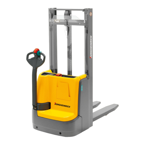
B Truck Description Application The EJC is a four wheel, tiller guided electric truck with a steered drive wheel. It is designed for use on level floors to lift and transport palletised goods. Open bottom pallets or roll cages can be lifted. The capacity can be obtained from the data plate. -
Page 11: Assemblies
Assemblies Item EJC 110 EJC 112 Description Switch switch CANCODE keypad ISM Access Module Battery discharge indicator /hourmeter CANDIS display instrument Tiller and grip “Shunt” switch Controller Collision safety switch Mast Mast guard Battery panel Battery connector (emergency disconnect) Lift mechanism... -
Page 12: Standard Version Specifications
Standard Version Specifications Technical specification details in accordance with VDI 2198. Technical modifications and additions reserved. Performance data for standard trucks Description EJC 110 EJC 112 Q Rated capacity 1000 1200 C Load centre distance Standard fork length Travel speed 6.0 / 6.0... -
Page 14: Norms
EN norms Noise emission: 70 dB(A) in accordance with EN 12053 as harmonised with ISO 4871. The noise emission level is calculated in accordance with standard procedures and takes into account the noise level when travelling, lifting and when idle. The noise level is measured at the driver’s ear. -
Page 15: Identification Points And Data Plates
Identification points and data plates Item Description Capacity Truck data plate Attachment point for lifting by crane (with ZZ mast in the middle) "Do not reach through the mast" warning “Do not step under the load handler” warning Battery data plate “No passengers”... -
Page 16: Truck Data Plate
Truck data plate Item Description Item Description Type Manufacturer’s logo Serial no. Min./max. battery weight (kg) Rated capacity (kg) Output (kW) Battery voltage (V) Load centre of gravity (mm) Net weight excl. battery Year of manufacture Manufacturer Option For queries regarding the truck or ordering spare parts please quote the truck serial number (28). -
Page 17: Capacity Plate, Order, Inventory And Service Nos
Capacity plate, Order, Inventory and Service Nos. Item Description Order no. Inventory no. Full Service No. The capacity plate with the full service number is only issued when a service agreement has been reached. -
Page 18: C Transport And Commissioning
C Transport and Commissioning Lifting by crane Only use lifting gear with sufficient capacity (for transport weight see truck data plate). The attachment points (1) are provided for lifting the truck with crane lifting gear (in the middle with the ZZ mast). –... -
Page 19: Operating The Truck Without Its Own Drive System
Operating the truck without its own drive system This operating mode is not permitted when negotiating inclines and gradients. To operate the truck in emergency conditions, the electromagnetically applied brake must be released. – Remove the front panel (2) (see Chapter F). –... -
Page 20: D Battery Maintenance, Charging & Replacement
D Battery Maintenance, Charging & Replacement Safety regulations for handling acid batteries Park the truck securely before carrying out any work on the batteries (see Chapter E). Maintenance personnel: Batteries may only be charged, serviced or replaced by trained personnel. The present operator manual and the manufacturer’s instructions concerning batteries and charging stations must be observed when carrying out the work. -
Page 21: Battery Types
Battery types Depending on the model, the EJC comes with different battery types. The battery weights can be taken from the battery data plate. When replacing or installing batteries, ensure that the battery is correctly secured in the battery compartment of the truck. The following table shows which combinations are included as standard: Chassis version Truck type... -
Page 22: Charge The Battery
Charge the battery The EJC 110/112 is fitted as standard with an onboard charger (for charging see section 4.1). The EJC 110/112 can optionally be fitted with a stationary charger (for charging see section 4.2). To charge the battery, the truck must be parked in a closed and properly ventilated room. - Page 23 Maintenance-free: 200 - 300 Ah Wet cell batteries: 200 - 400 Ah pulse characteristic Wet cell batteries: Jungheinrich 100 - 300 Ah All other switch (4) positions block the charger, and the battery is not charged. Setting the charging characteristic curve...
- Page 24 Starting to charge with the onboard charger – Park the truck securely (see Chapter E). When charging, the tops of the battery cells must be exposed to provide sufficient ventilation. Do not place any metal objects on the battery. Before charging, check all cables and plug connections for visible signs of damage.
- Page 25 The flashing LED indicates the charge status or a fault (for flashing codes see “LED Display” table). If the mains connector (5) is connected to the mains, all the truck’s electrical functions will be interrupted (electrical start block). The truck cannot be operated. –...
-
Page 26: Charging The Battery With A Stationary Charger O
Charging the battery with a stationary charger o – Park the truck securely (see Chapter E). Only connect and disconnect the battery connector and the socket when the mains and charger are switched off. – Expose the battery (see Section 3). When charging, the tops of the battery cells must be exposed to provide sufficient ventilation. -
Page 27: Battery Removal And Installation
Battery removal and installation – Undo the spring elements of the battery panel and remove the battery panel. The truck must be parked on level ground. To prevent short circuits, batteries with exposed terminals or connectors must be covered with a rubber mat. Place the battery connector or the battery cable in such a way that they will not get caught on the truck when the battery is removed. -
Page 28: Battery Discharge Indicator (T)
Battery Discharge Indicator (t) When the truck has been released via the keyswitch or CANCODE, the battery charge status is displayed. The colours of the LEDs (8) represent the following conditions: LED colour Rating Green Standard battery residual capacity 40 - 100 % Maintenance free battery residual capacity 60 - 100 % Orange... - Page 29 D 10...
-
Page 30: Safety Regulations For The Operation Of Forklift Trucks
E Operation Safety Regulations for the Operation of Forklift Trucks Driver authorisation: The forklift truck may only be used by suitably trained personnel, who have demonstrated to the proprietor or his representative that they can drive and handle loads and have been authorised to operate the truck by the proprietor or his representative. -
Page 31: Controls And Displays
Controls and Displays Item Control / EJC 110 EJC 112 Function Display Battery connector The circuit is interrupted, all electrical functions are cut out. The (Emergency Stop) truck automatically brakes. Switch switch Switches control current on and off. Removing the key prevents the truck from being switched on by unauthorised personnel. - Page 33 Item Control / EJC 110 EJC 112 Function Display Controller Controls travel direction and speed. Collision safety Truck moves away from the operator switch and stops. Load fork raise Raises load forks. switch The lift speed can be infinitely controlled via the switch stroke (8 mm).
-
Page 35: Starting Up The Truck
Starting up the truck Before the truck can be commissioned, operated or a load unit lifted, the driver must ensure that there is nobody within the hazardous area. Checks and operations to be performed before starting daily work – Visually inspect the entire truck (in particular wheels and load handler) for obvious damage. -
Page 36: Using The Industrial Truck
Using the industrial truck Safety regulations for truck operation Travel routes and work areas: Only use lanes and routes specifically designated for truck traffic. Unauthorised persons must stay away from work areas. Loads must only be stored in places specially designated for this purpose. Driving conduct: The driver must adapt the travel speed to local conditions. -
Page 37: Travelling, Steering, Braking
Travelling, Steering, Braking Never carry passengers. Emergency Stop – Remove the battery connector (1). All electrical functions are deactivated. Automatic braking Automatic braking occurs when the tiller is released – the tiller automatically sets itself to the upper brake zone (B). If the tiller moves slowly to the upper brake zone, the cause of this fault must be rectified. - Page 38 Crawl speed The driver must be particularly careful when applying the “Crawl speed” switch (6). The truck can be operated with a vertical tiller (5) (e.g. in congested areas / travel seat). – Press the crawl speed switch (6). – Set the travel switch (7) to the required direction (fwd. or rev.). The brake is released.
- Page 39 Braking The braking pattern of the truck depends largely on the track conditions. The driver must take this into account when operating the truck. Braking with the Service Brake: – Set the tiller (5) up or down to one of the brake zones (B).
-
Page 40: Collecting And Depositing Loads
Collecting and depositing loads Before lifting a load, the driver must ensure that it is correctly palletised and that the capacity of the truck is not exceeded. – Drive the truck with forks as far as possible underneath the load. With the two-stage Duplex mast (ZZ) a short, centre-mounted free lift cylinder initially lifts the load carriage (free lift) without changing the overall height of the truck. -
Page 41: Emergency Lowering
Emergency lowering Keep all personnel out of the hazardous area when applying emergency lowering. If the mast cannot be lowered any further due to a fault in the combination controller, manually apply the valve (14) on the hydraulic unit. – Set key switch (2) to “0”. –... -
Page 42: Parking The Truck Securely
Parking the truck securely When you leave the truck it must be securely parked even if you only intend to leave it for a short time. Do not park the truck on a slope. The load forks must always be lowered to the ground. - Page 43 Starting the truck for the first time The LED (15) goes red when you connect the battery and if necessary switch on the key switch. When you enter the correct operator code (factory setting 2-5-8-0) the LED (15) turns green. If the wrong code is entered LED (15) flashes red for two seconds.
-
Page 44: Travel Programs
Travel programs Press the digit keys 1, 2, and 3 to select any of three travel programs. The activated program is indicated by the green LEDs (17), (18), (19) in the corresponding key. The travel programs differ with respect to travel speed, acceleration and deceleration force. -
Page 45: Parameter Settings
Parameter Settings To change the truck setting you must enter the master code. The factory setting for the master code is 7-2-9-5. When starting the truck for the first time, change the master code. Safety instructions for trucks with a display instrument (CANDIS (o)) –... - Page 46 Setting procedure for trucks with and without display instrument (CANDIS (o)): – Enter the three digit parameter number, confirm with the Set key (16). – The display instrument (CANDIS (o)) continues to display the operating hours. If the display changes, cancel the setting with the o-key (20) and restart from the beginning.
- Page 47 Function Setting Range Standard Comments Setting Procedure Code Lock 002 Change Operator Code 0000 - 9999 (LED 17 flashes) Enter current code 00000 - 99999 Confirm (Set) 000000 - 999999 (LED 18 flashes) Enter new code Confirm (Set) (LED 19 flashes) Repeat code entry confirm...
- Page 48 Function Setting Range Standard Comments Setting Procedure Code Lock 020 Start travel program 1 - 3 1 = Travel program 1 2 = Travel program 2 3 = Travel program 3 021 Travel program 1 0 or 1 0 = Travel program Enable not enabled 1 = Travel program...
-
Page 49: Travel Parameters
Travel parameters For trucks without a display instrument (CANDIS (o)) the code lock parameters can only be set by the manufacturer's service department. The following example shows the parameter setting for the acceleration of travel program 1 (parameter 101). Acceleration example Display instrument LED (20) LED (17) - Page 50 The following parameters may be entered. Travel programs Function Setting Range Standard Comments Setting Travel program 1 101 Acceleration 0 - 9 (0.2 - 2.0 m/s 0.4 m/s 102 Coasting brake 0 - 9 (0.2 - 1.1 m/s (0.5 m/s 104 Maximum speed in drive 0 - 9 depending on...
- Page 51 Function Setting Range Standard Comments Setting Travel program 3 301 Acceleration 0 - 9 (0.2 - 2.0 m/s (1.0 m/s 302 Coasting brake 0 - 9 (0.2 - 2.0 m/s 0.8 m/s 304 Maximum speed in tiller 0 - 9 depending on direction via travel switch controller...
-
Page 52: Display Instrument (Candis) (O)
Display instrument (CANDIS) (o) The instrument indicates: – Battery residual charge status (LED bars (22)), – Service hours (LC display (24)). In addition, service messages for the elec- tronic components and parameter changes are displayed. Discharge status indication Setting limits for the additional “Warning” (21) and “Stop” (23) displays will depend on the battery type set. -
Page 53: Discharge Monitor Function
Discharge monitor function When the discharge monitor function is enabled, lifting is cut out when reaching the discharge limit is reached (the Stop LED goes on). Travel and lowering are still possible. For wet batteries the residual capacity is 20%, for maintenance-free batteries it is 40%. -
Page 54: Troubleshooting
Troubleshooting This chapter is designed to help the user identify and rectify basic faults or the results of incorrect operation. When locating a fault, proceed in the order shown in the table. Fault Possible cause Action Truck does not – Battery plug not connected. –... - Page 55 E 26...
-
Page 56: F Forklift Truck Maintenance
F Forklift Truck Maintenance Operational safety and environmental protection The servicing and inspection operations contained in this chapter must be performed in accordance with the intervals indicated in the servicing checklists. Any modification to the forklift truck assemblies, in particular the safety mechanisms, is prohibited. - Page 57 Electrical System: Only suitably trained personnel may operate on the truck’s electrical system. Before working on the electrical system, take all precautionary measures to avoid electric shocks. For battery-operated trucks, also de-energise the truck by removing the battery connector. Welding: To avoid damaging electric or electronic components, remove these from the truck before performing welding operations.
-
Page 58: Servicing And Inspection
Servicing and inspection Thorough and expert servicing is one of the most important requirements for the safe operation of the industrial truck. Failure to perform regular servicing can lead to truck failure and poses a potential hazard to personnel and equipment. The service intervals stated are based on single shift operation under normal operating conditions. -
Page 59: Maintenance Checklist
Maintenance Checklist Maintenance intervals Standard = W A B C Chassis/ 1.1 Check all load bearing components for damage Structure: 1.2 Check screw connections Drive: 2.1 Check transmission for noise and leakage 2.2 Check transmission oil level 2.3 Change transmission oil Wheels: 3.1 Check wheels for wear and damage 3.2 Check the bearings and attachment... - Page 60 Maintenance intervals Standard = W A B C Electrical 8.1 Test operation System: 8.2 Make sure wire connections are secure and check for damage 8.3 Check fuse ratings 8.4 Test operation of switches and trip cams and make sure they are secure 8.5 Check contactors and relays;...
-
Page 61: Ejc 110/112 Maintenance Schedule
EJC 110/112 Maintenance Schedule 0,55 l Contact surfaces Hydraulic oil filler neck Hydraulic oil drain plug Transmission oil filler neck Transmission oil overflow and control screw Transmission oil drain plug... -
Page 62: Fuels, Coolants And Lubricants
Fuels, coolants and lubricants Handling consumables: Consumables must always be handled correctly. Follow the manufacturer’s instructions. Improper handling is hazardous to health, life and the environment. Consumables must only be stored in appropriate containers. They may be flammable and must therefore not come into contact with hot components or naked flames. -
Page 63: Maintenance Instructions
Maintenance Instructions Prepare the truck for maintenance and repairs All necessary safety measures must be taken to avoid accidents when carrying out maintenance and repairs. The following preparations must be made: – Park the truck securely (see Chapter E). – Disconnect the battery (1) to prevent the truck from accidentally starting. When working under a raised lift truck, secure it to prevent it from tipping or sliding away. -
Page 64: Checking The Hydraulic Oil Level
Checking the hydraulic oil level – Prepare the truck for maintenance and repairs (see Chapter 6.1). – Remove the front panel (see section 6.2). – Check hydraulic oil level in hydraulic reservoir. There are markings on the hydraulic reservoir. The oil level must be checked when the load forks are lowered. -
Page 65: Flushing The Gauze Filter, Replacing The Gauze Filter
Flushing the gauze filter, Replacing the gauze filter – Prepare the truck for maintenance and repairs (see Section 6.1). – Remove the front panel (see Section 6.2). – Undo the union (8). – Remove connection and take out the gauze filter –... -
Page 66: Checking Electrical Fuses
Checking electrical fuses – Prepare the truck for maintenance and repairs (see Section 6.1). – Remove the front panel (see Section 6.2). – Check the fuse rating and condition in accordance with the table; replace if necessary. Item To protect: EJC 110/112 Overall control fuse F1 10 A... -
Page 67: Recommissioning
Recommissioning The truck may only be recommissioned after cleaning or repair work, once the following operations have been performed. – Test horn. – Test EMERGENCY DISCONNECT switch. – Test brake. – Lubricate the truck in accordance with the maintenance schedule. Decommissioning the industrial truck If the industrial truck is to be decommissioned for more than two months, e.g. -
Page 68: Restoring The Truck To Operation After Decommissioning
Restoring the truck to operation after decommissioning – Thoroughly clean the truck. – Lubricate the truck in accordance with the maintenance schedule (see Chapter F). – Clean the battery, grease the terminals and connect the battery. – Charge the battery (see Chapter D). –... - Page 69 F 14...
- Page 70 Jungheinrich traction battery Table of contents Jungheinrich traction battery ..........2-6 with positive tubular plates type EPzS and EPzB Type plate Jungheinrich traction battery..........7 Instruction for use ............8-12 Aquamatic/BFS III water refilling system Jungheinrich traction battery Maintenance free traction batteries with positive tubular plates type EPzV ....................13-17...
-
Page 71: Jungheinrich Traction Battery
Jungheinrich traction battery with positive tubular plates type EPzS and EPzB Rating Data 1. Nominal capacity C5: See type plate 2. Nominal voltage: 2,0 V x No of cells 3. Discharge current:: C5/5h 4. Nominal S.G. of electrolyte* Type EPzS:... - Page 72 Ignoring the operation instructions, repair with non-original parts or using additives for the electrolyte will render the warranty void. For batteries in classes I and II the instructions for maintaining the appropriate protection class during operation must be complied with (see relevant certificate). 1.
- Page 73 Battery container lids and the covers of battery compartments must be opened or re- moved. The vent plugs should stay on the cells and remain closed. With the charger switched off connect up the battery, ensuring that the polarity is cor- rect.
- Page 74 3. Maintenance 3.1 Daily Charge the battery after every discharge. Towards the end of charge the electrolyte level should be checked and if necessary topped up to the specified level with purified water. The electrolyte level must not fall below the anti-surge baffle or the top of the separator or the electrolyte „min“...
- Page 75 5. Storage If batteries are taken out of service for a lengthy period they should be stored in the fully charged condition in a dry, frost-free room. To ensure the battery is always ready for use a choice of charging methods can be made: 1.
-
Page 76: 7. Type Plate, Jungheinrich Traction Battery
7. Type plate, Jungheinrich traction battery Baujahr T ype Year of manufacture Serien-Nr. Lieferanten Nr. Serial-Nr. Supplier No. Nennspannung Kapazität Nominal V oltage Capacity Zellenzahl Batteriegewicht min/max Number of Cells Battery mass min/max Hersteller Jungheinrich AG, D-22047 Hamburg, Germany Manufacturer... -
Page 77: Aquamatic/Bfs Iii Water Refilling System
Aquamatic/BFS III water refilling system for Jungheinrich traction battery with EPzS and EPzB cells with tubular positive plates Aquamatic plug arrangement for the Operating Instructions Cell series* Aquamatic plug type (length) EPzS EPzB Frötek (yellow) (black) 2/120 – 10/ 600 2/ 42 –... - Page 78 Diagrammatic view Equipment for the water refilling system 1. Water tank 2. Level switch 3. Discharge point with ball valve 4. Discharge point with sole- noid valve 5. Charger 6. Sealing coupler 7. Closing nipple 8. Ion exchange cartridge with conductance meter and solenoid valve 9.
- Page 79 4. Filling (manual/automatic) The batteries should be filled with battery water as soon as possible before the battery charging comes to an end; this ensures that the refilled water quantity is mixed with the electrolyte. In normal operation it is usually sufficient to fill once a week. 5.
- Page 80 8. Battery hose connections Hose connections for the individual plugs are laid along the existing electric circuit. No changes may be made. 9. Operating temperature The temperature limit for battery operation is set at 55° C. Exceeding this temperature damages the batteries. The battery filling systems may be operated within a tempe- rature range of >...
- Page 81 10.2.1 Clamping ring tool The clamping ring tool is used to push on a clamping ring to increase the contact pres- sure of the hose connection on the plugs' hose couplings and to loosen it again. 10.3 Filter element For safety reasons a filter element (ident no.: 50307282) can be fitted into the batte- ry's main supply pipe for supplying battery water.
-
Page 82: Jungheinrich Traction Battery
Jungheinrich traction batterie Maintenance free Jungheinrich traction batterie with positive tubular plates type EPzV and EPzV-BS Rating Data 1. Nominal capacity C5: See type plate 2. Nominal voltage: 2,0 Volt x No of cells 3. Discharge current: C5/5h 4. Rated temperature: 30°... - Page 83 Ignoring the operation instructions, repair with non-original parts and non authorised interventions will render the warranty void. For batteries in classes I and II the instructions for maintaining the appropriate protection class during operation must be complied with (see relevant certificate). 1.
- Page 84 With the charger switched off connect up the battery, ensuring that the polarity is cor- rect (positive to positive, negative to negative). Now switch on the charger. When charging the temperature of the battery rises by about 15° C, so charging should only begin if the battery temperature is below 35°...
- Page 85 3.2 Weekly Visual inspection after recharging for signs of dirt and mechanical damage. 3.3 Quarterly After the end of the charge and a rest time of 5 h following should be measured and recorded: • the voltages of the battery •...
-
Page 86: 7. Type Plate, Jungheinrich Traction Battery
Batteries with this sign must be recycled. Batteries which are not returned for the recycling process must be disposed of as hazardous waste! We reserve the right make technical modification. 7. Type plate, Jungheinrich traction battery Baujahr T ype Year of manufacture Serien-Nr.
Need help?
Do you have a question about the EJC 112 and is the answer not in the manual?
Questions and answers