Table of Contents
Advertisement
Advertisement
Chapters
Table of Contents

Related Manuals for Jungheinrich EME 112


Summary of Contents for Jungheinrich EME 112
- Page 1 EME 112 05.00- Operating instructions 77800386 07.08...
- Page 2 Used to indicate standard equipment. Used to indicate optional equipment. Our trucks are subject to ongoing development. Jungheinrich reserves the right to alter the design, equipment and technical features of the truck. No guarantee of particular features of the truck should therefore be inferred from the present operating instructions.
-
Page 4: Table Of Contents
Table of contents Correct use and application of the truck Description of the truck Application ................... B 1 Description of the assemblies and functions ........B 2 Truck ....................B 3 Technical data - standard version ............B 4 Performance data for standard trucks ..........B 4 Dimensions .................. - Page 5 Maintenance of the fork-lift truck Operational safety and environmental protection .........F 1 Safety regulations applicable to truck maintenance ......F 1 Maintenance checklist ................F 3 Hydraulic oil level .................F 4 Fuels, coolants and lubricants ..............F 4 Notes regarding maintenance ..............F 5 Preparing the truck for maintenance work ...........F 5 Removing front hood and front wall .............F 5 Checking the electric fuses ..............F 6...
- Page 6 Appendix JH Traction Battery Operating Instructions These operating instructions apply only to Jungheinrich battery models. If using another brand, refer to the manufacturer's operating instructions.
-
Page 8: A Correct Use And Application Of The Truck
A Correct use and application of the truck The “Guidelines for the Correct Use and Application of Industrial Trucks” (VDMA) are included in the scope of delivery for this truck. The guidelines are part of these ope- rating instructions and must always be heeded. National regulations are fully applica- ble. -
Page 10: B Description Of The Truck
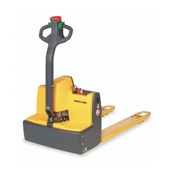
B Description of the truck Application The truck is intended for transporting goods on a level floor. It can pick up pallets that are open to the ground or trolleys. The capacity of the truck can be found on the ca- pacity label Q The EME truck has been designed for light duty, maximum continuous operation should not exceed 2 hours. -
Page 11: Description Of The Assemblies And Functions
Description of the assemblies and functions Item Designation Control shaft Collision protection button Controller Battery charge plug 230 VAC (integrated battery charger, 24 V / 6,5 A) Emergency-off switch/ key switch Battery charge connection 24 VDC (lorry charging) Discharge control LED (discharge indicator) Load lifting device Load-bearing wheel Front hood... -
Page 12: Truck
Truck Construction: EME is a three-wheel truck with steered drive wheel (12) and two load wheels (9). The easy-to-open hood (10) provides good accessiblity to all units. The control elements are located at the control shaft head. Safety features: – The truck chassis protects the feet of the operator and, in case of collisions, the load lying on the pallet. -
Page 13: Technical Data - Standard Version
Technical data - standard version Technical data specified according to VDI 2198. Technical data are subject to alteration and additions. Performance data for standard trucks Designation Rated load capacity 1200 Load centre Travelling speed with / without load 4.2 / 5 km/h Lifting speed with / without load 20 / 30... -
Page 15: Standards
EN standards Continuous sound level: 66 dB(A) according to prEN 12053 as stipulated in ISO 4871 The continuous sound level is a value averaged according to standard regulations, taking the sound pressure level into account when driving, lifting and idling. The sound pressure level is measured at the ear. -
Page 16: Labels
Labels 1200 2645 Xxxx Xxxx Xxxx Xxxxxxx Xxxxxx Xxxxxx Xxxxxx Xxxxxxxx Xxxxxxx Xxxxxx Xxxxxx Xxxxxx Xxxxxx Xxxxxxxxxxxxxx Xxxxxxxxxxxxxxx Xxxxxxx Xxxxxxxxx Xxxxxxxxxxxxxxxxxxx Xxxxxxxxxxxxxxxxxxxx Xxxxxxxxxx Xxxxxxxxxxxxxxxxx Xxxxxxxxxxxxxxxxxxxxx Xxxxxxxxx Xxxxxxxxxxxxxxxxxxxxxxxxx Xxxxxxxxxxxxxxxxxxx Xxxxxxxxx Xxxxxxxxxxxxxxxxxx Xxxxxxxxxxxxxxxxxxxx Xxxxx Xxxxxxxxxxxxxxxxxx Xxxxx Xxxxxxxxxxxxxxxxxx Xxxxx Xxxxxxxxxxxxxxxxxxxxxx Xxxxx Xxxxxxxxxxxxxxxxxx Xxxxxxx Xxxxxxxxxx Xxxxxx Xxxxxxxxx... - Page 17 Truck identification plate Xxxx Xxxxxxx Xxxxxx Xxxxxxxxx Xxxxxx Xxxxxxxxx Xxxxxxxxxxxxxxxxxxx Xxxxxxxxxxxxxxxxxx Xxxxxxxxxx Xxxxxxxxxxxxxxxxx Xxxxxxxxxxxxxxxxxxx Xxxxxxxxx Xxxxxxxxxxxxxxxxxxx xxxxxxxxxx Xxxxxxxxxx Xxxxxxxxxxxxxxxxx xxxxxxxx Xxxxxxx Xxxxxx Xxxxx Xxxxxxxxxxxxxxxx Xxxx Xxxxxxxxxxxxxxxxxx Pos. Designation Pos. Designation Type Drive power in kW Serial No. Customer no. Rated capacity in kg Min./max.
-
Page 18: C Transportation And Commissioning
C Transportation and commissioning Transportation by crane Only use lifting gear of adequate capacity (loading weight = dead weight + battery weight; see truck identification plate). Lifting points (1) are provided or loading the truck by means of crane gear. The lifting points are covered by plastic covers that must be re-inserted after transport. -
Page 19: Moving An Incapacitated Truck (Emergency Operation)
Moving an incapacitated truck (emergency operation) To move the truck by emergency operation, the electromagnetically applied brake must be released. – Losen screws (2). – Remove front wall (3). – Losen fastening screws (4) until the truck can be moved (no braking action). The truck can now be moved. -
Page 20: D Battery-Servicing,Recharging,Replacement
D Battery-Servicing,recharging,replacement Safety regulations governing the handling of lead-acid batteries The truck must be parked and rendered safe before any operations on batteries are undertaken (refer to chapter E). Servicing staff: Recharging, servicing and replacing of batteries must only be per- formed by qualified personnel. -
Page 21: Charging The Battery Using The Integrated Charger
Charging the battery using the integrated charger Charging the battery with 230 VAC The mains cable of the charger is accessible from outside. – Pull the mains plug (1) out of the receptacle (2) on the charger and plug it into a suitable electric outlet (230 V ±10%). -
Page 22: Charging Battery With 24 Vdc (Lorry)
Charging battery with 24 VDC (lorry) – Connect the charger cable (o) with the 24 VDC connection (4). A green flash-light of the LED (3) indicates that the battery charger is connected to the mains and the battery is being charged. –... -
Page 23: Replacing The Batteries
Replacing the batteries – Loosen screws (5), remove front hood (6) and front wall (7). – Loosen the terminal screws and remove the battery cables from the terminals. Place the battery cables in such a manner that they do not get caught on the truck when the battery is pulled out. -
Page 24: Discharge Led (Discharge Indicator)
Discharge LED (discharge indicator) The LED shows the charging condition of the battery. State Colour Indication green Battery charge > 30% flashing green Battery charge 30 - 20% flashing Battery charge < 20% In case of light applications (load < 300 kg), the battery must already be charged if the green LED flashes. -
Page 26: E Operation
E Operation Safety regulations governing the operation of the fork lift truck Driving permission: The fork lift truck must only be operated by persons who have been trained in the operation of trucks, who have demonstrated to the user or his re- presentative their capability of moving and handling loads, and who have expressly been charged by the user or his representative with the operation of the truck. -
Page 27: Description Of The Operating Controls And Indicators
Description of the operating controls and indicators Item Control or indicator Function Collision protection button The truck moves away from the ope- rator. Controller Controls the direction and speed of travel. Button “Lift load lifting device” For lifting the load lifting device. Button “Lower load lifting de- For lowering the load lifting device. -
Page 29: Starting Up The Truck
Starting up the truck The driver must make sure that nobody is within the danger area of the truck before the truck is switch on or operated or before a load is lifted. Checks and operations to be performed before starting daily work –... -
Page 30: Operation Of The Fork Lift Truck
Operation of the fork lift truck Safety regulations applicable when operating the truck Driving lanes and work areas: Only such lanes and routes that are specially alloca- ted for truck traffic must be used. Unauthorized persons must stay away from work areas. -
Page 31: Driving, Steering, Braking
Driving, steering, braking It is not admissible to stay on the vehicle during driving. Emergency stop – Push the emergency-off button (8). All of the electrical functions are switched off. Automatic braking Releasing the control shaft causes automatic braking - the control shaft automatically moves into the upper braking range (B). - Page 32 Manoeuvering When using button “manoeuvering” (6) the driver must be especially careful. The truck can be driven with the control shaft in vertical position (e.g. in narrow loca- tions / elevators): – Push the “manoeuvering” button (6). – Move the drive control (2) into the desired driving direction (F or R).
-
Page 33: Picking Up And Setting Down Loads
Accelerating on slopes The load must face uphill! The slope to be negotiated must not exceed 10 m in length: – without load: – load of 600 kg: – load of 1200 kg: 3,5% The truck must not be drived on slopes exceeding the specified values. Successive slopes may only be negotiated after longer breaks. -
Page 34: Parking The Truck And Rendering It Safe
Parking the truck and rendering it safe Always render the truck safe when parking it. Do not park the truck on slopes. The load lifting device must always be completely lowered. – Lower the load lifting device. – Set the key element (8) to vertical position and remove the key. - Page 35 E 10...
-
Page 36: F Maintenance Of The Fork-Lift Truck
F Maintenance of the fork-lift truck Operational safety and environmental protection The checks and servicing operations contained in this chapter must be performed in accordance with the intervals as indicated in the servicing checklists. Modifications of fork-lift truck assemblies, especially of the safety installations, are not permitted. - Page 37 Work on the electric system: Work on the electric system of the truck must only be performed by personnel specially trained for such operations. Before commencing any work on the electric system, all measures required to prevent electric shocks have to be taken. For battery-operated fork-lift trucks, the truck must also be depowe- red by removing the battery plug.
-
Page 38: Maintenance Checklist
Maintenance checklist To ensure safe operation and a long service life of the truck, the activities listed in the maintenance checklist must be carried out every 6 months. Chassis / Check all load bearing elements for damage superstructure: Check all bolted connections Drive unit: Check the transmission for noises and leakage Wheels:... -
Page 39: Hydraulic Oil Level
Hydraulic oil level Filler plug for hydraulic oil 0,25 l Fuels, coolants and lubricants Handling consumption-type material: Consumption-type material must always be handled properly. Manufacturer’s instructions are to be observed. Improper handling is injurious to health, life and environment. Consumption-type ma- terials must be stored in adequate containers. -
Page 40: Notes Regarding Maintenance
Notes regarding maintenance Preparing the truck for maintenance work All required safety measures must be taken to prevent any accidents in the course of the servicing and maintenance operations. The following preparatory operations must be performed: – Park the truck and render it safe (see chapter E). –... -
Page 41: Checking The Electric Fuses
Checking the electric fuses – Prepare the truck for maintenance work (see section 4.1). – Remove the front hood (see section 4.2). – Check all fuses for the correct rating and, if necessary, replace. + U V W - Item Designation Type of fuse: Power fuse... -
Page 42: Decommissioning The Fork-Lift Truck
Decommissioning the fork-lift truck If the fork-lift truck is to be decommissioned for more than 6 months, it must be parked in a frost-free and dry location and all measures to be taken before, during and follo- wing decommissioning must be performed as detailed below. During decommissioning, the fork-lift truck must be jacked up, ensuring that the wheels are clear of the ground. -
Page 43: Recommissioning The Truck
Carry out a safety check in accordance with national regulations. Junheinrich recom- mends checks in accordance with FEM Guideline 4.004. Jungheinrich has a special safety department with trained personnel to carry out such checks. The truck must be inspected at least annually (refer to national regulations) or after any unusual event by a qualified inspector. -
Page 44: Faul Localisation And Identification
Faul localisation and identification 10.1 Fault localisation Fault Possible cause Remedial action Truck does – Battery is still being – Disconnect 230 V or 24 V connection not move charged – Key switch in vertical – Push key and turn clockwise to the limit position and then pull out –... -
Page 45: Fault Identification (Flash Codes Emitted By The Led On The Control Board)
10.2 Fault identification (flash codes emitted by the LED on the control board) The control board is fitted with an LED (7) for fault identification purposes. The type of fault can be identified by the flash signal. The faults described below must only be eliminated by trained personnel or after-sa- les service technicians. -
Page 46: Circuit Diagram
10.3 Circuit diagram +15V Legend for the circuit diagram Power stage Backward Control Belly switch 10 Move protection Manoeuvering Sensor bearing Lifting 12 Control shaft switch Lowering 13 Retaining brake Lowering valve 14 Setpoint 1 Lift limit switch 15 Setpoint 2 Hydraulic motor contactor 16 Forward F 11... - Page 48 Jungheinrich traction battery Table of contents Jungheinrich traction battery ..........2-6 with positive tubular plates type EPzS and EPzB Type plate Jungheinrich traction battery..........7 Instruction for use ............8-12 Aquamatic/BFS III water refilling system Jungheinrich traction battery Maintenance free traction batteries with positive tubular plates type EPzV ....................13-17...
-
Page 49: Jungheinrich Traction Battery
Jungheinrich traction battery with positive tubular plates type EPzS and EPzB Rating Data 1. Nominal capacity C5: See type plate 2. Nominal voltage: 2,0 V x No of cells 3. Discharge current:: C5/5h 4. Nominal S.G. of electrolyte* Type EPzS:... - Page 50 Ignoring the operation instructions, repair with non-original parts or using additives for the electrolyte will render the warranty void. For batteries in classes I and II the instructions for maintaining the appropriate protection class during operation must be complied with (see relevant certificate). 1.
- Page 51 Battery container lids and the covers of battery compartments must be opened or re- moved. The vent plugs should stay on the cells and remain closed. With the charger switched off connect up the battery, ensuring that the polarity is cor- rect.
- Page 52 3. Maintenance 3.1 Daily Charge the battery after every discharge. Towards the end of charge the electrolyte level should be checked and if necessary topped up to the specified level with purified water. The electrolyte level must not fall below the anti-surge baffle or the top of the separator or the electrolyte „min“...
- Page 53 5. Storage If batteries are taken out of service for a lengthy period they should be stored in the fully charged condition in a dry, frost-free room. To ensure the battery is always ready for use a choice of charging methods can be made: 1.
-
Page 54: 7. Type Plate, Jungheinrich Traction Battery
7. Type plate, Jungheinrich traction battery Baujahr T ype Year of manufacture Serien-Nr. Lieferanten Nr. Serial-Nr. Supplier No. Nennspannung Kapazität Nominal V oltage Capacity Zellenzahl Batteriegewicht min/max Number of Cells Battery mass min/max Hersteller Jungheinrich AG, D-22047 Hamburg, Germany Manufacturer... -
Page 55: Aquamatic/Bfs Iii Water Refilling System
Aquamatic/BFS III water refilling system for Jungheinrich traction battery with EPzS and EPzB cells with tubular positive plates Aquamatic plug arrangement for the Operating Instructions Cell series* Aquamatic plug type (length) EPzS EPzB Frötek (yellow) (black) 2/120 – 10/ 600 2/ 42 –... - Page 56 Diagrammatic view Equipment for the water refilling system 1. Water tank 2. Level switch 3. Discharge point with ball valve 4. Discharge point with sole- noid valve 5. Charger 6. Sealing coupler 7. Closing nipple 8. Ion exchange cartridge with conductance meter and solenoid valve 9.
- Page 57 4. Filling (manual/automatic) The batteries should be filled with battery water as soon as possible before the battery charging comes to an end; this ensures that the refilled water quantity is mixed with the electrolyte. In normal operation it is usually sufficient to fill once a week. 5.
- Page 58 8. Battery hose connections Hose connections for the individual plugs are laid along the existing electric circuit. No changes may be made. 9. Operating temperature The temperature limit for battery operation is set at 55° C. Exceeding this temperature damages the batteries. The battery filling systems may be operated within a tempe- rature range of >...
- Page 59 10.2.1 Clamping ring tool The clamping ring tool is used to push on a clamping ring to increase the contact pres- sure of the hose connection on the plugs' hose couplings and to loosen it again. 10.3 Filter element For safety reasons a filter element (ident no.: 50307282) can be fitted into the batte- ry's main supply pipe for supplying battery water.
-
Page 60: Jungheinrich Traction Battery
Jungheinrich traction batterie Maintenance free Jungheinrich traction batterie with positive tubular plates type EPzV and EPzV-BS Rating Data 1. Nominal capacity C5: See type plate 2. Nominal voltage: 2,0 Volt x No of cells 3. Discharge current: C5/5h 4. Rated temperature: 30°... - Page 61 Ignoring the operation instructions, repair with non-original parts and non authorised interventions will render the warranty void. For batteries in classes I and II the instructions for maintaining the appropriate protection class during operation must be complied with (see relevant certificate). 1.
- Page 62 With the charger switched off connect up the battery, ensuring that the polarity is cor- rect (positive to positive, negative to negative). Now switch on the charger. When charging the temperature of the battery rises by about 15° C, so charging should only begin if the battery temperature is below 35°...
- Page 63 3.2 Weekly Visual inspection after recharging for signs of dirt and mechanical damage. 3.3 Quarterly After the end of the charge and a rest time of 5 h following should be measured and recorded: • the voltages of the battery •...
-
Page 64: 7. Type Plate, Jungheinrich Traction Battery
Batteries with this sign must be recycled. Batteries which are not returned for the recycling process must be disposed of as hazardous waste! We reserve the right make technical modification. 7. Type plate, Jungheinrich traction battery Baujahr T ype Year of manufacture Serien-Nr.
Need help?
Do you have a question about the EME 112 and is the answer not in the manual?
Questions and answers