Jungheinrich EFG 316 Operating Instructions Manual
Hide thumbs
Also See for EFG 316:
- Operating instructions manual (329 pages) ,
- Operating instructions manual (109 pages) ,
- Operating instructions manual (109 pages)
Table of Contents
Advertisement
Quick Links
Advertisement
Table of Contents

Related Manuals for Jungheinrich EFG 316


Summary of Contents for Jungheinrich EFG 316
- Page 1 EFG 316k/ 316/ 318k/ 318/ 320 01.04- Operating instructions 52020399 01.04...
- Page 2 Used to indicate standard equipment. Used to indicate optional equipment. Our trucks are subject to ongoing development. Jungheinrich reserves the right to alter the design, equipment and technical features of the truck. No guarantee of particular features of the truck should therefore be inferred from the present operating instructions.
-
Page 4: Table Of Contents
Table of contents Correct use and application of the truck Truck description Description of application ..............B 1 Description of assemblies and functions .......... B 2 Description of truck ................B 3 Technical data of standard version ..........B 4 Performance data ................ - Page 5 Operation Safety instructions for floor conveyor operation ....... E 1 Description of the operating controls and indicators ......E 2 Dashboard switches ................. E 4 Operating console switches ............. E 4 Information and service indication ............ E 5 Information indication ............... E 5 LED warning indicators ..............
- Page 6 Operating safety and environmental protection ........F 1 Safety regulations applicable to truck maintenance ......F 1 Servicing and inspection ..............F 3 Maintenance check list for EFG 316/318/320 ........F 4 Lubrication plan for EFG 316/318/320 ..........F 7 Consumption type materials ..............F 8 Description of servicing operations ...........F 9...
-
Page 8: A Correct Use And Application Of The Truck
A Correct use and application of the truck The „Guidelines for the Correct Use and Application of Industrial Trucks“ (VDMA) are included in the scope of delivery for this truck. The guidelines are part of these oper- ating instructions and must always be heeded. National regulations are fully applica- ble. -
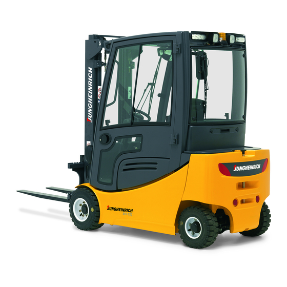
Page 10: B Truck Description
Vehicle types and maximum load capacity. Model max. load capacity*) Load centre EFG 316k 1600 kg 500 mm EFG 316 1600 kg 500 mm EFG 318k 1800 kg 500 mm EFG 318 1800 kg... -
Page 11: Description Of Assemblies And Functions
Description of assemblies and functions Item Designation t Overhead guard t Driver's seat t Counterweight t Batteries t Drive axle t Fork carrier t Hoist frame t Steering system... -
Page 12: Description Of Truck
Description of truck Steering system (8): Low steering forces of 15 N and a good transmission ratio with 5-6 revolutions of the steering wheel enable comfortable and quick steering. The number of wearing parts has been minimised by means of the rack steering offering the advantage of a compact steering unit. -
Page 13: Technical Data Of Standard Version
Technical data of standard version Designation 316k 318k Height with hoist frame retracted 2125 2125 2125 2125 2125 Free lift Length of lift 3300 3300 3300 3300 3300 Height with hoist frame extend- 3850 3850 3885 3885 3885 Height above protective roof 1950 1950 1950... -
Page 15: Performance Data
Performance data Designation 316k 318k Q Load capacity 1600 1600 1800 1800 2000 (at C = 500 mm) *) C Load centre distance Driving speed with / 17 / 17 17 / 17 17 / 17 17 / 17 17 / 17 km/h without load Lifting speed Lifting... -
Page 16: En Standards
EN standards Continuous sound level: 67 dB(A) according to EN 12053 as stipulated in ISO 4871 The continuous sound level is a value averaged according to standard regulations, taking the sound pressure level into account when driving, lifting and idling. The sound pressure level is measured at the ear. -
Page 17: Location Of Instruction Labels And Identification Plates
Location of instruction labels and identification plates Warning and information labels, such as capacity diagrams, attachment points and identification plates, must be readable at all times or be replaced, if necessary. Item Designation Identification plate Label adjustment steering column Label lifting point Capacity plate Label hydraulic function (Multi-Pilot) Label Observe operating instructions... -
Page 18: Truck Identification Plate
Truck identification plate Item Designation Item Designation Type Manufacturer Serial No. Min./max. battery weight in kg Rated capacity in kg Drive power in kW Battery: Voltage V Load centre distance in mm Empty weight without battery in kg Year of manufacture Manufacturer logo Option In the event of queries relating to the truck or spare part orders, please state the serial... -
Page 19: Capacity Label Fork Tines (Basic Device)
Example for determination of maximum load capacity: In case of a load centre D of 600 mm and a maximum lifting height H of 3600 mm the maximum load capacity Q is 1105 kg. Capacity label Fork tines (basic device) The capacity label Fork tines indicates the load capacity Q of the fork tines in kg. -
Page 20: C Transportation And Commissioning
C Transportation and commissioning Transportation by crane Only use lifting equipment with sufficient carrying capacity (loading weight = own weight + battery weight; see identification plate of the truck). – Park the truck and render it safe (refer to chapter E). –... - Page 21 To lash down the fork lift truck with the lifting mast installed use the eyes on the top cross beam of the mast and the trailer coupling pin. Lashing and wedging with the lifting mast installed To transport the fork lift truck without lifting mast perform lashing across the overhead guard front.
-
Page 22: First Commissioning
Approximate centre of gravity First commissioning Commisioning and instruction of the driver must only be carried out by personnel with appropriate training. If several trucks are delivered it must be assured that only load suspension devices, hoist frames and basic trucks with identical series number are assembled. -
Page 23: Moving Of The Truck Without Own Drive
Moving of the truck without own drive If the truck must be put on tow, proceed as follows: – Connect tow-bar or tow to the trailer coupling of the recovery vehicle and to the truck to be recovered. – Remove battery plug (refer to chapter D). –... -
Page 24: D Battery - Servicing, Recharging, Replacing
D Battery - Servicing, recharging, replacing Safety regulations governing the handling of lead-acid batteries Before undertaking any operations on the batteries, park the truck and render it safe (refer to chapter E). Servicing staff: Recharging, servicing and replacing of batteries must only be per- formed by qualified personnel. -
Page 25: Battery Types
The following table shows which standard combinations are possible, similar to DIN 43535, with indication of the capacity: EFG 316k 48 V - 5PzS - Battery 550 Ah EFG 316 48 V - 6PzS - Battery 660 Ah EFG 318k 48 V - 5PzS - Battery 550 Ah... -
Page 26: Opening The Battery Hood With Support System (Optional)
Opening the battery hood with support system (optional) If the truck is equipped with a support system, the battery hood can only be opened when the safety straps are swivelled downwards. – In case of the automatic support system, lock the stop knob (2) and swivel the straps downwards. -
Page 27: Open Battery Hood
Open battery hood Park the truck and render it safe (see chapter E). – Release lock of the steering column (1) push steering column forward and secure it in this position. Pay special attention when locking and unlocking the hood of the control valve. With Multi-Pilot (option): –... -
Page 28: Charging The Battery
Charging the battery – Open the battery hood, (see section 4). The battery and the charger must only be connected or disconnected with the battery charger switched off. The surface of the battery cells must be exposed to provide sufficient ventilation. Met- al objects must not be placed on the battery. -
Page 29: Removing And Installing The Battery
Removing and installing the battery – Open battery hood, (see section 4). – Pull out side door (6,7). Batteries with exposed terminals or connectors must be covered with a rubber mat to prevent short-circuits. When changing the battery with the aid of a lifting gear ensure that the lifting gear is of adequate capacity (the battery weight is indicated on the bat- tery identification plate at the battery trough). -
Page 30: Closing Battery Cover
Closing battery cover With Multi-Pilot (option): – Pull control valve cover forward and simultaneously unlatch it by pressing lever (8). Control valve cover moves back by itself. With Solo-Pilot: – After closing the battery cover, swivel control valve cover to the back until it engages. -
Page 32: Safety Instructions For Floor Conveyor Operation
E Operation Safety instructions for floor conveyor operation Driving permission: The floor conveyor must only be operated by personnel that have been adequately trained and have proved to the persons in charge or their rep- resentatives their ability to handle the truck correctly and who have been explicitly en- trusted with the operation of the truck. -
Page 33: Description Of The Operating Controls And Indicators
Description of the operating controls and indicators Item Operating control or in- Function dicator t Steering of the truck with 6 revolutions of the Steering wheel steering wheel from the left to the right. t Indication of the important drive and lift parame- Information and service indication ters, warnings, information about operation... - Page 34 Truck with Multi Pilot (option) Dual-pedal control (option) Vehicle with Solo Pilot and control levers...
-
Page 35: Dashboard Switches
Dashboard switches Function Anti-collision light switch Switch „360° warning light/parking light“ Switch „Windshield wiper and washing system“ Position 1„Windshield wiper ON“ Position 2 „Windshield washer ON“ Operating console switches Function Override switch „Lift switch-off“ Switch „Creep speed“ Switch „Seat heater“ Switch „Truck lighting“... -
Page 36: Information And Service Indication
Information and service indication On the LCD of the information and service indicator the following data are displayed: Operating data, battery loading status, operating hours and service and diagnostic data. Six LEDs, (24) to (29), are positioned above the indicator for indicating warning messages. -
Page 37: Led Warning Indicators
LED warning indicators Six lit LED warning indicators show the following states: Item Function Lighting switched on (green LED) Parking brake applied (red LED) Driving direction forward (direction of the drive) (green LED) Driving direction backwards (direction of the load) (green LED) Brake fluid level too low (red LED) Direction indicator (green LED) Keyboard assignment... -
Page 38: Plain Text Alarm Messages In The Display
Plain text alarm messages in the display The alarm indication of the vehicle is displayed in the display of this menu. From the „driving programs“ display you can changeover to the alarm indication with the „q“ (33) key. Indication of driving programs The driving behaviour of the truck is changed by selctiing single driving programs. -
Page 39: Display Indicators
Display indicators The display shows operating data and error messages. The following driving param- eters can be set via the user menu. Here, the time between maximum actu- A C C E L E R A T I O N ation of the drive switch and 100% posi- tion control of the electronics is set. -
Page 40: Changing Truck Parameters
Changing truck parameters The truck behaviour is changed by changing the truck parameters. This must be ob- served when bringing the truck into service! Parameters must only be changed when the truck is at standstill and not performing any lifting movements. –... -
Page 41: Commissioning The Truck
Commissioning the truck Before starting or operating the truck, or before lifting any loads, the driver has to make sure that nobody is within the danger area. Checks and actions before routine start-up – Visual inspection for damages of the whole truck (especially tires and load carrying devices). -
Page 42: Adjusting The Steering Column
Adjusting the steering column – Release steering column lock (4) and push or pull steering column to the de- sired position. – Tighten steering column lock again. Provide operatability – Unlock master switch (10). To do this: Push rocker (s) in and pull it upward (r) until you notice that the master switch locks in. -
Page 43: Safety Belt
Safety belt Fasten safety belt before using the industrial truck. The belt protects you from serious injuries! Protect safety belt from dirt (e.g. cover during standstill) and clean it in regular inter- vals. Thaw out and dry frozen belt lock or belt winder to prevent them from freezing up again. - Page 44 Safety belt instructions Before starting the industrial truck, pull belt out of the winder slowly, place it over your thighs tight to your body and close the lock. The belt must not be twisted when fas- tening it! When operating the industrial truck (e.g. driving, lifting, lowering, etc.), the driver must be seated with the back at the backrest.
-
Page 45: Automatic/Mechanical Support System (Optional)
Automatic/Mechanical Support System (optional) Never use the truck without functional support system. Have the support system checked after each accident by authorised specialist per- sonnel. Do not modify the support system. With loaded driver’s seat, the dimension 90 mm between strap (1) and seat must be observed to ensure safe working con- ditions. - Page 46 Operating Instructions for the (Automatic) Support System Before travel starts, the function of the support system must be checked. The stop knob (2) must not be locked. – Sit down – Turn the switch key to "On". After having released the parking brake, both safety straps on the left and right side close and lock automatically.
-
Page 47: Working With The Floor Conveyor
Working with the floor conveyor Safety regulations applicable when operating the truck Driving lanes and work areas: Only such lanes and routes that are specially allo- cated for truck traffic must be used. Unauthorised persons must stay away from work areas. - Page 48 Towing of trailers or other vehicles is only allowed occasionally and on paved, lev- el driveways with a maximum deviation of +/-1% and a maximum speed of 5 km/h. Permanent trailer operation is not permitted. While towing, loads are not allowed on the forks. The maximum trailer load given for the fork lift truck for braked and/or unbraked trail- ers must not be exceeded.
-
Page 49: Driving
Driving During operation in electromagnetic fields beyond the admissible limit values uncon- trolled driving motion can occur. Press EMERGENCY STOP (master switch) immediately, decelerate truck with the service brake and pull the parking brake. Determine the cause of the malfunction and inform the supplier`s service, if neces- sary. - Page 50 After having pulled EMERGENCY STOP and having turned the switch key to the right, the vehicle performs a self-test for about 3-4 seconds (test of PLC control and motors). During that time, no driving motion is possible. If the driving pedal is actuated during that time, the display indicates „motion rest position“.
- Page 51 Backward motion (single-pedal) Make sure that the rear driving area is free from obstacles. – Switch driving direction switch (39) on the Multi Pilot or at the Solo pilot (14) backward (R). – Slowly press accelerator pedal (6) un- til the desired speed is reached. Backward motion (dual-pedal) Make sure that the rear driving area is free from obstacles.
-
Page 52: Steering
Decelerating the truck The braking effect of the truck is mainly dependent on the road surface. This must be taken into account by the driver for his driving behaviour. Decelerate the truck care- fully so that the load does not slip. When driving with trailed loads the resulting longer braking path must be kept in mind. - Page 53 Reverse brake (single-pedal): – Switch driving direction switch (39) or (14) to opposite driving direction while driv- ing. The truck is decelerated generatorically by means of the drive current control system until the truck starts to travel in the opposite direction. Depending on the truck type, the driving direction switch can be located –...
-
Page 54: Operating The Lifting Device And Attachments (Control Lever)
Operating the lifting device and at- tachments (control lever) The control lever must only be operated while the driver is sitting on his seat. The driver must be instructed in the opera- tion of the lifting device and attach- ments! Lifting/lowering fork carrier –... -
Page 55: Operating The Lifting Device And Attachments (Multi Pilot)
Operating the lifting device and at- tachments (Multi Pilot) Within the first 3-4 seconds after switch- ing the vehicle ON (self test phase), lift- ing functions are impossible. The display indicates „lift rest position“. The Multi Pilot must only be operated while the driver is sitting on his seat. - Page 56 Additional Control I (Integrated side shifting device) – Press key (47) on the Multi Pilot to push fork carrier to the left. – Press key (48) on the Multi Pilot to push fork carrier to the right. Additional control II The Multi Pilot can be turned for the op- eration of a hydraulic attachment.
-
Page 57: Picking Up, Transporting And Setting Down Of Loads
Picking up, transporting and setting down of loads Before a load unit is taken up the driver has to make sure, that it is correctly palettised and that the load capacity of the truck is not exceeded. Observe capacity label! Adjusting fork tines The fork tines must be adjusted so that both tines have the same distance to the... - Page 58 – Drive the truck with the fork tines as far as possible below the load unit. The fork tines must be under the load with at least two third of their lengths. – Pull parking brake (3). Lift fork carrier until the load is lying freely on the fork tines.
- Page 59 When moving loads the hoist frame must be inclined backward and the fork tines must be lowered as far as possible. Transporting a load If the load is stacked so high that the view in forward direction is impeded, you have to drive backward.
-
Page 60: Safe Parking Of The Truck
Safe parking of the truck If the truck is left unattended, even for only short periods of time, it must be rendered safe. – Driving the truck on even ground. – Pull parking brake (3). – Lower forks completely and incline hoist frame forward. -
Page 61: Trailer Loads
The driver must make sure not to exceed the maximum permissible trailer load prior to coupling the trailer. Maximum trailer load Dead weight Pulling force Trailer loads Truck (kg) (kg) EFG 316k 2850 12700 8550 EFG 316 3025 12700 9075 EFG 318k 3130 12700 9390 EFG 318 3215 12700 9645 EFG 320... -
Page 62: Temperature Monitoring
Temperature monitoring If one of the temperature switches emits the appropriate signal, the performance of the truck will be reduced in relation to the temperature development: while driving in the low-speed mode, with the hydraulic function „Half lifting speed“ being activated, with the control function „Permanent performance adjustment“... - Page 63 E 32...
-
Page 64: F Maintenance Of The Truck
F Maintenance of the truck Operating safety and environmental protection The checks and servicing operations in this chapter must be performed in accordance with the intervals as indicated in the servicing checklists. Modifications of floor conveyor assemblies, especially of the safety installations, are not permitted. - Page 65 Working on the electric system: Works on the electric system of the truck must only be performed by personnel specially trained for such operations. Before commencing any work on the electric system, all measures required to prevent electric shocks have to be taken. For battery-operated floor conveyors, the truck must also be depowered by removing the battery plug.
-
Page 66: Servicing And Inspection
Servicing and inspection Thorough and expert servicing is one of the most important preconditions for safe op- eration of the floor conveyor. The neglect of regular servicing intervals can lead to a breakdown of the floor conveyor, thus representing a potential hazard to personnel and operation. -
Page 67: Maintenance Check List For Efg 316/318/320
Maintenance check list for EFG 316/318/320 Maintenance intervals = t W M M M Standard 1 6 12 24 Chassis/ 1.1 Check all load bearing elements for damage super- 1.2 Check all bolted connections struct.: 1.3 Check tow bar 1.4 Check overhead guard for damages and proper fixing 1.5 Check safety belt for damages and function... - Page 68 Maintenance intervals = t W M M M Standard 1 6 12 24 Hydraulic 6.1 Check all connections for leakage and damage system: 6.2 Check aeration and deaeration filters at the hydraulic tank 6.3 Check the oil level 6.4 Check hydraulic cylinders for leakage, damage and secu- re attachment 6.5 Check the hose line for correct functioning and damage 6.6 Change filter cartridge (hydraulic oil and deaeration filter)
- Page 69 Maintenance intervals = t W M M M Standard 1 6 12 24 Electr. Check the instrument and indicators for correct system: functioning Check all cables for secure connection and damage Check the cable runs for correct functioning and dama- Check functioning of warning devices and safety circuits Check contactors and replace wearing parts, if necessa- Check the fuses for correct amperage...
-
Page 70: Lubrication Plan For Efg 316/318/320
Lubrication plan for EFG 316/318/320 t - D g - E s - E -b - N Slide faces Filler neck Gear oil Grease nipple Drain plug Gear oil Filler neck Brake fluid Filler neck hydraulic oil Drain plug Hydraulic oil... -
Page 71: Consumption Type Materials
Consumption type materials Handling operating agents: Operating agents must always be used with regard to their proper usage and according to the manufacturer specifications. Improper handling is injurious to health, life, and environment. Consumption type ma- terials must be stored in adequate containers. They might be inflammable and, there- fore, must not come into contact with hot components or open fire. -
Page 72: Description Of Servicing Operations
Description of servicing operations Preparation of the truck for servicing and maintenance operation All required safety measures must be taken to prevent any accidents in the course of the servicing and maintenance operations. The following preparatory operations must be performed: –... -
Page 73: Check Hydraulic Oil Level
Check hydraulic oil level The load lifting device must be completely lowered. – Prepare truck for maintenance and service operations. – Unscrew air cleaner with level plunger (2). – Visual check of hydraulic oil level on the level plunge (3). The reading of the hydraulic oil level must be at the upper mark (4) when the tank is sufficiently filled. -
Page 74: Check The Transmission Oil Level
Check the transmission oil level Gear oil must not run into the ground. To prevent this, put an oilpan underneath the gear box. – Park the truck and render it safe (see chapter E). – Unscrew oil filler screw (5). –... -
Page 75: Checking The Brake Fluid
Checking the brake fluid Brake fluid is poisonous and must only be stored in closed original containers. – Park the truck and render it safe (see chapter E). – Remove floor mats. – Unscrew fixing screw and remove bot- tom plate (8). –... -
Page 76: Checking The Electric Fuses
6.11 Checking the electric fuses – Preparation of the truck for servicing and maintenance operation – Open rear cover – Unscrew cover (11). – Check fuses according to table for correct rating and damage. In order to prevent damage to the electric system, only fuses with the respectively specified ratings must be used. -
Page 77: Recommissioning The Truck
6.12 Recommissioning the truck Recommissioning of the truck following the performance of cleaning or maintenance work is permitted only after the following operations have been performed: – Check the horn for proper functioning. – Check the master switch for correct functioning. –... -
Page 78: Recommissioning The Truck
Recommissioning the truck – Thoroughly clean the fork lift truck. – Lubricate the fork lift truck according to the lubrication chart (refer to chapter F). – Clean the battery. Grease the pole screws using pole grease and reconnect the battery. –... - Page 79 F 16...
Need help?
Do you have a question about the EFG 316 and is the answer not in the manual?
Questions and answers