
Related Manuals for Radware Alteon

Summary of Contents for Radware Alteon
- Page 1 Radware Alteon Installation and Maintenance Guide Software Version 28.1.5.0 Document ID: RDWR-ALOS-V2815_IG0203 March, 2012...
- Page 2 Radware Alteon Installation and Maintenance Guide Document ID: RDWR-ALOS-V2815_IG0203...
-
Page 3: Important Notices
Ce guide d’informations est fourni à nos clients dans le cadre de l’installation et de l’usage des produits de Radware décrits dans ce document et ne pourra être utilisé dans un but autre que celui pour lequel il a été conçu. -
Page 4: Copyright Notices
The OnDemand Switch may use software components licensed under the GNU General Public License Agreement Version 2 (GPL v.2) including LinuxBios and Filo open source projects. The source code of the LinuxBios and Filo is available from Radware upon request. A copy of the license can be viewed at: http://www.gnu.org/licenses/old-licenses/gpl-2.0.html... - Page 5 GNU General Public License Agreement Version 2 (GPL v.2), y compris les projets à source ouverte LinuxBios et Filo. Le code source de LinuxBios et Filo est disponible sur demande auprès de Radware. Une copie de la licence est répertoriée sur: http://www.gnu.org/licenses/old-licenses/gpl-2.0.html Ce code est également placé...
- Page 6 Radware Alteon Installation and Maintenance Guide 3. Le nom de l’université, ainsi que le nom des contributeurs ne seront en aucun cas utilisés pour approuver ou promouvoir un produit dérivé de ce programme sans l’obtention préalable d’une autorisation écrite. Ce produit inclut un logiciel développé par Markus Friedl Ce produit inclut un logiciel développé...
- Page 7 Der OnDemand Switch verwendet möglicherweise Software, die im Rahmen der DNU Allgemeine Öffentliche Lizenzvereinbarung Version 2 (GPL v.2) lizensiert sind, einschließlich LinuxBios und Filo Open Source-Projekte. Der Quellcode von LinuxBios und Filo ist bei Radware auf Anfrage erhältlich. Eine Kopie dieser Lizenz kann eingesehen werden unter: http://www.gnu.org/licenses/old-licenses/gpl-2.0.html...
-
Page 8: Safety Instructions
To reduce the risk of fire and electrical shock, disconnect the device from the power line before removing cover or panels. The following figure shows the caution label that is attached to Radware platforms with dual power supplies. Figure 1: Electrical Shock Hazard Label DUAL-POWER-SUPPLY-SYSTEM SAFETY WARNING IN CHINESE The following figure is the warning for Radware platforms with dual power supplies. - Page 9 Radware Alteon Installation and Maintenance Guide GROUNDING Before connecting this device to the power line, the protective earth terminal screws of this device must be connected to the protective earth in the building installation. LASER This equipment is a Class 1 Laser Product in accordance with IEC60825 - 1: 1993 + A1:1997 + A2:2001 Standard.
- Page 10 Radware Alteon Installation and Maintenance Guide Figure 4: Statement for Class B VCCI-certified Equipment Translation of Statement for Class B VCCI-certified Equipment: This is a Class B product based on the standard of the Voluntary Control Council for Interference by Information Technology Equipment (VCCI).
- Page 11 Radware Alteon Installation and Maintenance Guide INTERCONNECTION OF UNITS Cables for connecting to the unit RS232 and Ethernet Interfaces must be UL certified type DP-1 or DP-2. (Note- when residing in non LPS circuit) OVERCURRENT PROTECTION A readily accessible listed branch-circuit over current protective device rated 15 A must be incorporated in the building wiring for each power input.
- Page 12 Pour réduire les risques d’incendie et de chocs électriques, déconnectez le dispositif du bloc d’alimentation avant de retirer le couvercle ou les panneaux. La figure suivante montre l’étiquette d’avertissement apposée sur les plateformes Radware dotées de plus d’une source d’alimentation électrique.
- Page 13 Radware Alteon Installation and Maintenance Guide Les condensateurs au sein de l’unité risquent d’être chargés même si l’unité a été déconnectée de la source d’alimentation électrique. MISE A LA TERRE Avant de connecter ce dispositif à la ligne électrique, les vis de protection de la borne de terre de cette unité...
- Page 14 Radware Alteon Installation and Maintenance Guide Figure 10: Déclaration pour l’équipement de classe B certifié VCCI Traduction de la Déclaration pour l’équipement de classe B certifié VCCI: Il s’agit d’un produit de classe B, basé sur la norme du Voluntary Control Council for Interference by Information Technology Equipment (VCCI).
- Page 15 Radware Alteon Installation and Maintenance Guide Les câbles de connexion à l’unité RS232 et aux interfaces Ethernet seront certifiés UL, type DP-1 ou DP-2. (Remarque- s’ils ne résident pas dans un circuit LPS) PROTECTION CONTRE LES SURCHARGES. Un circuit de dérivation, facilement accessible, sur le dispositif de protection du courant de 15 A doit être intégré...
- Page 16 Servicepersonal durchgeführt werden. Zur Reduzierung der Feuer- und Stromschlaggefahr muss das Gerät vor der Entfernung der Abdeckung oder der Paneele von der Stromversorgung getrennt werden. Folgende Abbildung zeigt das VORSICHT-Etikett, das auf die Radware-Plattformen mit Doppelspeisung angebracht ist. Figure 13: Warnetikett Stromschlaggefahr...
- Page 17 Radware Alteon Installation and Maintenance Guide SICHERHEITSHINWEIS IN CHINESISCHER SPRACHE FÜR SYSTEME MIT DOPPELSPEISUNG Die folgende Abbildung ist die Warnung für Radware-Plattformen mit Doppelspeisung. Figure 14: Sicherheitshinweis in chinesischer Sprache für Systeme mit Doppelspeisung Übersetzung von Sicherheitshinweis in chinesischer Sprache für Systeme mit Doppelspeisung: Die Einheit verfügt über mehr als eine Stromversorgungsquelle.
- Page 18 Radware Alteon Installation and Maintenance Guide ERKLÄRUNG DER VCCI ZU ELEKTROMAGNETISCHER INTERFERENZ Figure 15: Erklärung zu VCCI-zertifizierten Geräten der Klasse A Übersetzung von Erklärung zu VCCI-zertifizierten Geräten der Klasse Dies ist ein Produkt der Klasse A gemäß den Normen des Voluntary Control Council for Interference by Information Technology Equipment (VCCI).
- Page 19 Radware Alteon Installation and Maintenance Guide Übersetzung von Erklärung zu KCC-zertifizierten Geräten der Klasse Verkäufer oder Nutzer sollten davon Kenntnis nehmen, daß dieses Gerät der Klasse A für industriell elektromagnetische Wellen geeignete Geräten angehört und dass diese Geräte nicht für den heimischen Gebrauch bestimmt sind.
-
Page 20: Document Conventions
Radware Alteon Installation and Maintenance Guide Vorsicht - Zur Reduzierung der Stromschlag- und Feuergefahr 1. Dieses Gerät ist dazu ausgelegt, die Verbindung zwischen der geerdeten Leitung des Gleichstromkreises und dem Erdungsleiter des Gerätes zu ermöglichen. Siehe Montageanleitung. 2. Wartungsarbeiten jeglicher Art dürfen nur von qualifiziertem Servicepersonal ausgeführt werden. -
Page 21: Table Of Contents
Verifying Accessibility of Management Ports ............... Configuring the Management Port ................Configuring the Management Port for Alteon Application Switch 4408 ....... Configuring the Management Port for Alteon Application Switch 4416, 5224, 5224 XL, 5412, and 5412 XL ........................Initial Configuration of the Device ................ - Page 22 5412, or 5412 XL ..................... Replacing a Power Supply on Alteon Application Switch 4408 ........... Replacing a Power Supply on Alteon Application Switch 4416, 5224, 5224 XL, 5412, or 5412 XL ............................Replacing the Compact Flash on Alteon Application Switch 4416, 5224, 5224 XL, 5412, or 5412 XL ..........................
- Page 23 Radware Alteon Installation and Maintenance Guide Table of Contents Transceiver Module Specifications for Alteon Application Switch Platforms ....... Serial Cable Pin Assignment ..................Serial (RS-232) Console Cable Assignments .............. Alteon 4408 Serial Console Cable Assignment ..............Alteon 5224 Serial Console Cable Assignment ..............
- Page 24 Radware Alteon Installation and Maintenance Guide Table of Contents Document ID: RDWR-ALOS-V2815_IG0203...
-
Page 25: Chapter 1 - Preface
Appendix B - Glossary, page 93—Includes a list of terms used in this document. Related Documentation Alteon Application Switches have the following related documentation, which may be required for various tasks described in this book: • Alteon Application Switch Operating System Command Reference •... - Page 26 Radware Alteon Installation and Maintenance Guide Preface • Alteon Application Switch Troubleshooting Guide • Alteon Application Switch Release Notes Document ID: RDWR-ALOS-V2815_IG0203...
-
Page 27: Chapter 2 - Alteon Application Switch Platforms
Alteon Application Switch 4416, page 29 • LCD Module—Alteon Application Switch 4416, page 31 Alteon Application Switch 4408 Figure 1: Alteon Application Switch 4408 Front Panel (Single and Dual Power Supply Models) Table 1: Alteon Application Switch 4408 Front Panel Feature Label/Description Power button. - Page 28 Figure 2: Alteon Application Switch 4408 Back Panel (Single Power Supply Model) Figure 3: Alteon Application Switch 4408 (with Dual Power Supply) Back Panel Table 2: Alteon Application Switch 4408 Back Panel...
-
Page 29: Alteon Application Switch 4416
Radware Alteon Installation and Maintenance Guide Alteon Application Switch Platforms Alteon Application Switch 4416 Figure 4: Alteon Application Switch 4416 Front Panel LCD menu buttons Table 3: Alteon Application Switch 4416 Front Panel Feature Label/Description SFP GbE ports for traffic or management. The platform supports four (4) SFP ports. - Page 30 Red or alternating red and green indicates a warning (for example, the temperature is high, but still in the allowed range). Figure 5: Alteon Application Switch 4416 (with Single Power Supply) Back Panel Figure 6: Alteon Application Switch 4416 (with Dual Power Supply) Back Panel...
-
Page 31: Lcd Module-Alteon Application Switch 4416
Radware Alteon Installation and Maintenance Guide Alteon Application Switch Platforms LCD Module—Alteon Application Switch 4416 Alteon Application Switch 4416 supports an LCD module, which consists of the LCD itself and LCD menu buttons. Note: The Alteon 4408, 5224, 5224 XL, and 10000 models do not have an LCD. - Page 32 Radware Alteon Installation and Maintenance Guide Alteon Application Switch Platforms Table 5: Alteon Application Switch 5224 and 5224 XL Front Panel Feature Label/Description 2 (Two) Gigabit Ethernet (10GbE) ports for traffic or in-band management. The platform supports four XFP ports.
-
Page 33: Alteon Application Switch 5412 And 5412 Xl
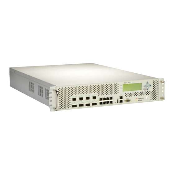
Radware Alteon Installation and Maintenance Guide Alteon Application Switch Platforms Figure 9: Alteon Application Switch 5224 and 5224 XL Back Panel Table 6: Alteon Application Switch 5224 and 5224 XL Back Panel Feature Description Dual power supply sockets The socket to which the power cable is connected. - Page 34 Radware Alteon Installation and Maintenance Guide Alteon Application Switch Platforms Table 7: Alteon Application Switch 5412 and 5412 XL Front Panel Feature Label/Description 10 (Ten) Gigabit Ethernet (10GbE) ports for traffic or in-band management. The platform supports four XFP ports.
-
Page 35: Lcd Module-Alteon Application Switch 5412 And 5412 Xl
For additional technical information, see Appendix A - Specifications, page LCD Module—Alteon Application Switch 5412 and 5412 XL Alteon Application Switch 5412 and 5412 XL platforms support an LCD module, which consists of the LCD itself and LCD menu buttons. Note: The Alteon 4408, 5224, 5224 XL and 10000 models do not have an LCD. -
Page 36: Alteon Va Platform
After the initial configuration, when the device completes booting, the LCD displays the following: oo Radware Alteon IP: 0.0.0.0 Version 28.1.0.0 Alteon VA Platform To install the Alteon VA platform, make sure to meet the following prerequisites: • Fully functioning VMWare infrastructure: — ESX server —... -
Page 37: Chapter 3 - Installing The Platform
Chapter 3 – Installing the Platform This chapter describes how to install the Alteon Application Switch and connect cables to the network ports, the management port, and the console port. This chapter contains the following sections: • Installation of the 4408, 4416, 5224, 5224 XL, 5412, and 5412 XL Platforms, page 37... -
Page 38: Connecting The Cables To The Platform
1. Insert the 8P8C connector of the RJ-45–to–DE-9 adapter cable to the port labeled CONSOLE. Note: Radware supplies a RJ-45–to–DE-9 adapter cable to connect the console port of the platform to a console PC. 2. Insert the DE-9 connector of the RJ-45–to–DE-9 adapter cable to the console PC. - Page 39 Radware Alteon Installation and Maintenance Guide Installing the Platform 4. Connect the traffic-port cables to the 4408 platform, and take into consideration that each port uses a specific CPU core. Therefore, to ensure optimal performance, input traffic and output traffic should not use the same core. the four cores are numbered 0–3. If you are going to use...
- Page 40 Radware Alteon Installation and Maintenance Guide Installing the Platform Document ID: RDWR-ALOS-V2815_IG0203...
-
Page 41: Chapter 4 - Initial Configuration
Initial Configuration of the Device, page 43 Verifying Accessibility of Management Ports Alteon lets you manage your devices via BBI over HTTP/HTTPS and via CLI over Telnet/SSH. Make sure the connectivity between your client station and the device is not blocked by a firewall. -
Page 42: Configuring The Management Port For Alteon Application Switch 4416, 5224, 5224 Xl, 5412, And 5412 Xl
Configuring the Management Port for Alteon Application Switch 4416, 5224, 5224 XL, 5412, and 5412 XL The management port, MNG 1 and MNG 2, are used exclusively to manage the Alteon Application Switch. Although the device can be managed from any network port, the management port saves consuming a port that could otherwise be used for processing data and traffic. -
Page 43: Initial Configuration Of The Device
MNG, however only MNG 1 is operational. MNG 2 is for future use. To configure the management port for the first time 1. Using the serial cable connect the console port of the Alteon Application Switch to the ASCII terminal or computer running terminal emulation. -
Page 44: Connecting To The Device
Establishing an SSH Connection Establishing a Console Connection To establish a console connection 1. Using the serial cable, connect the console port of the Alteon Application Switch to the ASCII terminal or computer running terminal emulation. 2. Do one of the following: —... -
Page 45: Initial Device Connection
Telnet to manage device configuration, SSH ensures that all data sent over the network is encrypted and secure. For more information on how to establish an SSH connection, see the Alteon Application Switch Operating System Command Reference. Initial Device Connection When a connection has been established with the device, the initial screen is displayed. - Page 46 Radware Alteon Installation and Maintenance Guide Initial Configuration Initial Screen for Alteon Application Switch 4416 The following is example text of the initial screen for Alteon Application Switch 4416. System Information at 20:38:58 Sun Apr 18, 1999 Time zone: No timezone configured (GMT offset -8:00)
- Page 47 Radware Alteon Installation and Maintenance Guide Initial Configuration Initial Screen for Alteon Application Switch 5224 The following is example text of the initial screen for Alteon Application Switch 5224. System Information at 20:38:58 Sun Apr 25, 1999 Time zone: No timezone configured (GMT offset -8:00)
-
Page 48: Virtual Application Delivery Infrastructure (Vadi™) Platforms Installation And Configuration
Radware Alteon Installation and Maintenance Guide Initial Configuration Initial Screen for Alteon Application Switch 5412 The following is example text of the initial screen for Alteon Application Switch 5412. System Information at 11:39:49 Mon May 10, 2010 Time zone: No timezone configured (GMT offset -8:00) -
Page 49: Alteon Va For Vmware Installation And Configuration
Radware Alteon Installation and Maintenance Guide Initial Configuration — Alteon VX — This is an ADC hypervisor that enables the use of multiple vADCs on top of dedicated, specialized Alteon ADC hardware. — VMware — The VMware virtual infrastructure enables sharing physical resources of multiple machines across the entire infrastructure including hypervisors, resource management, and provisioning. - Page 50 Radware Alteon Installation and Maintenance Guide Initial Configuration Deploying the OVF Package To deploy the OVF 1. Log into the VMware vSphere client. 2. Deploy the OVF package by selecting File > Deploy OVF Template. The Deployment OVF Template wizard is displayed.
-
Page 51: Alteon Va For Kvm Installation And Configuration
11. Assign each network adapter to the pre-defined network connections for management, clients, and servers, as shown in the following window: Alteon VA for KVM Installation and Configuration To set up Alteon VA for KVM, you must first obtain the KVM package for Alteon VA provided by Radware. Installation Prerequisites A fully functioning KVM infrastructure is required, that includes: •... - Page 52 Radware Alteon Installation and Maintenance Guide Initial Configuration Deploying the Package To deploy the package 1. Unpack the Alteon VA package. For example: # tar -xzvf Alteon-28.1.0.0_VA_kvm.tgz 2. Run the setup script from ./install/bin/rhev_setup 3. Select a location for the new image: remote or local host.
- Page 53 Radware Alteon Installation and Maintenance Guide Initial Configuration 5. At the prompt, enter the root password for the remote host. 6. Confirm the root password for the host. 7. Enter your path to the Export Domain (for example /RHEV/KVM/EXPORT). The KVM deployment process is now initiated.
- Page 54 8. Following the initiation process, you are returned to the Alteon VA deployment screen. 9. Enter q to quit. 10. Go to the RHEV-M management console, expand the System tree, and locate Alteon VA in the EXPORTS data store. It can now be deployed to a host.
- Page 55 Machine(s) window appears with the Alteon VA name. 13. Select the Destination Cluster, (and Destination Storage if not the default) and click OK. The Alteon VA image is imported into the cluster. This may take a few minutes. Note: Radware recommends that you create a template from the imported Alteon VA Virtual Machine and use it to create a working Alteon VA instance.
- Page 56 Before powering up your Alteon VA, ensure that you connect the network interfaces to different networks. 14. Go to Cluster > Virtual Machine and select the Alteon VA Virtual Machine. 15. Select the Network Interfaces tab, as shown below.There are three (3) interfaces connected to the default network as follows: •...
- Page 57 Radware Alteon Installation and Maintenance Guide Initial Configuration • eth1 — traffic • eth2 — traffic 16. If you select the eth1 interface and connect it to the client network, then you need to select the eth2 interface and connect it to the server network. The following figures illustrate this example.
-
Page 58: Alteon Va For Open Xen Installation And Configuration
18. Run the Alteon VA Virtual Machine. Note: If your network has a DHCP server, you will see the Alteon VA IP address. If not, you will need to configure this manually. See the Alteon Application Switch Operating System Command Reference Guide. -
Page 59: Initial Deployment Of Alteon Va
9. Confirm or change the network bridge for data port 1. 10. Confirm or change the network bridge for data port 2. Initial Deployment of Alteon VA After installing the Radware package, you must now deploy the Alteon VA for the appropriate environment. This is set out as follows: •... - Page 60 Alteon VA for all environments 1. To get the management IP address, do one of the following: — In the vSphere interface, click the Summary tab of your defined Alteon VA to view the IP address of the management network. —...
-
Page 61: Obtaining And Installing A Permanent License For Alteon Va
Further configuration of Alteon VA can be performed through one of the management interfaces. Once the license is set and the IP addresses have been configured on the data ports, Alteon VA is able to receive configurations through the data ports. - Page 62 Radware Alteon Installation and Maintenance Guide Initial Configuration Document ID: RDWR-ALOS-V2815_IG0203...
-
Page 63: Chapter 5 - Maintenance And Software Upgrade
Licensing Mechanism, page 66 Note: For more information on licenses, contact Radware Technical Support. Rebooting Devices For general information on rebooting the Alteon devices, see the Alteon Application Switch Operating System Command Reference. This section includes specific rebooting procedures for the following: •... -
Page 64: Managing Device Configuration Files
Alteon Application Switch device. Tip: Save device configurations periodically on the physical platform. For information on managing the device configuration files, see the Alteon Application Switch Operating System Command Reference. Downloading Software Check for version availability with Radware Technical Support before performing the download. -
Page 65: Upgrading The Alteon Application Switch
Web site. You must obtain this password before you load the upgrade file onto the Radware device. If you do not supply the correct password during the upgrade process, you cannot upgrade, the device will abort the upgrade process, and will revert to the installed version of software. -
Page 66: Licensing Mechanism
The license for Alteon Application Switch determines the maximum throughput and the features that the device supports. For information on all the licensing procedures mentioned in this section, see the Alteon Application Switch Operating System Command Reference. Radware Permanent License The Radware permanent license is a string that is associated with an individual device and includes all the supported features (keys). -
Page 67: Licenses For Evaluation-Temporary Licenses
Radware provides temporary licenses for new features that you wish to evaluate after you have upgraded to the new version of Alteon and have installed at least one permanent license. The temporary evaluation licenses last for 30 days, and are disabled after that period if you do not upgrade them to be included in your permanent license. -
Page 68: Checking License Status
>> Alteon issues messages when the current throughput is approaching the limit of the throughput licence. The severity of this message in syslog, for example, is LOG_ALERT. You can configure the threshold at which the device starts sending these messages. The value for the parameter is a percentage of the maximum throughput. -
Page 69: Chapter 6 - Troubleshooting
• Files for Radware Technical Support, page 70 • Recovery for Alteon Application Switches 4408, 4416, 5224, 5224 XL, 5412, and 5412 XL, page 71 Troubleshooting for Alteon Application Switch Platforms The following table describes problems, possible causes, and solutions. -
Page 70: Fan Failure And Cpu Temperature
SNMP trap issued. Files for Radware Technical Support If you open a support call with Radware Technical Support, you may be asked to provide any of the following files for troubleshooting purposes: •... -
Page 71: Alteon Password Recovery
Recovery for Alteon Application Switches 4408, 4416, 5224, 5224 XL, 5412, and 5412 XL You can use the process described in this section to salvage an Alteon Application Switch that failed during system boot.Before starting this procedure, contact Radware Technical Support to validate that this is the only rescue-measure option. - Page 72 10. When successful, the application installation process runs automatically and displays progress information on the console. 11. When the primary installation is completed, remove the USB from the Alteon device. The device will prompt and wait for this confirmation. 12. Press Enter to confirm the USB is out of the Alteon device.
- Page 73 Note: In case of failure, an appropriate message is displayed. 15. Reconfigure the management port (see Initial Configuration, page 41). 16. Restore the previous configuration. For more information, see the Alteon Application Switch Operating System Command Reference. Document ID: RDWR-ALOS-V2815_IG0203...
- Page 74 Radware Alteon Installation and Maintenance Guide Troubleshooting Document ID: RDWR-ALOS-V2815_IG0203...
-
Page 75: Chapter 7 - Hardware-Component Replacement
• Replacing a Power Supply on Alteon Application Switch 4408, page 75 • Replacing a Power Supply on Alteon Application Switch 4416, 5224, 5224 XL, 5412, or 5412 XL, page 76 • Replacing the Compact Flash on Alteon Application Switch 4416, 5224, 5224 XL, 5412, or 5412... - Page 76 7. Connect the power cable to the new power supply. Replacing the Compact Flash on Alteon Application Switch 4416, 5224, 5224 XL, 5412, or 5412 XL You can replace the Compact Flash (CF) on Alteon Application Switches 4416, 5224, 5224 XL, 5412, or 5412 XL. Note: You cannot replace the Compact Flash (CF) on Alteon Application Switch 4408.
-
Page 77: Appendix A - Specifications
Switch platform. The values for some items may differ according to the model of the product, or they may not be applicable for the product. For the availability status of Radware’s Alteon Application Switch NEBS-compliant platforms, contact Radware Technical Support. - Page 78 Radware Alteon Installation and Maintenance Guide Specifications Table 14: General Specifications of Alteon Application Switch 4408 and 4416 Platforms Item Alteon Application Switch 4408 Alteon Application Switch 4416 (and 4416 (and 4408 XL) Hard disk 4 GB default, with enhancement...
- Page 79 Critical: 74º C i – For single power-supply units only. ii – Except for single DC power-supply units. Table 15: General Specifications of Alteon Application Switch 5224 and 5224 XL Platforms Item Alteon Application Switch 5224 Alteon Application Switch 5224 XL...
- Page 80 Radware Alteon Installation and Maintenance Guide Specifications Table 15: General Specifications of Alteon Application Switch 5224 and 5224 XL Platforms Item Alteon Application Switch 5224 Alteon Application Switch 5224 XL SSL CPS 500 CPS scalable up to 2,000 CPS 10,000 CPS scalable up to 32,000 CPS...
- Page 81 Radware Alteon Installation and Maintenance Guide Specifications Table 15: General Specifications of Alteon Application Switch 5224 and 5224 XL Platforms Item Alteon Application Switch 5224 Alteon Application Switch 5224 XL Power 350 W consumption Heat dissipation 1193 BTU/h Certifications Safety: CB, cTUVus, IEC #60950-1...
-
Page 82: Dc Power Supply Connectors For Alteon Application Switches
Use the 12-gauge insulated copper DC-input cables for the connection to each DC power supply. This section contains the following topics: • DC Power Supply Connector for Alteon Application Switch 4408 Single and Dual Power Supply, 4416 Single Power Supply, and 5224 Single and Dual Power Supply Document ID: RDWR-ALOS-V2815_IG0203... - Page 83 For platforms with a dual power supply, there are two connectors, and for platforms with a single power supply there is only one connector. Figure 13: DC Power Supply Connector for Alteon Application Switch 4408 Single and Dual Power Supply, 4416 Single Power Supply, and 5224 Single and Dual Power Supply...
-
Page 84: Power Factors For Alteon Application Switch Platforms
Radware Alteon Installation and Maintenance Guide Specifications DC Power Supply Connector for Alteon Application Switch 4416 Dual Power Supply and Application Switch 5412 Figure 14: DC Power Supply Connector for Alteon Application Switch 4416, and Alteon Application Switch 5412 –48V Blue... - Page 85 Radware Alteon Installation and Maintenance Guide Specifications Table 18: Transceiver-Module Specifications for Alteon Application Swich Platforms Description Manufacturer Manufacturer Part Number 1Gbps Pluggable Copper SFP 1000BASE-T Optech OP6C-TX1-00-C2 Alteon 4416 1Gbps Small Form-Factor Pluggable (SFP) Sanoc SI8512-X5ATO-3C Optics Multimode SX...
-
Page 86: Serial Cable Pin Assignment
The following tables list the pinouts for the serial console port on devices: • Alteon 4408 Serial Console Cable Assignment, page 87 • Alteon 5224 Serial Console Cable Assignment, page 88 • Alteon 4416 and 5412 Serial Console Cable Assignment, page 89 Document ID: RDWR-ALOS-V2815_IG0203... -
Page 87: Alteon 4408 Serial Console Cable Assignment
Radware Alteon Installation and Maintenance Guide Specifications Alteon 4408 Serial Console Cable Assignment Figure 15: RJ-45 to DB9 Serial Console Cable for Alteon 4408 Document ID: RDWR-ALOS-V2815_IG0203... -
Page 88: Alteon 5224 Serial Console Cable Assignment
Radware Alteon Installation and Maintenance Guide Specifications Alteon 5224 Serial Console Cable Assignment Figure 16: RJ-45 to DB9 Serial Console Cable for Alteon 5224 Document ID: RDWR-ALOS-V2815_IG0203... -
Page 89: Alteon 4416 And 5412 Serial Console Cable Assignment
ADC and virtualization services are integrated into an Application Delivery Virtualization Infrastructure. Alteon VA is one of the three ADC form factors offered as part of Radware's VADI architecture, along with a dedicated Alteon device and ADC-VX™ hypervisors as illustrated here. -
Page 90: Layer 2 Features
6 GB to 24 GB. Other memory configurations do not allow you to use ADC-VX. >> Alteon 5224 XL devices require 24 GB of RAM and therefore need an upgrade from 12 GB to 24 GB. The default 12 GB does not support ADC-VX. >>... - Page 91 Radware Alteon Installation and Maintenance Guide Specifications Table 20: Related Specifications Document Title and Source Publication Number IEEE http://standards.ieee.org/catalog/ IEEE Standard for Local Area Networks: Carrier IEEE 802.3 Sense Multiple Access with Collision Detection March 2002 (CSMA/CD) Access Method and Physical Layer Specifications Institute of Electrical and Electronics Engineers, Inc.
- Page 92 Radware Alteon Installation and Maintenance Guide Specifications Document ID: RDWR-ALOS-V2815_IG0203...
-
Page 93: Appendix B - Glossary
Radware Alteon Installation and Maintenance Guide Glossary Appendix B – Glossary The following abbreviations and acronyms are widely used throughout this book. • ARTM — AdvancedTCA Rear Transition Module • ATCA — Advanced Telecommunications Computing Architecture • BBS — Basic Blade Services •... - Page 94 Radware Alteon Installation and Maintenance Guide Glossary • OEM — Original Equipment Manufacturer • OOB — Out-of-band • OS — Operating System • PCI — Peripheral Component Interconnect • PEM — Power Entry Module • PICMG — PCI Industrial Computer Manufacturers Group •...
-
Page 95: Radware Ltd. End User License Agreement
You are provided with to activate the Software, or otherwise, then You may use the Software only for internal evaluation purposes (“Evaluation Use”) for a maximum of 30 days or such other duration as may specified by Radware in writing at its sole Document ID: RDWR-ALOS-V2815_IG0203... - Page 96 Software, or to your relationship with, Radware or any of the Radware Parties (including, without limitation, loss or disclosure of data or information,...
- Page 97 Radware Alteon Installation and Maintenance Guide the possibility of such damages. If any Radware Party is found to be liable to You or to any third- party under any applicable law despite the explicit disclaimers and limitations under these terms, then any liability of such Radware Party, will be limited exclusively to refund of any license or registration or subscription fees paid by you to Radware.
- Page 98 Radware Alteon Installation and Maintenance Guide Document ID: RDWR-ALOS-V2815_IG0203...
Need help?
Do you have a question about the Alteon and is the answer not in the manual?
Questions and answers