Table of Contents
Advertisement
Instruction Manual
Form 1446
June 1994
2502 Series Level-Trol Controller
Contents
. . . . . . . . . . . . . . . . . . . . . . . . . . . . . . .
. . . . . . . . . . . . . . . . . . . . . . . . . . . . .
. . . . . . . . . . . . . . . . . . . . . . . . . . . . . . . . . .
. . . . . . . . . . . . . . . . . . . . . . . . . . . . . . .
. . . . . . . . . . . . . . . . . . . . . . . . . . . . .
. . . . . . . . . . . . . . . . . . . . . . . . . .
. . . . . . . . . . . . . . . . . . . . . . . . . . . . . . . . . . .
. . . . . . . . . . . . . . . . . . . . . . . . . . . .
. . . . . . . . . . . . . . . . . . . . . . . . . . . . . . .
. . . . . . . . . . . . . . . . . . . . . . . . .
. . . . . . . . . . . . . . . . . . . . . . . . . . . . . . .
. . . . . . . . . . . . . . . . . . . . . . . . . . .
. . . . . . . . . . . . . . . . . . . . . . . . . . .
. . . . . . . . . . . . . . . . . . . . . . . . . . . . . . . . . . .
. . . . . . . . . . . . . . . . . . . . . . . . .
. . . . . . . . . . . . . . . . . . . . .
. . . . . . . . . . . . . . . . . . .
. . . . . . . . . . . . . . . . . . . . . . .
. . . . . . . . . . . . . . . . . . . . . . . .
. . . . . . . . . . . . . . . . . . . . . . . .
. . . . . . . . .
. . . . . . . . . . . . . . . . . . . .
. . . . . . . . . . . . . . . . . . . . . . .
. . . . . . . . . . . . . . . . . . . . . .
. . . . . . . . . . . . . .
. . . . . . . . . . . . . . .
. . . . . . . . . . . . . . . . .
. . . . . . . . . . . . . . . . . . . . . .
. . . . . . . . . . . . . . . . . .
. . . . . . . . . . . . . . . . . . . . . . .
2
2
2
2
2
2
4
4
4
5
7
7
7
7
8
8
9
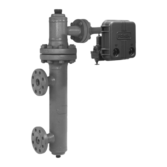
W3121-3/IL
Figure 1. Type 2502 Controller Mounted on
10
10
10
10
10
11
11
11
11
12
13
13
. . . . . . . . . . . . . . . . . . . . . . . . . . . . . . . .
15
. . . . . . . . . . . . . . . . . . . . . . . . . . . . . . . . .
.
15
2502 Series
TYPE 2502 CONTROLLER
TYPE 249B SENSOR
Type 249B Sensor
. . . . . . . . . . . . . . . . . . . . . . . . . . . . .
. . . . . . . . . . . . . . . . . . . . . . . . . . .
. . . . . . . . . . . .
. . . . . . . . . . . . . . . . .
. . . . . . . . . . . . . . .
. . . . . . . . . . . . . . . . . . . .
. . . . . . . . . . . . . . . . . . .
. . . . . . . . . . . . . . . . . . . . . . . . . . . .
. . . . . . . . . . . . . . . . . . . . . . . . .
. . . . . . . . . . . . . . . . . . . . . . . . . . .
. . . . . . . . . . . . . . . . . . . . . . .
. . . . . . . . . . . . . . . . . . . . . . . . . . .
15
16
16
18
19
19
19
20
20
20
20
21
21
21
Advertisement
Table of Contents

Subscribe to Our Youtube Channel
Related Manuals for Fisher 2502 Series Level-Trol


![Controller Fisher] 3660 Instruction Manual](https://static-data2.manualslib.com/product-images/3ac/1225055/60x60/fisher-3660-controller.jpg)


Summary of Contents for Fisher 2502 Series Level-Trol
-
Page 1: Table Of Contents
Form 1446 2502 Series June 1994 2502 Series Level-Trol Controller Contents Introduction ....... -
Page 2: Introduction
If HEAT INSULATOR there are any questions concerning these instructions REQUIRED contact your Fisher Controls sales office or sales rep- resentative before proceeding. NO INSULATOR NECESSARY USE INSULATOR (CAUTION! IF AMBIENT DEWPOINT IS... - Page 3 2502 Series Table 1. Specifications Available Configurations band setting of 0 or 200 percent Maximum: 27 scfh (0.72 m /h) at proportional band Type 2502: A direct-acting controller which pro- setting of 100 percent vides proportional-plus-reset control At 35 psig (2.4 bar) Type 2502C: A Type 2502 with a level indicator Minimum: 7 scfh (0.2 m /h) at proportional band...
-
Page 4: Uncrating
2502 Series ADJUSTING WARNING SCREW LOCKNUT PRESSURE REGULATOR 1/4”-18 NPT When replacing the sensor assembly, SUPPLY CONNECTION the displacer may retain process liquid or pressure. Personal injury or property damage due to sudden release of pres- 1/4”-18 NPT OUTPUT sure, contact with hazardous liquid, fire, FILTER WELL CONNECTION or explosion can be caused by punctur-... -
Page 5: Mounting Cageless Sensors
2502 Series AH9150–A A2613–2/IL A1271–2/IL Figure 4. Cage Head Mounting Positions Figure 5. Cage Connection Styles Note For liquid or interface level applications, it is advanta- geous to install a gauge glass either on the vessel, or If the controller is not mounted on the on the sensor cage (if the cage is tapped for a gauge). - Page 6 2502 Series VENT CENTER OF LIQUID OR EQUALIZING INTERFACE LINE SHUTOFF LEVEL VALVES W0645-1 DRAIN DF5379-A A6771/IL Figure 6. Caged Sensor Mounting MOUNTED CAUTION Since a displacer used in an interface level or a density application must be completely submerged during opera- tion, obtaining desired controller sensi- tivity requires the use of either a thin- wall torque tube or an overweight...
-
Page 7: Side-Mounted Sensor
2502 Series supporting the displacer to prevent it from dropping into the vessel and suf- fering damage. DISPLACER STEM END PIECE To help support a Type 249BP or 249CP displacer, install the displacer stem and stem end piece, or a threaded rod, into the 1/4 inch-28 UNF threaded hole DISPLACER ROD in the displacer spud or stem end piece (figure 8). -
Page 8: Piezometer Ring
Provide a clean, dry, and noncorrosive air or gas on pneumatic equipment, Fisher Con- supply to the controller as follows: trols has no technical basis to recom-... -
Page 9: Prestartup Checks
2502 Series 29A2834-C 30A8943-H A1933/IL RESET ADJUSTMENT W5637/IL/A 21A6447-A A1903/IL 1E8731-C 1E8732-C A1897-1/IL Figure 11. Controller Adjustments Prestartup Checks Adjustment locations are shown in figure 11 unless otherwise indicted. When performing the checks, open loop conditions must exist. One way to obtain an open loop is to ensure that there is no flow through the final WARNING control element. -
Page 10: Adjustments
2502 Series structions in the Calibration section to simulate the gravity of one (water service), and a 90-cubic-inch (1.5 process variable changes required for these checks. L) displacer, move the slide so that 1.0 on scale B is over 90 on scale A. If it is desired to have water level cover 50 per cent of the displacer length at the control Make sure that the raise level dial on the controller is point, read up from 50 on scale D to find a 4.5 dial set-... -
Page 11: Reset Adjustment
2502 Series percentage of pressure fed back to the proportional To calibrate a controller, it is necessary to place the bellows. The adjustment is performed by opening the device into operation. This may be done on the vessel controller cover and turning the percent proportional with the actual service liquid. -
Page 12: Determining Suspended Weight For Calibration
(length of the dis- tions under dry conditions, consult your placer submerged) Fisher Controls sales office or sales rep- resentative for the maximum allowable SP GR = Specific gravity of the lighter liquid at op- substitute weight Ws that can be used erating temperature. -
Page 13: Calibration Procedure
2502 Series Table 2. Minimum and Maximum Limits for Setting Process Variables Application Minimum Limit Maximum Limit Liquid level Displacer must be completely out of liquid Displacer must be completely submerged in liquid Displacer must be completely submerged in the upper Displacer must be completely submerged in the lower Interface of two process liquids... -
Page 14: Principle Of Operation
2502 Series Type 2502 Controller 2. Set the percent proportional band control to 200. 3. Set the reset control to .05 minutes per repeat. As long as inflow and outflow of the vessel are equal, the beam and flapper remain motionless and allow sup- 4. -
Page 15: Type 2502F Controller With Reset Relief Valve
2502 Series CD2114-A CJ4081-A C0313-1 Figure 12. Direct-Acting Right-Hand-Mounted 2502-249 Series Controller Type 2502F Controller with Reset Relief ceeding reset pressure by more than a set value, a feature useful for intermittent control applications. Pro- Valve portional valve output registers in the outer chamber of This construction (figure 13) has a differential relief the relief valve as well as in the proportional bellows. -
Page 16: Maintenance
Maintenance Troubleshooting The 2502 Series controllers are used in combination with 249 Series sensors. Due to the care Fisher Con- When troubleshooting, open loop conditions must exist trols takes in meeting all manufacturing requirements unless otherwise stated. When monitoring the process (heat treating, dimensional tolerances, etc.), use only... -
Page 17: Removing Controller From Sensor
2502 Series Changing Mounting Method Table 3 lists some common operating faults, their probable causes, and corrective action. WARNING To avoid injury from contact with the Removing Controller from Sensor process liquid, lower the vessel level below the torque-tube arm before pro- ceeding. - Page 18 2502 Series Table 3. Troubleshooting Chart for 2502 Series Controllers Fault Possible Cause Check Correction 1. Process wanders or cycles 1.1 Proportional band or specific 1.1 Insure the prestartup 1.1 If stable control cannot be around setpoint. gravity adjsutment incorrect or procedures are completed attained and all other elements are improperly tuned control loop.
- Page 19 2502 Series 20A7423-C/DOC Figure 14. Heat Insulator Shown Installed on 249 Series in the figure. Then mount the insulator assembly (key 35) on the controller case with four washers (key 53) and button-head cap screws (key 40). Tighten the screws. CAUTION In the following step, avoid bending the torque tube rotary shaft of the torque...
-
Page 20: Changing Proportional, Reset, Or Differential Relief Valve
2502 Series 5. Install and tighten the bearing assembly (key 12) in 1. On a controller with indicator assembly, loosen the the case (key1). Secure the operating arm base or point- two lower screws (key 96, figure 17) of the relay case er assembly to the rotary shaft by tightening the hex nut and slide out the indicator base plate (key 53, figure 16). -
Page 21: Disassembling Relay
(key 84), and flapper (key 60). Invert the flapper so that the flapper hook is on the opposite side of the Whenever corresponding with the Fisher Controls beam from the nozzle (key 58), and secure with the sales office or sales representative about this equip- lockwasher and screw. - Page 22 2502 Series 30A8942-H/DOC 30A8943-H/DOC 43A2366-H/DOC Figure 16. 2502 Series Controller Constructions...
- Page 23 2502 Series Description Part Number Description Part Number Retaining Ring, steel, pl (zinc case cover only) (2 req’d) 1A4658 28992 Level Set Pivot Pin, stainless steel 1J4167 35162 Gauge Glass, glass, (2 req’d) 0T0192 06042 Pivot Base, steel, pl 19A9689 X012 Gauge Glass Gasket, neoprene, (2 req’d) 0T0191 04082 Spring Washer, stainless steel...
- Page 24 1N4304 06382 *Recommended spare part. Level-Trol, Fisher, Fisher-Rosemount, and Managing The Process Better are marks owned by Fisher Controls International, Inc. or Fisher-Rosemount Systems, Inc. All other marks are the property of their respective owners. Fisher Controls International, Inc. 1977, 1994; All Rights Reserved...
Need help?
Do you have a question about the 2502 Series Level-Trol and is the answer not in the manual?
Questions and answers