Table of Contents
Advertisement
Instruction Manual
D100325X012
Fisher™ 1061 Pneumatic Piston Rotary Actuator
with Style H & J Mounting Adaptations
Contents
. . . . . . . . . . . . . . . . . . . . . . . . . . . . . . . . .
. . . . . . . . . . . . . . . . . . . . . . . . . . . . .
. . . . . . . . . . . . . . . . . . . . . . . . . . . . . . . . .
. . . . . . . . . . . . . . . . . . . . . . . . . . . . . . .
. . . . . . . . . . . . . . . . . . . . . . . . .
. . . . . . . . . . . . . . . . . . . . . . . . . . . . . . . . . .
. . . . . . . . . . . . . . . . . . . . . . . . . .
. . . . . . . . . . . . . . . . . . . . . . . . . . . . . . . . .
. . . . . . . . . . . . . . . . . . . . . . . .
. . . . . . . . . . . . . . . . . . . . . . . . . . . . . . . .
. . . . . . . . . . . . . . . . . . . . . . . . . . . . . . .
. . . . . . . . . . . . . . . . . . . . . . . . . . . . . . . . . .
. . . . . . . . . . . . . . . . . . . . . . . . . . . .
. . . . . . . . . . . . . . . . . . . . . . . . .
. . . . . . . . . . . . . . . . . . . . . . . . . . . . . . .
. . . . . . . . . . . . . . . . . . . . . . . . . . . . . . . . . .
. . . . . . . . . . . . . . . . . . . . . . . . . . . . . . . . . . .
Introduction
Scope of Manual
This instruction manual includes installation, adjustment, maintenance, and parts ordering information for the Fisher
1061 pneumatic piston rotary actuator (sizes 30, 40, 60, and 68) with H and J mounting adaptations (see figure 1).
Instructions for the positioner, accessories, and, if used, the auxiliary handwheel actuator are covered in separate
instruction manuals.
Do not install, operate, or maintain a 1061 actuator without being fully trained and qualified in valve, actuator, and
accessory installation, operation, and maintenance. To avoid personal injury or property damage, it is important to
carefully read, understand, and follow all the contents of this manual, including all safety cautions and warnings. If you
have any questions about these instructions, contact your
proceeding.
www.Fisher.com
. . . . . . . . . . . . . . . . . . . . . . .
. . . . . . . . . . . . . . . . . .
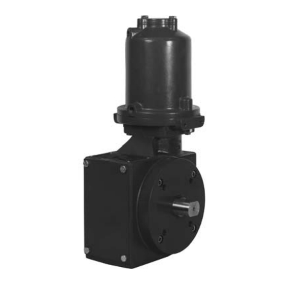
Figure 1. Fisher 1061 Actuator
1
1
2
3
3
3
4
11
11
12
12
13
14
16
16
17
19
19
W4142
19
H Mounting Adaptation
Emerson Process Management sales office
1061 H & J Actuator
January 2016
W4257-1
and Fisher 3610JP Positioner
before
Advertisement
Table of Contents

Related Manuals for Fisher 1061


Summary of Contents for Fisher 1061
-
Page 1: Table Of Contents
This instruction manual includes installation, adjustment, maintenance, and parts ordering information for the Fisher 1061 pneumatic piston rotary actuator (sizes 30, 40, 60, and 68) with H and J mounting adaptations (see figure 1). Instructions for the positioner, accessories, and, if used, the auxiliary handwheel actuator are covered in separate instruction manuals. -
Page 2: Description
1. See separate manual for positioner specifications. Description The 1061 actuator is a pneumatic piston rotary actuator for use with rotary control valves and other equipment. The H mounting adaptation permits the actuator to be used with user‐provided mounting brackets and couplings for rotary actuation of equipment other than Fisher valves. -
Page 3: Specifications
(key 42, figure 6) attached to the actuator. Educational Services For information on available courses for 1061 Style H and J actuators, as well as a variety of other products, contact: Emerson Process Management... -
Page 4: Actuator Mounting
Instruction Manual 1061 H & J Actuator January 2016 D100325X012 Table 3. Acceptable Shaft Diameters and Torque Limits for Actuators with J Mounting COUPLING AVAILABILITY BY KEYED SHAFT DIAMETER TORQUE LIMIT FOR J MOUNTING ACTUATOR SIZE Inches LbfSin 12.7 15.9 1010 19.1... - Page 5 7. If the 1061 actuator is equipped with an auxiliary handwheel actuator, make certain that a cylinder bypass valve (key 68, figure 8) is used to equalize cylinder pressure during handwheel operation. Operating the handwheel actuator by itself against the force of differential cylinder pressures is difficult or even impossible.
- Page 6 Instruction Manual 1061 H & J Actuator January 2016 D100325X012 Figure 2. Fisher 1061 Mounting Dimensions H OR J MOUNTING ACTUATOR SIZE Inches 6.75 14.88 2.12 4.50 6.88 2.88 8.12 16.75 2.50 4.75 7.31 2.88 10.50 16.00 2.50 4.75 7.31 3.00...
- Page 7 Instruction Manual 1061 H & J Actuator D100325X012 January 2016 Figure 2. Fisher 1061 Mounting Dimensions (Continued) J MOUNTING Coupling S (Valve Shaft Actuator Size Inner Diameter) Diameter 9.53 136.7 33.3 15.7 117.3 ‐ ‐ ‐ 11.2 9.58 12.70 12.7 136.7...
- Page 8 Instruction Manual 1061 H & J Actuator January 2016 D100325X012 Figure 2. Fisher 1061 Mounting Dimensions (Continued) H MOUNTING S (Actuator Actuator Size Output Shaft Diameter) 15.75 22.2 26.2 19.1 57.2 28.4 5/16‐18 UNC 15.62 22.10 28.6 26.2 19.1 76.2 38.1...
- Page 9 Instruction Manual 1061 H & J Actuator D100325X012 January 2016 Figure 3. Center of Gravity Dimensions CENTER OF GRAVITY DIMENSIONS ACTUATOR SIZE Inches Inches 2.12 2.50 2.50 2.50 19A1469‐C A3250‐2...
- Page 10 Instruction Manual 1061 H & J Actuator January 2016 D100325X012 Figure 4. Actuator Housing Construction Styles and Mounting Positions DESIRED ACTION OF HOUSING CONSTRUCTION TO SPECIFY Actuator Valve Body or Other Equipment Clockwise to Close Style A Push Down to Open (PDTO)
-
Page 11: Pressure Connections
Perform the steps in the WARNING at the beginning of the Maintenance section. The only adjustment on the 1061 actuator is to make sure that the valve or other operated equipment is correctly closed when the actuator piston is against the travel stop. For accurate adjustment, the valve or other operated equipment must be removed from the pipeline. -
Page 12: Principle Of Operation
CAUTION If using a handwheel actuator, the splines of the 1061 actuator shaft could be damaged if excessive torque is applied to the shaft by the manual actuator while the 1061 actuator is stopped at either end of travel. To protect the shaft, perform the travel stop adjustment procedure found in the separate handwheel actuator instruction manual. -
Page 13: Disassembly
Instruction Manual 1061 H & J Actuator D100325X012 January 2016 D Do not remove the actuator from the valve while the valve is still pressurized. D Always wear protective gloves, clothing, and eyewear when performing any maintenance operations to avoid personal injury. -
Page 14: Assembly
Instruction Manual 1061 H & J Actuator January 2016 D100325X012 mounting plate (key 23) and output shaft (key 94) assembly from the actuator housing (key 21). If necessary, remove the retaining ring (key 95) and separate the output shaft from the mounting plate. For 50.8 mm (2‐inch) output shafts, refer to step 7 for this procedure. - Page 15 Instruction Manual 1061 H & J Actuator D100325X012 January 2016 and secure it to the cylinder assembly with the cap screws (key 6). Tighten all cap screws to the torque value listed in table 7. 5. If the bearing (key 81) was removed, press in the new bearing. The end of the bearing should be flush with the outside of the mounting yoke or mounting plate (key 23).
-
Page 16: Changing Actuator Mounting
Instruction Manual 1061 H & J Actuator January 2016 D100325X012 Then, replace the cover (key 34) and secure it with the cap screws and washers (key 35 and 76). If the holes in the cover and housing do not align, temporarily loosen the cap screws (key 24) and shift the housing slightly. Tighten the cap screws to the torque value listed in table 7. -
Page 17: Changing Positions
Instruction Manual 1061 H & J Actuator D100325X012 January 2016 c. Secure the actuator housing to the mounting yoke with the cap screws (key 24). Tighten the cap screws to the torque value listed in table 7. 6. For an actuator with an H mounting adaptation, a. - Page 18 Instruction Manual 1061 H & J Actuator January 2016 D100325X012 CAUTION Do not use a hammer or similar tool to drive the lever (key 28) off the output shaft. Driving the lever could damage operated equipment. For valves, driving the lever could move the valve disk and bearings away from the centered position causing subsequent damage to valve parts.
-
Page 19: Parts Ordering
Use only genuine Fisher replacement parts. Components that are not supplied by Emerson Process Management should not, under any circumstances, be used in any Fisher valve, because they may void your warranty, might adversely affect the performance of the valve, and could cause personal injury and property damage. - Page 20 Instruction Manual 1061 H & J Actuator January 2016 D100325X012 Description Description 65 Pipe Plug, steel (2 req'd) 36 Travel Indicator Scale, stainless steel (not req'd w/positioner) (not req'd w/handwheel) 66 Pipe Cross, malleable iron (2 req'd) 37 Self Tapping Screw, pl steel ( 2 req'd) 67...
- Page 21 Instruction Manual 1061 H & J Actuator D100325X012 January 2016 Figure 6. Fisher 1061 Actuator with Typical H and J Mounting Adaptations 52A9796‐G STEEL ACCESS PLATE (KEY 72) USED ON ALUMINUM HOUSING CONSTRUCTIONS NOTES: 1. KEYS 4, 5, AND 6 NOT REQUIRED FOR SIZE 60 ACTUATOR.
-
Page 22: J Mounting Adaptation
Instruction Manual 1061 H & J Actuator January 2016 D100325X012 Figure 6. Fisher 1061 Actuator with Typical H and J Mounting Adaptations (Continued) FRONT VIEW DETAIL FOR H MOUNTING 59A2410‐A ADAPTATION NOTES: 1. KEYS 4, 5, AND 6 NOT REQUIRED FOR SIZE 60 ACTUATOR. - Page 23 Instruction Manual 1061 H & J Actuator D100325X012 January 2016 Figure 7. H Mounting for 44.5 or 50.8 mm (1‐3/4 or 2‐Inch) Keyed Equipment Shafts ACTUATOR HOUSING 39A2400‐A A3249 Figure 8. Partial View of Actuator with Bypass Valve BYPASS VALVE 54A5326‐J SHT 2...
-
Page 24: D100325X012 January
Responsibility for proper selection, use, and maintenance of any product remains solely with the purchaser and end user. Fisher and FISHTAIL are marks owned by one of the companies in the Emerson Process Management business unit of Emerson Electric Co. Emerson Process Management, Emerson, and the Emerson logo are trademarks and service marks of Emerson Electric Co.
Need help?
Do you have a question about the 1061 and is the answer not in the manual?
Questions and answers