Table of Contents
Advertisement
Instruction Manual
Form 5084
December 2008
Types 1098-Egr And 1098H-Egr Pressure
Reducing Regulators
!
Failure to follow these instructions or
to properly install and maintain this
equipment could result in an explosion,
fire and/or chemical contamination
causing property damage and personal
injury or death.
Fisher
regulators must be installed,
®
operated, and maintained in accordance
with federal, state, and local codes, rules
and regulations, and Fisher instructions.
if the regulator vents gas or a leak
develops in the system, service to the unit
may be required. Failure to correct trouble
could result in a hazardous condition.
Installation, operation, and maintenance
procedures performed by unqualified
personnel may result in improper
adjustment and unsafe operation. Either
condition may result in equipment
damage or personal injury. Use qualified
personnel when installing, operating,
and maintaining the Types 1098-EGR and
1098H-EGR pressure reducing regulator.
introduction
Scope of Manual
This manual describes and provides instructions
and parts list for Type 1098-EGR or 1098H-EGR
regulator complete with a standard P590 Series
filter and either a 6350 Series regulator, a 61 Series
pilot, or a Type Y600AM Pilot. The Type 1806 relief
valve is also covered when a 61 Series pilot is used.
Instructions and parts lists for monitoring pilots and
other equipment used with this regulator are found in
separate manuals.
Types 1098-EGR and 1098H-EGR
WaRninG
www.emersonprocess.com/regulators
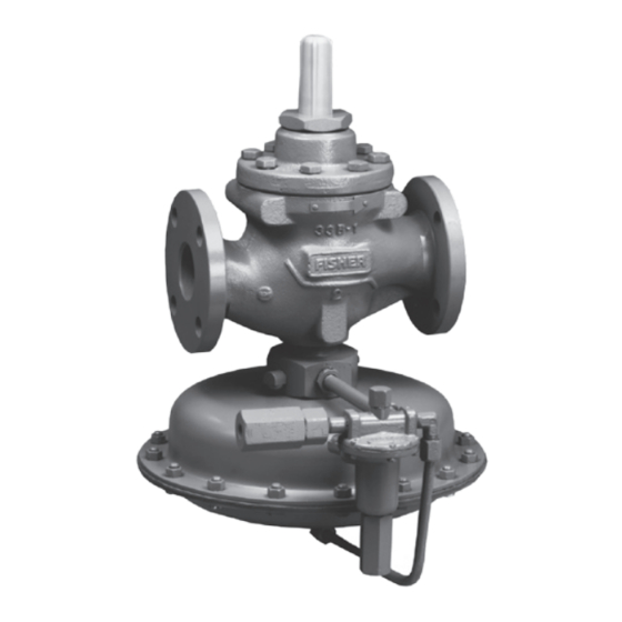
W6956
Figure 1. Type 1098-EGR
Description
Types 1098-EGR and 1098H-EGR regulators provide
economical and accurate pressure control in a
wide variety of applications; natural gas distribution
systems; fuel gas supply to industrial boilers, furnaces,
ovens, and mixers; and large commercial/industrial
establishments such as shopping centers and schools.
They are also used in plant air service and in liquid
service where a slow stroking time (approximately
30 to 90 seconds) is desired on both opening and
closing the main valve.
The Specifications section lists pressure limitations
and other specifications for various Types 1098-EGR
and 1098H-EGR constructions. Specifications for a
given regulator as it originally comes from the factory
are stamped on nameplates located on both the
Advertisement
Table of Contents

Related Manuals for Fisher 1098-EGR


Summary of Contents for Fisher 1098-EGR
- Page 1 30 to 90 seconds) is desired on both opening and closing the main valve. This manual describes and provides instructions and parts list for Type 1098-EGR or 1098H-EGR Specifications regulator complete with a standard P590 Series filter and either a 6350 Series regulator, a 61 Series The Specifications section lists pressure limitations pilot, or a Type Y600AM Pilot.
- Page 2 Types 1098-EGR and 1098H-EGR Specifications Body Sizes and End Connection Styles Main Valve Flow Direction See Table 1 In through the seat ring and out through the cage Main Valve Maximum inlet Pressure Pressure Registration 400 psig (27,6 bar) or body rating limit whichever...
- Page 3 Types 1098-EGR and 1098H-EGR Table 3. Actuator Sizes and Maximum Pressures aCTuaTOR OuTlET (COnTROl) PRESSuRE, PSiG (bar) EMERGEnCy CaSinG PRESSuRE, PSiG (bar) Type Size 100 (6,9) 115 (7,9) 1098 40 (standard) 75 (5,2) 82 (5,7) 50 (3,5) 65 (4,5) 1098H...
- Page 4 Types 1098-EGR and 1098H-EGR TyPE 6351 TyPES 6352, 6353, 6354 6350 SERiES A6563 inlET PRESSuRE OuTlET PRESSuRE aTMOSPHERiC PRESSuRE lOaDinG PRESSuRE TyPE 1806 TyPE 61lD A6641 inlET PRESSuRE OuTlET PRESSuRE aTMOSPHERiC PRESSuRE lOaDinG PRESSuRE Figure 2. Operational Schematics...
- Page 5 Types 1098-EGR and 1098H-EGR 95 SERiES OPTiOnal: TyPE 112 RESTRiCTOR TyPE y600aM M1008 inlET PRESSuRE OuTlET PRESSuRE TyPE y600aM WiTH TyPE 95H SuPPly REGulaTOR aTMOSPHERiC PRESSuRE lOaDinG PRESSuRE PilOT SuPPly PRESSuRE SCREW-On TRaVEl STOP THREaDED SPRinG SEaT W3419–1 DETail OF TyPE 1098H aCTuaTOR W3161–1*...
- Page 6 A mounting assembly for a 40 psi (2,8 bar) differential the pilot restriction code is stamped on the pilot body relief valve is available for the Type 1098-EGR. The (S = standard gain, L = low gain, and H = high gain).
- Page 7 Types 1098-EGR and 1098H-EGR 3. To keep the pilot spring case vent from being elaborate venting systems. This regulator can also be plugged or the spring case from collecting installed in pits subject to flooding by venting the pilot moisture, corrosive chemicals, or other foreign...
- Page 8 The only adjustment necessary on a Type 1098-EGR To adjust the 61 Series or Type y600aM pilots: or 1098H-EGR regulator is the pressure setting of remove the closing cap and turn the adjusting screw.
- Page 9 48A6566-A Figure 4. Typical Dual-Pilot Boiler Fuel Installation B1622 Startup • Type 1098-EGR with Type 6352 pilot • Size 70 Actuator 1. Slowly open the pilot supply line hand valve. • Quick Opening Cage 2. Slowly open the upstream block valve and •...
- Page 10 NPT supply connection in the pipe tee as shown in Figure 4. Do not make the connection in a Supply the boiler pilot light gas with the Type 1098-EGR. turbulent area, such as near a nipple, swage, or The pilot light gas supply line should branch off the elbow.
- Page 11 Types 1098-EGR and 1098H-EGR SaFTEy SHuTOFF ValVE Connect the other end of the control line to the 1/4-inch NPT connection in the control SuPPly pipe tee as shown in Figure 4. Install a hand TO BOilER valve in the control line to shutoff the control pressure when the bypass is in use.
- Page 12 Table 7. The steps operate at a pressure lower than the Type 1098-EGR followed to set the monitoring pilot may vary with or 1098H-EGR working monitor regulator. To do this, each piping situation;...
- Page 13 Types 1098-EGR and 1098H-EGR 16A4296-A 16A4297-A FlExiBlE WiDE-OPEn MOniTOR aRRanGEMEnT THaT PERMiTS MiniMuM PiPinG WiDE-OPEn MOniTOR aRRanGEMEnT THaT WiDE-OPEn MOniTOR TO BE EiTHER uPSTREaM OR DOWnSTREaM REquiRES WiDE-OPEn MOniTOR alWayS TO BE uPSTREaM PilOT SuPPly REGulaTOR Figure 8. Typical Wide-Open Monitor Installations Wide-Open Monitor (Figure 8) 5.
- Page 14 (heat treating, dimensional tolerances, etc.), use only close the hand valve in the control line. replacement parts manufactured or furnished by Fisher. 2. Slowly close the upstream block valve and the The stem O-rings on the Type 1098 or 1098H actuator hand valve in the pilot supply line.
- Page 15 Replacing Quick-Change Trim Package Perform this procedure if the entire trim package is replaced. Key numbers for both the complete Figure 11. Types 1098-EGR and 1098H-EGR Travel main valve and its trim package are referenced in Indicator Assembly Figures 12 and 13. Some replacement trim package assembly numbers are listed in a table in the parts list.
- Page 16 Types 1098-EGR and 1098H-EGR note Replacing Travel Indicator Assembly Access to the spring (key 9), flange The Types 1098-EGR and 1098H-EGR travel indicator O-ring, travel indicator parts, or assemblies now incorporate a redesigned O-ring optional travel stop (key 32) in step 1...
- Page 17 Types 1098-EGR and 1098H-EGR any other surfaces as necessary for ease of shoulder of the fitting, and turn the indicator installation. No further main valve maintenance nut until its flange is aligned with the bottom is necessary if just the indicator fitting and scale marking.
- Page 18 Types 1098-EGR and 1098H-EGR 3. To replace the valve plug (key 4), remove the keep the bellows assembly (key 16) from falling body plug (key 3) to let the valve spring out and possibly getting lost while removing the (key 6) and inner valve assembly (key 4) drop valve plug.
- Page 19 Types 1098-EGR and 1098H-EGR 7. Upon reassembly, pay particular attention to the threads of the replacement orifice with a good following assembly suggestions. grade of light grease and install with 29 to 37 foot-pounds (39 to 50 N•m) of torque.
- Page 20 Types 1098-EGR and 1098H-EGR procedure steps 1 and 4, and pull the stem 2. Inspect the seating surface of the valve plug, (key 14) out of the diaphragm casing (key 4). being sure that the composition surface (or Grease the replacement stem O-ring (key 30,...
- Page 21 Parts Ordering (key 4), remove the upper diaphragm case (key 2), and remove the case O-ring. Each Type 1098-EGR or 1098H-EGR regulator is assigned a serial number or FS number which can be To remove the Types 1098 and 1098H stem found on the nameplates.
- Page 22 Types 1098-EGR and 1098H-EGR Type EGR Main Valve (Figures 12 and 13) Description Part number 400 Psi (27,6 bar) spring color red Description Part number Cast Iron Body Flange 1-inch (DN 25) 25A3170X052 Elastomer Trim Parts kit (included are: 2-inch (DN 50)
- Page 23 Types 1098-EGR and 1098H-EGR Key 1 Type EGR Valve Bodies MaTERial EnD COnnECTiOn 1-inCH (Dn 25) 2-inCH (Dn 50) 34B7611X012 38A8845X012 Cast Iron CL125 FF 34B8630X012 38A8847X012 CL250 RF 37B5950X012 38A8846X012 37B5946X012 38A8848X012 CL150 RF 37B5947X012 38A8853X012 CL300 RF 37B5948X012...
- Page 24 Types 1098-EGR and 1098H-EGR Type EGR Main Valve Description Part number (Figures 12 and 13) (continued) Travel Indicator Stem (continued) 316 stainless steel (NACE) 1-inch (DN 25) (NACE) T14311T0022 Description Part number 2-inch (DN 50) (NACE) T14275T0022 3-inch (DN 80) (NACE)
- Page 25 Types 1098-EGR and 1098H-EGR inDiCaTOR PluG aSSEMBly 35A3167 COMPlETE CaST iROn Full-CaPaCiTy Main ValVE aSSEMBly Figure 12. Type EGR Main Valve Construction...
- Page 26 Types 1098-EGR and 1098H-EGR 26A3800 DETail OF OPTiOnal RESTRiCTED CaPaCiTy COnSTRuCTiOn quiCK-CHanGE TRiM PaCKaGE aSSEMBly 25A3170 Figure 13. Type EGR Main Valve Internal Constructions Type EGR Main Valve (Figures 12 and 13) (continued) Description Part number Description Part number Seat Ring...
- Page 27 Types 1098-EGR and 1098H-EGR Type EGR Main Valve Description Part number (Figures 12 and 13) (continued) Cage O-ring (continued) Ethylenepropylene (EPDM) 1-inch (DN 25) 10A7777X022 Description Part number 2-inch (DN 50) 10A7779X052 Piston Ring 3-inch (DN 80) 14A5688X082 1-inch (DN 25),...
- Page 28 Types 1098-EGR and 1098H-EGR Type EGR Main Valve Types 1098 and 1098H actuators (Figures 12 and 13) (continued) (Figure 14) Description Part number Description Part number Indicator Plug Lower Casing Steel Size 30 1-inch (DN 25) 14A6983X012 Type 1098 2-inch (DN 50)
- Page 29 Types 1098-EGR and 1098H-EGR 56 12 11 10 A6968 34A5692 TyPE 1098 57 12 29 13 11 10 36A8540 TyPE 1098H Figure 14. Types 1098 and 1098H Actuator Assemblies...
- Page 30 Types 1098-EGR and 1098H-EGR A7008 Figure 15. Standard P590 Series Filter Assembly Types 1098 and 1098H actuators (Figure 14) (continued) Description Part number Description Part number Diaphragm (continued) Hex Nut Type 1098 Type 1098H Nitrile (NBR) 2E791902202 Size 30 (12 required)
- Page 31 Types 1098-EGR and 1098H-EGR 34A6635-B CB7988 OlD TyPE 6351 aSSEMBly DRaWinG nEW TyPE 6351 aSSEMBly DRaWinG SHOWinG OlD BODy PluG anD BODy PluG GaSKET SHOWinG nEW BODy PluG anD BODy PluG O-RinG Figure 16. Type 6351 Pilot Assembly Standard P590 Series Filter (Figure 15)
- Page 32 Types 1098-EGR and 1098H-EGR 35A8889 35A6236 DETail OF TyPE 6354M OR 6354H PilOT COMPlETE TyPE 6352, 6353, OR 6354l PilOT Figure 17. Types 6352 through 6354H Pilot Assemblies Type 6351 Pilot (Figure 16) (continued) Description Part number Description Part number...
- Page 33 Types 1098-EGR and 1098H-EGR 20A6328 DETail OF CaPPED aDjuSTinG SCREW OPTiOn 20A6326 30A6327 TyPES 61l, 61lD, anD 61lE PilOT DETail HanDWHEEl OPTiOn Figure 18. Types 61L, 61LD, and 61LE Pilot Assemblies Types 6352, 6353, 6354l, 6354M, and Description Part number...
- Page 34 Types 1098-EGR and 1098H-EGR 30A6330 DETail OF CaPPED aDjuSTinG SCREW OPTiOn 32A2068 TyPE 61H PilOT Figure 19. Type 61H Pilot Assembly 34A0396 Figure 20. Type 61HP Pilot Assembly...
- Page 35 Types 1098-EGR and 1098H-EGR Types 6352, 6353, 6354l, 6354M, and Description Part number 6354H Pilots (Figure 17) (continued) Relay Yoke Types 61L, 61LD, 61LE, and 61H 1D662544012 Type 61HP (2 required) 13A9838X012 Description Part number Closing Cap Assembly Types 61L, 61LD, and 61LE...
- Page 36 Types 1098-EGR and 1098H-EGR A7141_1 Figure 21. Type Y600A Regulator Assembly 61 Series Pilots (Figures 18, 19, and 20) (continued) Description Part number Spring Seat Description Part number Types 61L, 61LD, and 61LE 1B886225072 Type 61H 1D558525072 Upper Relay Diaphragm...
- Page 37 Types 1098-EGR and 1098H-EGR A7144 A7142_1 Figure 22. Type Y600AM Regulator Assembly Figure 23. Diaphragm Casing Cap Screw Location 61 Series Pilots Description Part number (Figures 18, 19, and 20) (continued) Cap Screw (2 required), Plated steel 1C856228992 Spring Case Assembly, Cast iron...
- Page 38 Types 1098-EGR and 1098H-EGR B2666 Figure 24. Type 95H Supply Pressure Regulator Types y600a and y600aM Parts list (Figures 21 through 23) (continued) Description Part number Description Part number Pitot Tube, 304 Stainless steel 17B4479X012 Orifice Machine Screw, Stainless steel...
- Page 39 Types 1098-EGR and 1098H-EGR COnTROl linE COnnECTiOn BOTTOM ViEW OF PilOT (SHOWn ROTaTED 90° FROM nORMal) 14A5706-A Figure 25. Single-Pilot Mounting Assembly Mounting Parts 6350 Series Mounting Parts (Figure 25) Description Part number Description Part number Pipe Tee for use with 50 psig (3,4 bar) relief...
- Page 40 Types 1098-EGR and 1098H-EGR COnTROl linE COnnECTiOn 14A5705 Figure 26. 61 Series Pilot and Type 1806 Relief Valve Mounting Mounting Parts (continued) 61 Series Mounting Parts (Figure 26) Description Part number Description Part number Pipe Nipple Tube Fitting Connector For standard 61 Series mounting...
- Page 41 Types 1098-EGR and 1098H-EGR 37A0565 Figure 27. Working Monitor Assembly...
- Page 42 Types 1098-EGR and 1098H-EGR TyPE 95H SuPPly PRESSuRE REGulaTOR TyPE y600aM PilOT OPTiOnal: TyPE 112 RESTRiCTOR Figure 28. Type 1098-EGR with Type Y600AM Mounting Parts Mounting Parts (continued) Type 1098-EGR with Type Y600AM Mounting Parts (Figure 28) Description Part number Description Part number...
- Page 43 Types 1098-EGR and 1098H-EGR ViEW a-a ViEW B-B SuPPly 6350 SERiES VENT COnTROl 47A7118 TyPE y600aM anD SizE 70 TyPE 1098 COMBinaTiOn SuPPly ViEW a-a ViEW B-B 6350 SERiES COnTROl 47A7118 TyPE 627M anD SizE 70 TyPE 1098 COMBinaTiOn Figure 29. Boiler Fuel Pressure Control Assembly...
- Page 44 For further information visit www.emersonprocess.com/regulators The Emerson logo is a trademark and service mark of Emerson Electric Co. All other marks are the property of their prospective owners. Fisher is a mark owned by Fisher Controls, Inc., a business of Emerson Process Management.
Need help?
Do you have a question about the 1098-EGR and is the answer not in the manual?
Questions and answers