Table of Contents
Advertisement
Instruction Manual
Form 5207
March 1997
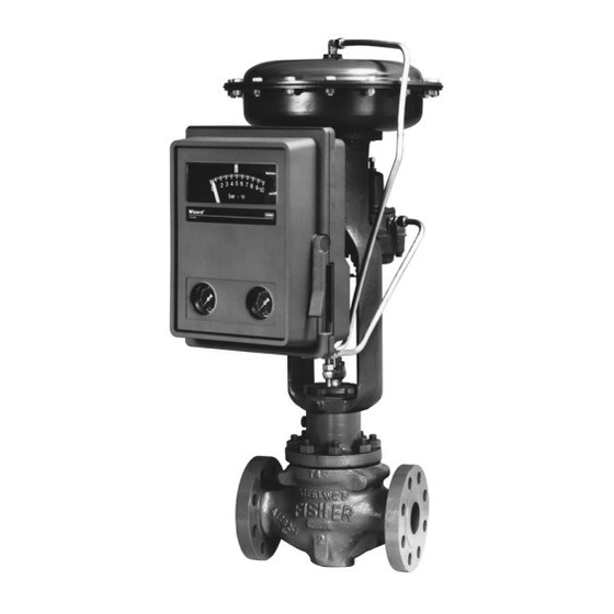
4195KA, KB, and KC Series Gauge Pressure
Controllers
Contents
1. Introduction
. . . . . . . . . . . . . . . . . . . . . . . . . .
Description
. . . . . . . . . . . . . . . . . . . . . . . . . . . . . . .
Specifications
. . . . . . . . . . . . . . . . . . . . . . . . . . . .
. . . . . . . . . . . . . . . . . . . . . . .
. . . . . . . . . . . . . . . . . . . . . . . . . . .
. . . . . . . . . . . . . . . . . . . . . . . . . . . .
. . . . . . . . . . . . . . . . . . . . . . . .
. . . . . . . . . . . . . . . . . . . . . . . . . . . . . . . . . . . . .
. . . . . . . . . . . . . . . . . . . . . . . . . . .
. . . . . . . . . . . . . . . . . . . . . . . .
. . . . . . . . . . . . . . . . . . . . . . . . . . . . .
. . . . . . . . . . . . . . . . . . . . . . . . . . . .
Zero and Span Calibration
. . . . . . . . . . . . . . . . . . . . . . .
Fisher, Fisher-Rosemount, and Managing The Process Better are marks
owned by Fisher Controls International, Inc. or Fisher-Rosemount Systems, Inc.
All other marks are the property of their respective owners.
Fisher Controls International, Inc. 1983, 1997; All Rights Reserved
1-3
1-3
1-3
. . . . . . . . . . . . .
2-1
2-1
2-1
2-1
2-1
. . . . . . . . . . . . . . . . . . . . .
2-1
. . . . . . . . . . . . .
2-1
. . . . . . . . . . . . . .
2-3
. . . . . . . . . . . . . . . . . . .
2-3
. . . . . . . .
2-4
2-4
. . .
3-1
. . . . . . . . . . . . . .
3-1
3-1
. . . .
3-1
. . . . . . . . . . . . . . . .
3-2
3-2
3-2
. . . . . . .
3-3
. . . . .
3-3
. . . . . . . . . . . .
3-3
3-3
. . . . . . . . . . . . . .
3-4
3-6
4195KA, KB, and KC Series
. . . . . . . . . . . . . . . . . . . . . . . . . . . . .
. . . . . . . . . . . . . . . . . . . . . . . .
. . . . . . . . . . . . . . . . . . . . . . . . . . . .
. . . . . . . . . . . . . . . . . . . . . . . . . . . .
. . . . . . . . . . . . . . . . . . . . . . . . . . . . .
. . . . . . . . . . . . . . . . . . . . . . . . . . .
. . . . . . . . . . . . . . . . . . . . . . . .
. . . . . . . . . . . . . . . . . . . . . . . . .
. . . . . . . . . . . . . . . . . . . . . . . . . . .
(suffix letter E)
. . . . . . . . . . . . . . . . . . . . . . . .
. . . . . . . . . . . . . . . . . . . . . . . . . . . . .
. . . . . . . . . . . . . . . . . . . . . . . . . . . . .
. . . . . . . . . . . . . . . . . . . . . . . . . . . .
. . . . . . . . . . . . . . . . . . . . . . . .
. . . . . . . . . . . . . . . . . . . . . . . . . . .
. . . . . . . . . . . . . .
. . . .
. . . . . . . . . . . . . . . .
. . . . . . . . . . . . . . . . . . .
. . . . . . . . . . . .
. . . . . . . . . . . . . .
. . . . . . . . . . . . . . . . . . . . . . .
. . . . . .
. . . . . . . . . . . . . . . . . . .
3-6
3-6
3-7
3-7
4-1
4-1
4-1
4-1
4-2
4-2
4-2
4-2
4-2
4-3
4-3
4-4
4-4
4-4
4-6
4-6
4-8
4-9
4-9
4-11
Advertisement
Table of Contents

Related Manuals for Fisher 4195 KB Series


Summary of Contents for Fisher 4195 KB Series
-
Page 1: Table Of Contents
......4–11 Fisher, Fisher-Rosemount, and Managing The Process Better are marks owned by Fisher Controls International, Inc. or Fisher-Rosemount Systems, Inc. All other marks are the property of their respective owners. Fisher Controls International, Inc. 1983, 1997; All Rights Reserved... - Page 2 4195KA, KB, and KC Series Contents (continued) Replacing Link 2 ..... . . 5–25 Replacing Link 3 ..... . . 5–26 Remote Set Point (suffix letter M) Replacing Link 4...
-
Page 3: Scope Of Manual
Regulator Mounting Parts ....6–9 contact your Fisher Controls sales representative or Regulator Mounting Parts for sales office before proceeding. Casing-Mounted Regulator . - Page 4 10 pounds (4.5 kg) 1. These terms are defined in ISA Standard S51.1-1979. 2. Consult your Fisher sales office or sales representative for additional information. 3. Scfh—Standard cubic feet per hour (60 F and 14.7 psia). Normal m /hr—Normal cubic meters per hour (0 C and 1.01325 bar, absolute).
- Page 5 4195KA, KB, and KC Series Table 1–2. A vailable Configurations for 4195KA, 4195KB, and 4195KC Series Controllers MODES OPTIONS Proportional- Proportional- Proportional- Internal TYPE Plus-Reset- Anti-Reset Remote SERIES Only Plus-Reset Auto/Manual NUMBER Plus-Rate Windup Setpoint (One-Mode (Two-Mode Station (Three-Mode Controllers) Controllers) Controllers) 4195KA...
- Page 6 4195KA, KB, and KC Series Table 1–3. Process Sensor (Capsular Element) Pressure Ratings SPAN OPERATING RANGE CAPSULE CAPSULE CAPSULAR CAPSULAR OPERATING OPERATING MATERIAL STANDARD RANGES LIMIT 0 to 60 inch wc 40 inch wc 60 inch wc –10 inch Hg 5 psig 7.5 psig 0 to 5 psig...
- Page 7 4195KA, KB, and KC Series Table 1–3. Process Sensor (Capsular Element) Pressure Ratings (Continued) SPAN OPERATING RANGE CAPSULE CAPSULE CAPSULAR CAPSULAR OPERATING OPERATING MATERIAL STANDARD RANGES LIMIT 0 to 60 inch wc 40 inch wc 60 inch wc –5 inch Hg 2.5 psig 3.75 psig 0 to 5 psig...
- Page 8 4195KA, KB, and KC Series Table 1–4. Process Sensor (Bourdon T ube) Pressure Ratings and Materials SPAN OPERATING RANGE OPERATING OPERATING BOURDON TUBES BOURDON TUBES STANDARD STANDARD LIMITS Minimum Maximum Minimum Maximum MATERIAL MATERIAL Psig Psig Psig Inch Hg Psig Psig 0 to 30 –30...
-
Page 9: Installation
4195KA, KB, and KC Series Section 2 TYPE 657 ACTUATOR Installation TYPE 4195K CONTROLLER Controller Mounting Orientation Mount the controller with the housing vertical, as shown in figure 2–1, so the vent points down. Pipestand Mounting Refer to figure 2–2. Pipestand mounting parts are pro- vided to mount the controller to a 2-inch (nominal) pipe. - Page 10 4195KA, KB, and KC Series HEX HEAD REGULATOR CAP SCREW (KEY 66) HEX HEAD CAP SCREW LOCKWASHER (KEY 362) (KEY 67) BRACKET HEX NUT (KEY 68) (KEY 364) LOCKWASHER (KEY 363) ELBOW PIPE CLAMP (KEY 365) (KEY 69) HEX HEAD CAP SCREW (KEY 362) PIPE CLAMP...
-
Page 11: Supply Pressure Connection
If the controller has remote set point (suffix letter M), of the problems these influences can connect the remote set point pressure to the top of the have on pneumatic equipment, Fisher controller case at the location shown in figure 2–5. Controls has no technical basis to rec- Use clean, dry air or noncorrosive gas. -
Page 12: External Feedback Pressure Connection (4195Kb Series Controllers Only)
4195KA, KB, and KC Series External Feedback Pressure Connection CAUTION (4195KB Series Controllers Only) When a secondary controller in an override application When installing a remote vent pipe, take has this option, reset windup is minimized in the sec- care not to over-tighten the pipe in the ondary controller. -
Page 13: 5Ka Series Proportional-Only Con- Trollers
4195KA, KB, and KC Series METAL BALL SWITCHING ZONE INDICATOR LOADER KNOB AUTO/MANUAL SWITCH W3679 / IL SET POINT INDICATOR PROCESS POINTER PROPORTIONAL BAND ADJUSTMENT PROPORTIONAL BAND INDICATOR COVER OUTPUT PRESSURE GAUGE W6832 / IL Figure 3–1. 4195KA Series Controller Adjustment Locations Section 3 knob clockwise to increase the process set point and counterclockwise to decrease the process set point. -
Page 14: Changing Controller Action
4195KA, KB, and KC Series Switching The Auto/Manual Station (suffix letter E) CAUTION Switching the controller between auto- matic and manual mode without balanc- ing can disturb the process and cause controller cycling. Refer to figure 3–1 if the controller has the auto/manu- al station (suffix letter E). -
Page 15: Startup For 4195Ka Series Controllers
4195KA, KB, and KC Series 1.0 bar) or 6 to 30 psig (0.4 to 2.1 bar) to the remote 3. Set the proportional band adjustment to 100 per- set point connection at the top of the controller case. cent for fast processes. For slow processes, calculate the proportional band percentage from the equation 3. - Page 16 4195KA, KB, and KC Series Remote Set Point (suffix letter M) Zero Refer to figures 3–1 and 3–3 for adjustment locations. and Span Calibration Refer to figures 3–1 and 3–3 for adjustment locations. Note Refer to figure 5–24 for key number locations. Any change to the process pointer span adjustment will require readjustment of Note...
- Page 17 4195KA, KB, and KC Series POINTER ZERO ADJUSTMENT POINTER ZERO ADJUSTMENT LOCKING SCREW REMOTE SET POINT ZERO ADJUSTMENT (SUFFIX LETTER M) REMOTE SET POINT PROCESS POINTER ZERO ADJUSTMENT SPAN ADJUSTMENT LOCKING SCREW (SUFFIX LETTER M) W6832 / IL SCREW 1 SCREW 2 SCREW 3 39A1126-B...
-
Page 18: Principle Of Operation For 4195Ka Series Controllers
4195KA, KB, and KC Series Flapper Alignment 8. Set the proportional band to 30 percent REVERSE. 9. The controller output should be 9 0.25 psig (0.62 0.02 bar) or 18 0.5 psig (1.2 0.04 bar). If not, ad- Note just flapper leveling screw 1 (the screw nearest the nozzle). -
Page 19: Remote Set Point (Suffix Letter M) Operation
4195KA, KB, and KC Series SET POINT INDICATOR RESET BELLOWS (VENTED) REVERSE ACTION QUADRANT PROPORTIONAL BELLOWS PROPORTIONAL BAND ADJUSTMENT FEEDBACK PROCESS POINTER LINK REMOTE SET POINT CONNECTED HERE FEEDBACK INPUT ELEMENT MOTION FLAPPER PIVOT CONNECTED HERE DIRECT ACTION QUADRANT INPUT CONNECTING MOTION LINK... - Page 20 4195KA, KB, and KC Series MANUAL LOADER AUTOMATIC POSITION AUTO/MANUAL SWITCH MANUAL LOADER KNOB PLASTIC TUBE OUTPUT PRESSURE TO FINAL CONTROL METAL BALL ELEMENT MANUAL RELAY POSITION AUTO/MANUAL SWITCH SUPPLY PRESSURE OUTPUT PRESSURE TO FINAL CONTROL RELAY OUTPUT PRESSURE ELEMENT SUPPLY PRESSURE MANUAL LOADER OUTPUT PRESSURE 48A5230-A...
-
Page 21: 5Kb Series Proportional-Plus-Re- Set Controllers And 4195Kc Series Pro- Portional-Plus-Reset-Plus-Rate Control- Lers
4195KA, KB, and KC Series METAL BALL SWITCHING ZONE INDICATOR LOADER KNOB AUTO/MANUAL SWITCH SET POINT INDICATOR W3679 / IL PROCESS POINTER PROPORTIONAL BAND ADJUSTMENT ANTI-RESET WINDUP DIFFERENTIAL RELIEF VALVE (SUFFIX LETTER F) RATE ADJUSTMENT RESET SUPPLY RESET OUTPUT PRESSURE ADJUSTMENT W3599–1 / IL PRESSURE GAUGE... -
Page 22: Changing Controller Action
4195KA, KB, and KC Series An increasing sensed vacuum decreases output pres- sure. After changing the action, tighten the screws on the proportional band indicator cover. Reset Adjustment To adjust reset, open the controller cover and locate the RESET adjustment. Rotate the adjustment clock- wise to decrease the minutes per repeat or counter- clockwise to increase the minutes per repeat. -
Page 23: Prestartup Checks For 4195Kb And Kc Series Controllers
4195KA, KB, and KC Series To switch from manual to automatic mode, adjust the 8. If necessary, connect a pressure source to the pro- set point to move the ball into the switching zone. Turn cess connection and adjust the process pointer to the the switch to AUTO and adjust the set point to control last mark on the left side of the scale. -
Page 24: Calibration Of 4195Kb And Kc Series Controllers
4195KA, KB, and KC Series Calibration of 4195KB and KC Series Allowable Overshoot P.B. Pressure Span Controllers 2 psig General Calibration Instructions 30 psig 5. If the controller is used in conjunction with a control Note valve, return the control valve to service by slowly opening the upstream and downstream manual control If the controller has the auto/manual sta- valves in the pipeline. - Page 25 4195KA, KB, and KC Series POINTER ZERO ADJUSTMENT POINTER ZERO ADJUSTMENT LOCKING SCREW PROCESS POINTER SPAN ADJUSTMENT ANTI-RESET WINDUP RELIEF VALVE (SUFFIX LETTER F) ANTI-RESET WINDUP VALVE ADJUSTING SCREW (SUFFIX LETTER F) W6833 / IL RESET REMOTE SET POINT REMOTE SET POINT ADJUSTMENT ZERO ADJUSTMENT ZERO ADJUSTMENT...
-
Page 26: Remote Set Point (Suffix Letter M) Zero And Span Calibration
4195KA, KB, and KC Series 5. Apply process pressure equal to the process scale 4. The set point indicator should indicate the process span upper limit. scale lower limit. If not, loosen the remote set point zero adjustment locking screw and adjust the remote 6. - Page 27 4195KA, KB, and KC Series Note 9. Set the proportional band between DIRECT and REVERSE. 4195KB and KC Series controllers with 10. The controller output should be relatively stable at anti-reset windup (suffix letter F) are any value within the output range. If not, adjust flapper supplied with two O-rings (key 52), valve leveling screw 2 (the screw nearest the nozzle) until cover (key 51), and two machine screws...
-
Page 28: Anti-Reset Windup (Suffix Letter F) Differential Relief Valve Calibration
4195KA, KB, and KC Series 3. For a controller with manual set point, move the set point indicator to the mid-scale mark on the process scale. For a controller with remote set point, adjust the remote set point pressure until the set point indicator is at the mid-scale mark on the process scale. -
Page 29: Principle Of Operation For 4195Kb And Kc Series Controllers
4195KA, KB, and KC Series 12. If the differential pressure calculated in step 11 is 8. Turn the reset adjustment to the CLOSED (4195KB incorrect for the application, adjust the differential Series) or OFF (4195KC Series) position. pressure by turning the differential relief valve adjust- 9. - Page 30 4195KA, KB, and KC Series SET POINT RESET BELLOWS INDICATOR REVERSE ACTION QUANDRANT PROPORTIONAL BELLOWS PROPORTIONAL BAND ADJUSTMENT FEEDBACK PROCESS POINTER LINK REMOTE SET POINT CONNECTED HERE FEEDBACK MOTION FLAPPER INPUT ELEMENT PIVOT CONNECTED HERE DIRECT ACTION QUADRANT CONNECTING INPUT MOTION LINK BEAM OUTPUT PRESSURE...
-
Page 31: Anti-Reset Windup (Suffix Letter F) Operation
4195KA, KB, and KC Series SET POINT REVERSE ACTION RESET BELLOWS INDICATOR QUANDRANT PROPORTIONAL BELLOWS PROPORTIONAL BAND ADJUSTMENT FEEDBACK LINK PROCESS POINTER REMOTE SET POINT CONNECTED HERE FEEDBACK FLAPPER MOTION INPUT ELEMENT PIVOT CONNECTED HERE DIRECT ACTION QUADRANT CONNECTING INPUT MOTION LINK BEAM OUTPUT PRESSURE... -
Page 32: External Feedback Operation
4195KA, KB, and KC Series Auto/Manual Station (suffix letter E) RELAY OUTPUT PRESSURE Operation RESET RATE A controller with the auto/manual station (designated VALVE VALVE by the suffix letter E in the type number) has piping on the output side of the relay as shown in figure 4–8. Supply pressure to the relay is also applied to the manual loader. - Page 33 4195KA, KB, and KC Series MANUAL LOADER AUTOMATIC POSITION AUTO/MANUAL SWITCH MANUAL LOADER KNOB PLASTIC TUBE OUTPUT PRESSURE TO FINAL CONTROL METAL BALL ELEMENT MANUAL RELAY POSITION AUTO/MANUAL SWITCH SUPPLY PRESSURE OUTPUT PRESSURE TO FINAL CONTROL RELAY OUTPUT PRESSURE ELEMENT SUPPLY PRESSURE MANUAL LOADER OUTPUT PRESSURE 48A5230-A...
-
Page 34: Maintenance
To prevent the pointer or set point indi- Because of the care Fisher Controls takes in meeting cator from rubbing on the cover or scale all manufacturing requirements (heat treating, dimen-... - Page 35 4195KA, KB, and KC Series Table 5–1. T roubleshooting Chart Fault Possible Cause Check Correction 1. Process wanders or cycles 1.1 If stable control cannot be 1.1 Proportional band and reset 1.1 Refer to the startup procedures about set point settings for controller settings attained, and all other elements of...
- Page 36 4195KA, KB, and KC Series Table 5–1. T roubleshooting Chart (continued) Fault Possible Cause Check Correction 2. Controlling off set point as 2.7 Reset valve leaks 2.7 Hold the input constant and 2.7 Replace the reset valve reflected by process and set point adjust the output to 15 psig (1.0 (4195KB Series) or the rate/reset indicators.
- Page 37 4195KA, KB, and KC Series Table 5–1. T roubleshooting Chart (continued) Fault Possible Cause Check Correction 6. Controller will not attain full 6.5 Nozzle pressure leak 6.5 Check for nozzle tubing leaks 6.5 Tighten the relay nozzle tubing output range with a water bottle and soap nut (key 18).
-
Page 38: Replacing The Relay
4195KA, KB, and KC Series CLEAN-OUT WIRE EXHAUST PORT (NO O-RING USED) O-RINGS W3440 / IL RELAY RELAY MOUNTING SCREWS W5744 / IL Figure 5–2. Relay Construction 4. Install the replacement relay, making sure the tab on the relay, shown in figure 5–2, aligns with the tab on the frame. -
Page 39: Replacing The Gauges
4195KA, KB, and KC Series 7. Remove the blow-out plug (key 72) from the origi- 7. Perform the controller calibration procedures and, if nal case, and install it in the replacement case. necessary, the appropriate remote set point calibration procedure in section 3 or 4. 8. - Page 40 4195KA, KB, and KC Series RELAY NOZZLE TUBING PLASTIC WASHER ASSEMBLY WASHER (KEY 20) (KEY 18) SCREW (KEY 19) E-RING (KEY 27) RETAINING CLIP (KEY 26) O-RING PROPORTIONAL BAND ADJUSTMENT (KEY 25) ADJUSTABLE PLASTIC SET POINT WASHER PIVOT ASSEMBLY (KEY 22) (KEY 17) NOZZLE SET POINT...
- Page 41 4195KA, KB, and KC Series HOLE FLAPPER NOZZLE W3761 / IL W3449 / IL Figure 5–4. Proportional Band Adjustment Knob Setting Figure 5–5. Nozzle-Flapper Positioning 25. Insert the machine screw, with plain washer (keys 19 and 20), through the frame and start it into the relay 19.
- Page 42 4195KA, KB, and KC Series LOCKING ADJUSTABLE SET POINT in section 3 or 4. When calibration is complete, contin- PIVOT ASSEMBLY ue with step 37 below. Note The following procedure (steps 37 through 43) matches the process point- er motion to the set point indicator mo- tion so the controller will control at set point at all positions on the process scale.
-
Page 43: Replacing The Flapper Assembly And Flapper Flexure Pivot Assembly
4195KA, KB, and KC Series PROPORTIONAL BELLOWS BELLOWS BRACKET (KEY 31) ADJUSTABLE SET POINT PIVOT ASSEMBLY (KEY 17) SCREW AND WASHER (KEYS 19 AND 20) LINK 4 LINK 2 W4199 / IL Figure 5–7. Bellows Assembly and Proportional Band Adjustment (Process Scale and Proportional Band Indicator Cover Removed) Slide the controller assembly down to assure an O- 6. - Page 44 4195KA, KB, and KC Series FLAPPER LEVELING FLAPPER LINK 4 LINK 4 ADJUSTMENT SCREW NUMBER 2 ASSEMBLY OBLONG HOLE FLEXURE PIVOT IN FRAME ASSEMBLY SCREWS (KEY 12) W4770 / IL Figure 5–8. Leveling Screw Alignment LINK 2 LINK 3 LINK 2 ADJUSTMENT W3442-1 / IL FLEXURE PIVOT FLAPPER...
- Page 45 4195KA, KB, and KC Series LEVELING SCREW NUMBER 1 CONNECTING TAB ON FLAPPER ASSEMBLY 1/2 OF PIN W4191 / IL DIAMETER W3451 / IL Figure 5–11. Link 2 Adjustment 27. Center the nozzle on the flapper as shown in fig- nozzle capped (to obtain maximum output pressure) ure 5–5 while squeezing the set point beam assembly and check for leaks.
-
Page 46: Replacing The Proportional Or Reset Bellows
4195KA, KB, and KC Series nearest the nozzle) until the output is within 2 psig FOUR SCREWS (KEY 6) (0.14 bar) of supply pressure. 39. Loosen the two adjustment screws on link 4, RESET shown in figure 5–10, and connect the link to the bel- BELLOWS lows bracket (key 31), allowing the link to find its free WASHER... - Page 47 4195KA, KB, and KC Series 7. Remove the four machine screws (key 71) from the does, loosen the four screws (key 6) that attach the bellows beam and remove the bellows beam from the bellows bracket to the bellows beam and reposition frame.
-
Page 48: Replacing The Reset Restriction Valve (4195Kb Series)
4195KA, KB, and KC Series 29. If the reading recorded in step 26 is greater than with anti-reset windup, the relief tubing assembly (key in step 25, adjust the reset gain screw (key 34) one- 44). Tighten all connections. half turn in (clockwise). If the reading recorded in step 8. -
Page 49: Replacing The Anti-Reset Windup (Suffix Letter F) Differential Relief Valve
4195KA, KB, and KC Series 11. Position the gasket (key 5) on the rate/reset valve desired, refer to the anti-reset windup valve calibration assembly. Hold the gasket in place while installing the procedure in section 4. rate tubing assembly (key 137) on the valve assembly using the two machine screws (key 71). -
Page 50: Replacing Bourdon Tube Controller Links
4195KA, KB, and KC Series 9. Perform the controller calibration procedures and, if LINK 4 ADJUSTMENT COURSE ZERO ADJUSTMENT necessary, the appropriate remote set point calibration LINK 1 LINK 4 procedure in section 3 or 4. Replacing Bourdon Tube Controller Links This section describes the separate replacement of four links in the controller. - Page 51 4195KA, KB, and KC Series ALIGNED ZERO ADJUSTMENT MISALIGNED FINE ZERO W3443-1 / IL LOCKING SCREW ADJUSTMENT W3475-1 / IL Figure 5–15. Process Pointer Alignment 7. Perform the controller calibration procedures and, if 7. Adjust the length of link 2 (by turning the adjusting necessary, the appropriate remote set point calibration screw clockwise to increase the length or counter- procedure in section 3 or 4.
- Page 52 4195KA, KB, and KC Series CLINCH FLAPPER LEVELING LINK 4 ADJUSTMENT BELLOWS BRACKET SCREW SCREW HEADS (KEY 31) W4195 / IL Figure 5–17. Position of Link 4 Adjustment Screws W4191-1 / IL Figure 5–16. Flapper leveling Screw and Clinch Nut 3.
-
Page 53: Bourdon Tube Travel Stop Installation And Adjustment
4195KA, KB, and KC Series 11. For a controller with reset, adjust the reset adjust- LOWER TRAVEL STOP ADJUSTMENT LOCK NUT ment to 0.01 minutes per repeat. The rate adjustment MOUNTING SCREW (4195KC) should remain in the OFF position. (KEY 76) 12. -
Page 54: Bourdon Tube Controller Calibration: Zero And Span Adjustment
4195KA, KB, and KC Series Bourdon Tube Controller Calibration: 8. The process pointer should indicate mid-scale 3 percent of the process scale span. If not, loosen the Zero and Span Adjustment screws in link 1 and adjust the length so that the pro- cess pointer points to the mid-scale mark on the pro- cess scale. - Page 55 4195KA, KB, and KC Series POINTER ZERO ADJUSTMENT POINTER ZERO ADJUSTMENT LOCKING SCREW PROCESS POINTER SPAN ADJUSTMENT ANTI-RESET WINDUP RELIEF VALVE ANTI-RESET WINDUP VALVE ADJUSTING SCREW RATE ADJUSTMENT RESET REMOTE SET POINT REMOTE SET POINT RESET ADJUSTMENT W3599-1 / IL ZERO ADJUSTMENT ZERO ADJUSTMENT ADJUSTMENT...
-
Page 56: Capsular Element Controller Maintenance And Calibration
4195KA, KB, and KC Series tube mounting screws (key 384, figure 5–25). Also, 6. Position the replacement capsular element assem- loosen the two screws (keys 379 and 380, figure 5–25) bly over the mounting screw holes. Install and tighten holding the process tubing retainer. the mounting screws (key 127 in figure 5–26). -
Page 57: Replacing The Short Pivot Assembly
4195KA, KB, and KC Series 4. Set the linearity adjustment screw in the replace- BEARING END BUSHING ment pivot assembly to approximately the same loca- tion as noted in step 2. ADJUSTMENT ARM 5. Position the replacement short pivot clevis assem- bly on the mounting plate, and attach it with the two machine screws. -
Page 58: Replacing Capsular Element Controller Links
4195KA, KB, and KC Series 2. Note the hole position of link 1 and disconnect the LINK 5 LINK 1 LINK 4 LINK 4 ADJUSTMENT link from the short pivot clevis assembly and from the process pointer. Remove the link. 3. - Page 59 4195KA, KB, and KC Series process pointer to the process scale upper limit and 12. Repeat steps 8 through 11 until leveling screws 1 tape the process pointer in this position. and 3 protrude an equal distance from the clinch nuts. 13.
-
Page 60: Capsular Element Controller Maintenance Calibration
4195KA, KB, and KC Series 14. Perform the controller calibration procedures and, TRAVEL if necessary, the appropriate remote set point calibra- STOP tion procedure in section 3 or 4. Replacing Capsular Element Controller Link 5 1. Remove the two screws (key 6), and lift off the pro- portional band indicator cover (key 36). - Page 61 4195KA, KB, and KC Series 5. Tighten the machine screw (key 98) and the set make sure the travel stop nut is not contacting the screw in the hex nut to fasten the drive bracket as- travel stop (key 83). sembly in that position.
-
Page 62: Capsular Element Controller Zero And Span Adjustment
4195KA, KB, and KC Series Capsular Element Controller Zero and Span that the process pointer points to the mid-scale mark Adjustment on the process scale. Tighten the screw. 9. Apply process pressure equal to the process scale lower limit. Note 10. -
Page 63: Remote Set Point (Suffix Letter M) Maintenance
4195KA, KB, and KC Series both ends of link 5, move the link down one set of Note holes, and return to step 6. Remove the supply pressure gauge be- fore attempting to remove the capsular element assembly. b. If the span is long (process pointer indication is greater than the process scale upper limit), discon- 1. - Page 64 4195KA, KB, and KC Series GUIDE MOUNTING FLEXURE SCREW DRIVE FLEXURE ADJUSTMENT LINK A SCREW LOWER TRAVEL STOP PIVOT ASSEMBLY A UPPER TRAVEL LINK B STOP LINEARITY ADJUSTMENT PIVOT ASSEMBLY B MOUNTING SCREW TIE BAR CAPSULES REMOTE SET POINT ZERO ADJUSTMENT SCREW ZERO ADJUSTMENT LOCKING SCREW 36A9751-C B1668-4 / IL...
-
Page 65: Replacing Pivot Assembly B (Key 115)
4195KA, KB, and KC Series ther bearing. Tighten the drive flexure screws to hold and do not rest against the end of either pivot assembly A in this position. Do not bend or twist bearing. the flexure when tightening the screws. 3. -
Page 66: Remote Set Point (Suffix Letter M) Maintenance Calibration
4195KA, KB, and KC Series 2. Loosen the screw in the replacement link B and c. Tighten the screw (key 118) on the adjustment adjust the length to match the link being replaced. arm. Tighten the screw. 3. Refer to figure 5–23 for the correct link orientation. Note Attach the replacement link B to the pivot arm and to See figure 5–20. -
Page 67: Remote Set Point Zero And Span Adjustment
4195KA, KB, and KC Series 3. Set the length of link A (key 116) so the lever arms b. To decrease the span further than the adjust- of pivot assembly A and pivot assembly B are parallel ment screw allows, move both ends of link A (key and link A is perpendicular to them. -
Page 68: Auto/Manual Station (Suffix Letter E) Maintenance
4195KA, KB, and KC Series mote set point zero and span adjustment procedure to (key 138) with the two screws (keys 314 and 315). Do correct a span error. not tighten any screws. 6. Repeat steps 1 through 4 until lower, middle, and upper indications are within 1 percent of the process CAUTION scale markings. -
Page 69: Replacing The Loader Range Spring, Diaphragm Assembly, Ball Seat, Tubing, And Ball
4195KA, KB, and KC Series 5. Remove the tubing assembly (key 309). 17. Compress the switch body springs with the loader assembly (key 282), and bolt the switch body assem- bly (key 291) to the loader assembly with the two CAUTION screws (key 290). -
Page 70: Replacing The Loader Valve Plug And Valve Plug Spring
4195KA, KB, and KC Series Replacing the Loader Valve Plug and 7. Position the range spring cup (key 284), range spring (key 283), and the diaphragm assembly (key Valve Plug Spring 281) on the upper loader assembly (key 282). Refer to figure 5–31 for key number location. 8. - Page 71 4195KA, KB, and KC Series SEE VIEW L SEE VIEW H SEE VIEW G SEE VIEW M SEE VIEW E APPLY LUB/ SEALANT 56A9752-U SHT 1 / DOC Figure 5–24. Controller Assembly Drawings 5–38...
- Page 72 4195KA, KB, and KC Series 56A9752-U SHT 4 / DOC 56A9752-U SHT 2 / DOC Figure 5-24. Controller Assembly Drawings (cont’d) 5–39...
- Page 73 4195KA, KB, and KC Series 56A9752-U SHT 3 / DOC Figure 5-24. Controller Assembly Drawings (cont’d) 5–40...
- Page 74 4195KA, KB, and KC Series 56A9752-U SHT 2 / DOC 56A9752-U SHT 3 / DOC 56A9752-U SHT 4 / DOC Figure 5-24. Controller Assembly Drawings (cont’d) 5–41...
- Page 75 4195KA, KB, and KC Series 56A9752-U SHT 4 / DOC 56A9752-U SHT 5 / DOC 56A9752-U SHT 3 / DOC Figure 5-24. Controller Assembly Drawings (cont’d) 5–42...
- Page 76 4195KA, KB, and KC Series 32B1532-A / DOC Figure 5–25. Process and Set Point Indicator Assembly for Bourdon Tube Controllers 5–43...
- Page 77 4195KA, KB, and KC Series 36A6986-C / DOC Figure 5–26. Process and Set Point Indicator Assembly for Capsular Element Controllers (Positive and Compound Pressure Shown) 5–44...
- Page 78 4195KA, KB, and KC Series 39A1126-H / DOC Figure 5–27. Indicator Assembly 5–45...
- Page 79 4195KA, KB, and KC Series VIEW A-A VIEW A-A VIEW A-A VIEW A-A 58A0708-E/DOC 58A0710-C / DOC Figure 5–28. Capsular Element Assembly 5–46...
- Page 80 4195KA, KB, and KC Series APPLY LUB 32B0257-A / DOC Figure 5–29. Type 83U Relay APPLY LUB / SEALANT 36A6988-C / DOC Figure 5–30. Remote Set Point Assembly 5–47...
- Page 81 4195KA, KB, and KC Series APPLY LUB / SEALANT 48A2905-A / DOC Figure 5–31. Auto/Manual Station Assembly 5–48...
- Page 82 4195KA, KB, and KC Series APPLY LUB / ADHESIVE 56A9752-U SHT 5 / DOC Figure 5–32. Internal and External Set Point Assembly 5–49...
-
Page 83: Parts
Parts Ordering Figure 5–24 shows key numbers for the common construction of all controller Whenever corresponding with your Fisher Controls types. Figure 5–24 continues over sever- sales office or representative about this equipment, al pages. Be sure to check all pages of always mention the controller serial number. - Page 84 4195KA, KB, and KC Series Description Part Number Key 46* Pressure Gauge Nozzle ass’y, SST 26A6904 X012 GAUGE MATERIAL Washer, plastic (2 req’d) 16A9767 X012 RANGE RANGE Brass Set pt beam ass’y, aluminum/SST 16A6939 X012 Dual Scale Gauge O–ring, nitrile 0 to 30 psig/ 11B8577 X042 11B8583 X032...
- Page 85 4195KA, KB, and KC Series Key 56 Process and Set Point Indicator Assembly with Bourdon T ube PSIG RANGE PSIG RANGE BAR RANGE BAR RANGE ASSEMBLY PART NUMBER W/O Remote Set Point W/Remote Set Point With S31600 (316 SST) Bourdon Tube 0 to 30 0 to 1.6 or 0 to 2 32B1532 X012...
- Page 86 4195KA, KB, and KC Series Description Part Number Key 61. Process Scale, Positive Pressure Hex reducing nipple, 1/2–inch NPT male Scale Range Part Number (Use only when specified) 0 to 60 inch wc 1R0003 X0202 All ranges up to 0-5000 psig (0-345 bar) 0 to 5 1R0003 X0212 Steel...
-
Page 87: Process And Set Point Indicator Assembly
4195KA, KB, and KC Series Description Part Number Key 61. Process Scale, V acuum and Compound Pressure Zink-Plate No. 770 Sealant SCALE RANGE PART NUMBER (not furnished with controller) Vacuum Pressure 312* O–ring, nitrile For all types w/suffix letter E, Inches Hg 5 to 0 1R0003 X0322... -
Page 88: Indicator Assembly
58A0708 X222 1. For information on scale compatibility, consult your Fisher sales office or sales representative. Capsular Element Assembly may be ordered as part of the Process/Setpoint Indicator Assembly (key 56) or ordered separately. See Capsular Element Assembly section for available replacement parts. -
Page 89: Capsular Element Assembly
4195KA, KB, and KC Series Description Part Number Description Part Number Dial Bracket, G10080 (steel) 36A7050 X012 Inner valve, S30300 (303 SST) 1U9016 35032 Dial bracket, G10080 (steel) 36A7051 X012 Diaphragm ass’y, nitrile/aluminum/SST 1U9018 000A2 Screw, self–tapping, S18800 (18–8 SST) Diaphragm, nitrile 1V5578 02032 (2 req’d) -
Page 90: Auto/Manual Station (Suffix Letter E)
4195KA, KB, and KC Series Key 80 Capsular Element Assembly , Travel Stop (key 86) and Diaphragm Assembly Extension CAPSULAR ELEMENT MATERIAL Ni-Span-C Stainless Steel Capsular Number of Diaphragm Capsular Number of Diaphragm RANGE Element Travel Stops Assembly Element Travel Stops Assembly (key 80) (key 86) - Page 91 36A6991 X012 For all other types 36A9754 X012 Spacer spool, steel (2 req’d) 1J8307 24092 Contact your Fisher Controls sales of- Cap screw, hex hd, pl steel fice or representative for any additonal (2 req’d) 1A3525 24052 parts required for controller mounting.
- Page 92 4195KA, KB, and KC Series Description Part Number Description Part Number Fittings for 3/8–inch tubing, Fittings all controllers without regulator Connector, brass (1 req’d) 1B8856 18992 Note Elbow, brass (1 req’d) 1B8846 18992 Fittings for 1/2-inch synthetic rubber hose, The quantity shown make up the fitting for one end of the tubing or hose.
- Page 93 4195KA, KB, and KC Series 6–11...
- Page 94 4195KA, KB, and KC Series For information, contact Fisher Controls: Marshalltown, Iowa 50158 USA Cernay 68700 France Sao Paulo 05424 Brazil Singapore 0512 6–12 Printed in U.S.A.
Need help?
Do you have a question about the 4195 KB Series and is the answer not in the manual?
Questions and answers
Fisher controller Type 4195 KB INPUT 0 to 30 psi Output 6 to 30 psi Qty 1
The Fisher 4195 KB Series controller has an input pressure range corresponding to process sensor spans such as 3 to 15 psig or 6 to 30 psig. The output pressure ranges are also 3 to 15 psig (0.2 to 1.0 bar) and 6 to 30 psig (0.4 to 2.0 bar).
This answer is automatically generated