Table of Contents
Advertisement
Quick Links
Instruction Manual
Form MCK-2133
December 2008
64 and 67C Series regulators instruction Manual
Warning
!
Failure to follow these instructions or to properly
install and maintain this equipment could result in
an explosion and/or fire causing property damage
and personal injury or death.
Fisher
equipment must be installed, operated,
®
and maintained in accordance with federal, state,
and local codes and Fisher instructions. The
Installation in most sates must also comply with
nFPa no. 54 and 58 standards.
Only personnel trained in the proper procedures,
codes, standards, and regulations of the
LP-gas industry should install and service
this equipment.
THINGS TO TELL THE GAS CUSTOMER:
1. Point out the regulator's vent to the customer (or vent
assembly or vent tube), and stress that this opening must
remain unobstructed at all times. Tell the customer to be
sure to check the vent opening after a freezing rain, sleet
storm, or snow to makes sure ice has not formed in the vent.
2. Show the customer to shutoff valve on the container. The
customer should close this valve immediately if gas is
smelled, appliance pilot lights fail to stay on or appear higher
than usual, or any other abnormal situation occurs.
3. Tell the customer to call your company to service the
regulator if the regulator vents gas or a leak develops in the
system. Only a qualified gas service person should
install or service the regulator.
introduction
Scope of Manual
This manual provides instructions and maintenance for the
following high pressure regulators: Types 64, 64KB, 64SR,
67CW, 67CH, 67CD, and 67CN regulators.
Description
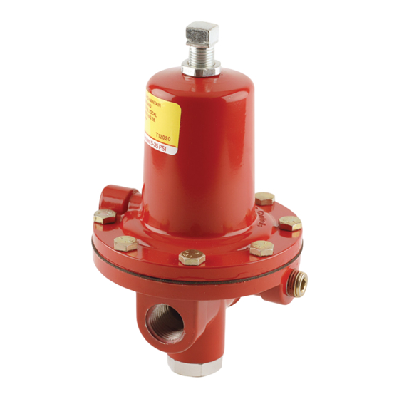
The 64 and 67C Series direct-operated regulators (Figure 1) are
designed for high-pressure (pounds per square inch) service and can
be used on either vapor applications in LP-Gas, Natural Gas and Air
or liquid LP-Gas applications. Depending upon type, outlet pressure
ranges from 3 to 135 psig (0,21 to 9,3 bar). The Type 64SR can be
used as a First Stage LP-Gas regulator–reducing tank pressure to
10 psig (0,69 bar) for a Second Stage regulator. The Type 64KB
is the only regulator in this series suitable for anhydrous ammonia
(NH
) service. The regulators are normally painted red.
3
64 and 67C Series Regulators
W8810
P1027
TYPe
64
64SR
64KB
67CW
67CH
67CD
67CN
www.emersonprocess.com/regulators/lp
67C SerieS reguLaTOrS
64 SerieS reguLaTOr
Figure 1. 64 and 67C Series Regulators
CauTiOn
Do not use the 67C, 64, or 64Sr Series regulators
in anhydrous ammonia (nH
) service. They
3
contain brass materials that are not compatible
with anhydrous ammonia (nH
Table 1. Available Configurations
DeSCriPTiOn
Basic regulator with four spring ranges from 3 to 100 psig
(0,21 to 6,9 bar).
Internal relief version with three spring ranges from 3 to 35 psig
(0,21 to 2,4 bar).
For use with anhydrous ammonia (NH
adjustment and five spring ranges from 3 to 100 psig
(0,21 to 6,9 bar). Includes a special diaphragm protector.
Basic regulator with wrench adjustment and 4 spring ranges from
3 to 135 psig (0,21 to 9,3 bar); no relief.
Basic regulator with handwheel adjustment.
Basic regulator with dial cap adjustment.
Basic regulator, factor set with not field adjustment.
).
3
) with handwheel
3
Advertisement
Table of Contents

Related Manuals for Fisher 64


Summary of Contents for Fisher 64
- Page 1 Only a qualified gas service person should install or service the regulator. Do not use the 67C, 64, or 64Sr Series regulators in anhydrous ammonia (nH ) service. They...
- Page 2 1. Regulator operation within ratings does not preclude the possibility of damage from debris in the lines or from external Some general 64 and 67C Series ratings and other specifications sources. Regulators should be inspected for damage are given on Specifications section. A spring case label gives the periodically and after any overpressure condition.
- Page 3 To avoid personal injury, property damage, equipment or exceeds maximum allowable outlet or equipment damage caused by bursting pressure of the 64 and 67C Series, then additional of pressure-containing parts or explosion of overpressure protection is required. Outlet accumulated gas, never adjust the control spring...
- Page 4 Fisher and Fisher Regulators are marks owned by Fisher Controls International, LLC. The Emerson logo is a trademark and service mark of Emerson Electric Co. All other marks are the property of their respective owners.
Need help?
Do you have a question about the 64 and is the answer not in the manual?
Questions and answers