Table of Contents
Advertisement
Instruction Manual
D100310X012
Fisherr 667 Diaphragm Actuator
Sizes 30-76 and 87
Contents
. . . . . . . . . . . . . . . . . . . . . . . . . . . . . . . . . . . .
. . . . . . . . . . . . . . . . . . . . . . . . . . . . .
. . . . . . . . . . . . . . . . . . . . . . . . . . . . . . . . .
. . . . . . . . . . . . . . . . . . . . . . . . . . . . . . .
. . . . . . . . . . . . . . . . . . . . . . . . . . . . . . . . . . . . .
. . . . . . . . . . . . . . . . . . . . . . . . . . .
. . . . . . . . . . . . . . . . . . . . . . . . .
. . . . . . . . . . . . . . . . . . . . . . . . . . . . . . . . .
. . . . . . . . . . . . . . . . . . . . . . . . . . . . . . . . . .
. . . . . . . . . . . . . . . . . . . . . . . . . . . . . . . . . . . . .
. . . . . . . . . . . . . . . . . . . . . . . . .
. . . . . . . . . . . . . . . . . . . . . . . . . . . . . . . . . . . . .
. . . . . . . . . . . . . . . . . . . . . . . . . .
Introduction
Scope of Manual
This instruction manual provides information on installation, adjustment, maintenance, and parts ordering for the
Fisher 667 actuator in sizes 30 through 76 and size 87. The 667-4 actuator in sizes 70 and 87 is also covered. Refer to
separate instruction manuals for information about the valve positioner and other accessories used with these
actuators.
Do not install, operate, or maintain a 667 actuator (see figure 1) without being fully trained and qualified in valve,
actuator, and accessory installation, operation, and maintenance. To avoid personal injury or property damage, it is
important to carefully read, understand, and follow all the contents of this manual, including all safety cautions and
www.Fisher.com
. . . . . . . . . . . . . . . . .
. . . . . . . . . . . .
. . . . . . . . . . . . . . . . . . . . . . .
. . . . . . . . .
. . . . . . . . . . . . . . . . . . . . .
. . . . . . . . . . . . . .
. . . . . . . . . . . . . . .
. . . . . . . . . . . . . . .
. . . . . . . . . . . . . . . . .
. . . . . . . .
. . . . . . . . .
. . . . . . . . . . . . . . . . . . .
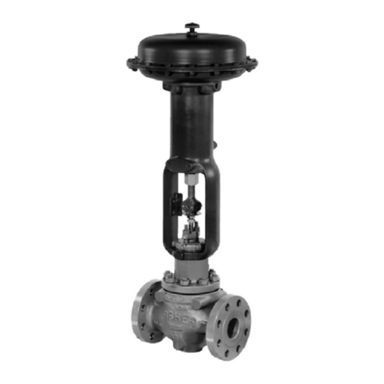
Figure 1. Fisher 667 or 667-4 Actuator Mounted on
easy-e™ Valve
1
1
2
3
3
4
5
7
8
9
11
11
12
12
15
18
19
21
23
23
23
W1916-1*
23
24
24
28
667 Size 30-76 and 87 Actuators
. . . . . . . . . . . .
. . . . . . . . . . . . . . . . .
June 2011
33
. . . .
33
35
Advertisement
Table of Contents

Related Manuals for Fisher 667


Summary of Contents for Fisher 667
-
Page 1: Table Of Contents
This instruction manual provides information on installation, adjustment, maintenance, and parts ordering for the Fisher 667 actuator in sizes 30 through 76 and size 87. The 667-4 actuator in sizes 70 and 87 is also covered. Refer to separate instruction manuals for information about the valve positioner and other accessories used with these actuators. -
Page 2: Description
The 667 actuator provides 76 mm (3 inches) maximum actuator travel. The 667-4 actuator provides 102 mm (4 inches) maximum actuator travel. Both actuators position the valve plug in response to varying pneumatic loading pressure on the diaphragm. Figure 2 shows the operation of these actuators. -
Page 3: Specifications
The side-mounted handwheel is designed for more frequent use as a manual operator. Specifications Refer to table 1 for Specifications of the 667 and 667-4 actuators. See the actuator nameplate for specific information for your actuator. WARNING To avoid personal injury or damage to equipment that may result in the malfunction of the control valve or loss of control of the process caused by excessive pressure, do not exceed the Maximum Pressures listed in table 1. -
Page 4: Installation
Instruction Manual 667 Size 30-76 and 87 Actuators June 2011 D100310X012 D Maximum Excess Diaphragm Pressure: Additional pressure may be added when the actuator is at full travel. If the Maximum Excess Diaphragm Pressure is exceeded, damage to the diaphragm or diaphragm casing might result. -
Page 5: Mounting The Actuator On The Valve
Mounting the Actuator on the Valve CAUTION The 667 actuator spring load pushes the stem down out of the actuator yoke (see figure 2), and it can come in contact with the valve stem during actuator mounting. If the valve stem is allowed to remain in the up position (towards the actuator) during actuator mounting, it can interfere with the actuator stem during mounting. - Page 6 Instruction Manual 667 Size 30-76 and 87 Actuators June 2011 D100310X012 Figure 4. Bench Set Adjustment NOTES: THE LOWER PSIG LOADING PRESSURE (MARKED ON NAMEPLATE) WHERE THE FIRST MOVE SPRING MENT OF ACTUATOR STEM IS DETECTED. ADJUSTER MARK THIS POINT WITH TAPE OR A MARKER.
-
Page 7: Discussion Of Bench Set
Instruction Manual 667 Size 30-76 and 87 Actuators D100310X012 June 2011 D Continue to lower the actuator while guiding the valve stem into the opening in the end of the actuator stem until the actuator is in place (see figure 4). -
Page 8: Spring Verification
Instruction Manual 667 Size 30-76 and 87 Actuators June 2011 D100310X012 When determining valve friction, you can make diaphragm pressure readings at a travel position other than mid-travel if you desire. If you take readings at zero or at the full travel position, take extra care to ensure that the readings are taken when the travel just begins or just stops at the position selected. -
Page 9: Installing The Stem Connector Assembly
Instruction Manual 667 Size 30-76 and 87 Actuators D100310X012 June 2011 7. Slowly increase the diaphragm pressure until the upper bench set loading pressure is applied. Again, the travel stop should be against the diaphragm casing. 8. Measure the distance between the mark or tape to the end of the actuator stem. This distance should match the travel span shown on the travel indicator scale (key 32). - Page 10 (away from the valve) movement. For push-down-to-open valves, the actuator down-stop is the limit for downward movement, and the valve seat is the limit for upward (away from the valve) movement. For 667 actuators, a down-stop (key 77, figure 6) is...
-
Page 11: Deadband Measurement
Instruction Manual 667 Size 30-76 and 87 Actuators D100310X012 June 2011 Figure 5. Typical Reverse-Acting Valve Response to Deadband OPENING VALVE UPPER BENCH SET PRESSURE RANGE OF DEADBAND 1 LOWER CLOSING BENCH SET VALVE PRESSURE OPEN CLOSED MID RANGE VALVE TRAVEL NOTE: DEADBAND IS CAUSED BY FRICTION. -
Page 12: Maintenance
Instruction Manual 667 Size 30-76 and 87 Actuators June 2011 D100310X012 1. Connect the loading pressure piping to the NPT internal connection in the side of the yoke (key 73). 2. For size 70 and 87 actuators, if necessary, remove the 1/4 NPT bushing if a 1/2 NPT internal connection is needed to increase connection size. - Page 13 Instruction Manual 667 Size 30-76 and 87 Actuators D100310X012 June 2011 from the actuator. Use lock-out procedures to be sure that the above measures stay in effect while you work on the equipment. 1. Remove the tubing or piping from the connection in the top of the yoke (key 73).
- Page 14 Instruction Manual 667 Size 30-76 and 87 Actuators June 2011 D100310X012 4. Assemble the actuator stem (key 144), lower diaphragm plate (key 71), diaphragm (key 3), upper diaphragm plate (key 4), and the travel stop cap screw and spacer (keys 12 and 2). Coat the cap screw threads with lithium grease (key 237).
-
Page 15: Top-Mounted Handwheel Assembly (Adjustable Down Travel Stop)
Instruction Manual 667 Size 30-76 and 87 Actuators D100310X012 June 2011 Top-Mounted Handwheel Assembly (Adjustable Down Travel Stop) Actuator key numbers are shown in figures 6, 7, and 8. And, top-mounted handwheels are shown in figures 9, 11, and Note If repeated or daily manual operation is expected, the actuator should be equipped with a side-mounted handwheel rather than a casing-mounted travel stop or top-mounted handwheel. - Page 16 Instruction Manual 667 Size 30-76 and 87 Actuators June 2011 D100310X012 D Turn the handwheel (key 58) to remove the handwheel screw (key 160) from the handwheel body (key 148). Remove the retaining ring (key 60) if the handwheel (key 58) must be separated from the handwheel screw.
- Page 17 Instruction Manual 667 Size 30-76 and 87 Actuators D100310X012 June 2011 Note Do not use lubricant on these bolts and nuts. Fasteners must be clean and dry. 5. Position the diaphragm casing (key 1, figures 6, 7, and 8), mounting plate (key 158), travel stops (key 152), if used, and cap screws (key 154) on the diaphragm.
-
Page 18: Side-Mounted Handwheel Assembly For Size 34 Through 60 Actuators
Instruction Manual 667 Size 30-76 and 87 Actuators June 2011 D100310X012 CAUTION Over-tightening the diaphragm cap screws and nuts (keys 13 and 14) can damage the diaphragm. Do not exceed 27 NSm (20 lbfSft) torque. Note Do not use lubricant on these bolts and nuts. Fasteners must be clean and dry. -
Page 19: Side-Mounted Handwheel Assembly For Size 70, 76, And 87 Actuators
Instruction Manual 667 Size 30-76 and 87 Actuators D100310X012 June 2011 6. Unscrew the bearing retainer (key 136) after loosening the locking set screw (key 168, not shown). 7. Pull the screw assembly (key 145) out of the handwheel body. The operating nut (key 132) will come out with the screw. - Page 20 Instruction Manual 667 Size 30-76 and 87 Actuators June 2011 D100310X012 5. Unscrew the cap screws (key 90) and remove the following connected parts: the lower diaphragm casing (key 64), the O-ring (key 70), spring case adaptor (key 89), the seal bushing, O-rings, and snap ring (keys 7, 8, 9, and 72).
-
Page 21: Casing-Mounted Travel Stops
Instruction Manual 667 Size 30-76 and 87 Actuators D100310X012 June 2011 12. Coat the O-rings (keys 8 and 9) with lithium grease (key 237), and insert them in the seal bushing (key 7). Slide the seal bushing and O-rings into the spring case adaptor (key 89). - Page 22 Instruction Manual 667 Size 30-76 and 87 Actuators June 2011 D100310X012 Casing-mounted adjustable travel stops (shown in figures 16 through 20) are available to limit travel in the down direction (extending the actuator stem) or in the up direction (retracting the actuator stem). The travel stop in figure 16 is a down travel stop, the travel stop in figure 17 is an up and down travel stop, and the travel stops in figures 18, 19, and 20 are up travel stops.
-
Page 23: Parts Kits
Use only genuine Fisher replacement parts. Components that are not supplied by Emerson Process Management should not, under any circumstances, be used in any Fisher valve, because they may void your warranty, might adversely affect the performance of the valve, and could cause personal injury and property damage. -
Page 24: Parts List
Instruction Manual 667 Size 30-76 and 87 Actuators June 2011 D100310X012 Parts List Description Part Number O-Ring Nitrile Sizes 30 through 40 1C415706992 1 Sizes 45 through 87 1E845806992 1 Note Fluorocarbon Part numbers are shown for recommended spares only. For part... - Page 25 Instruction Manual 667 Size 30-76 and 87 Actuators D100310X012 June 2011 Figure 6. Fisher 667 Actuator Sizes 30 through 60 APPLY LUBRICANT OR SEALANT 50A8379-C...
- Page 26 Instruction Manual 667 Size 30-76 and 87 Actuators June 2011 D100310X012 Figure 7. Fisher 667 Size 70 and 76 Actuator APPLY LUBRICANT 50A8598-E...
- Page 27 Instruction Manual 667 Size 30-76 and 87 Actuators D100310X012 June 2011 Figure 8. Fisher 667 Size 87 Actuator APPLY LUBRICANT 50A8600-E...
-
Page 28: Top-Mounted Handwheel
Instruction Manual 667 Size 30-76 and 87 Actuators June 2011 D100310X012 Figure 9. Top-Mounted Handwheel Assembly for Size 30 through 40 Actuators APPLY LUBRICANT NOTE: THE TOP MOUNTED HANDWHEEL IS NOT DESIGNED FOR USE UNDER HEAVY LOAD OR FREQUENT USE. - Page 29 Instruction Manual 667 Size 30-76 and 87 Actuators D100310X012 June 2011 Figure 10. Top-Mounted Handwheel Assembly, Style P2 for Size 45, 50, 60, and 76 Actuators APPLY LUBRICANT 30B3942-A...
-
Page 30: Actuators
Instruction Manual 667 Size 30-76 and 87 Actuators June 2011 D100310X012 Figure 11. Top-Mounted Handwheel Assembly for Size 45-76 Actuators APPLY LUBRICANT 33B9224-B... -
Page 31: Actuators
Instruction Manual 667 Size 30-76 and 87 Actuators D100310X012 June 2011 Figure 12. Top-Mounted Handwheel Assembly for Size 70 and 87 Actuators APPLY LUBRICANT CV8060-J... -
Page 32: Actuators
Instruction Manual 667 Size 30-76 and 87 Actuators June 2011 D100310X012 Figure 13. Side Mounted Handwheel Assembly for Size 34 and 40 Actuators APPLY LUBRICANT 30A8778-D Figure 14. Side-Mounted Handwheel Assembly for Size 45 through 60 Actuators APPLY LUBRICANT 40A8779-D... -
Page 33: Side-Mounted Handwheel (34-60)
Instruction Manual 667 Size 30-76 and 87 Actuators D100310X012 June 2011 Side-Mounted Handwheel, Side-Mounted Handwheel, Size 34-60 (figures 13 and 14) Size 70, 76 and 87 (figure 15) Description Description Handwheel Handgrip Hex Jam Nut Handgrip Bolt Ball Worm Gear... - Page 34 Instruction Manual 667 Size 30-76 and 87 Actuators June 2011 D100310X012 Figure 15. Size 70, 76, and 87 Actuator with Side Mounted Handwheel Assembly PART NOT SHOWN: 57 APPLY LUBRICANT E0871...
-
Page 35: Casing Mounted Travel Stops
Instruction Manual 667 Size 30-76 and 87 Actuators D100310X012 June 2011 Casing-Mounted Travel Stops Description Part Number Screw, Cap, Hex Hd (figures 16 through 20) Washer Vent Description Part Number Guide Plate Mounting Plate Handwheel Nut, Travel Stop Plug, Pipe... -
Page 36: Actuators
AV8096-B Fisher and easy-e are marks owned by one of the companies in the Emerson Process Management business division of Emerson Electric Co. Emerson Process Management, Emerson, and the Emerson logo are trademarks and service marks of Emerson Electric Co. All other marks are the property of their respective owners.
Need help?
Do you have a question about the 667 and is the answer not in the manual?
Questions and answers