Table of Contents
Advertisement
Instruction Manual
D100324X012
Fisher
1061 Pneumatic Piston Rotary Actuator
™
with Style F & G Mounting Adaptations
Contents
. . . . . . . . . . . . . . . . . . . . . . . . . . . . . . . . .
. . . . . . . . . . . . . . . . . . . . . . . . . . . . .
. . . . . . . . . . . . . . . . . . . . . . . . . . . . . . . . .
. . . . . . . . . . . . . . . . . . . . . . . . . . . . . . .
. . . . . . . . . . . . . . . . . . . . . . . . . . . . . . . . . .
. . . . . . . . . . . . . . . . . . . . . . . . . .
. . . . . . . . . . . . . . . . . . . . . . . . . . . . . . . . . .
. . . . . . . . . . . . . . . . . . . . . . . . . . . . . . . .
. . . . . . . . . . . . . . . . . . . . . . . . . . . . . . .
. . . . . . . . . . . . . . . . . . . . . . . . . . . . . . . . . .
. . . . . . . . . . . . . . . . . . . . . . . . . .
. . . . . . . . . . . . . . . . . . . . . . . . . . . . . .
. . . . . . . . . . . . . . . . . . . . . . . . . . . . . . .
. . . . . . . . . . . . . . . . . . . . . . . . . . . . . . . . . . .
. . . . . . . . . . . . . . . . . . . . . . . . .
. . . . . . . . . . . . . . . . . . . . . . . . . . . . . . . . . . .
Introduction
Scope of Manual
This instruction manual includes installation, adjustment, maintenance, and parts ordering information for the Fisher
1061 pneumatic piston rotary actuator with F and G mounting adaptations (see figure 1). Instructions for the control
valve, the auxiliary declutchable handwheel actuator, the valve positioner, and accessories are covered in separate
instruction manuals.
Do not install, operate, or maintain a 1061 actuator without being fully trained and qualified in valve, actuator, and
accessory installation, operation, and maintenance. To avoid personal injury or property damage, it is important to
carefully read, understand, and follow all the contents of this manual, including all safety cautions and warnings. If you
have any questions about these instructions, contact your
proceeding.
www.Fisher.com
. . . . . . . . . . . . . . . . . . . . . . . . .
. . . . . . . . . . . . . . . . . . . . . . . . .
. . . . . . . . . . . . . . . . . .
. . . . . . . . . . . . . . . . . . . . . . . .
. . . . . . . . . . . . .
. . . . . . . . . . . .
. . . . . . . . . . . . . . . . . .
. . . . . . . . . . . . . . . . . . . . .
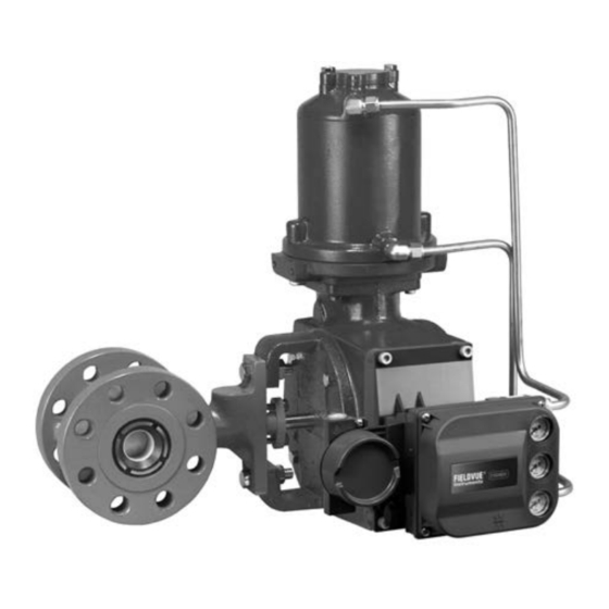
Figure 1. Fisher 1061 Actuator with V500 Valve and
DVC6200 FIELDVUE™ Digital Valve Controller
1
1
2
2
3
3
3
3
8
9
9
10
11
12
14
15
16
18
19
W8380−2
19
19
19
19
19
Emerson sales office
1061 F & G Actuator
. . . . . . . . . . . . . . . . . . . .
. . . . . . . . . . . . . . . . . . . . . . . .
. . . . . . . . . . . .
or Local Business Partner before
June 2017
20
20
20
Advertisement
Table of Contents

Related Manuals for Fisher 1061


Summary of Contents for Fisher 1061
-
Page 1: Table Of Contents
Do not install, operate, or maintain a 1061 actuator without being fully trained and qualified in valve, actuator, and accessory installation, operation, and maintenance. To avoid personal injury or property damage, it is important to carefully read, understand, and follow all the contents of this manual, including all safety cautions and warnings. -
Page 2: Description
The 1061 actuator is a double‐acting pneumatic piston rotary actuator for use with rotary‐shaft valves having splined valve shafts. The 1061 actuator can be used for either throttling or on‐off applications. The style G mounting bracket is for Fisher 9500 valves only. The style F mounting bracket is for all other rotary valves. Specifications Specifications are shown in table 1 for 1061 actuators. -
Page 3: Educational Services
1061 F & G Actuator D100324X012 June 2017 Educational Services For information on available courses for 1061 Style F and G actuators, as well as a variety of other products, contact: Emerson Automation Solutions Educational Services - Registration Phone: 1-641-754-3771 or 1-800-338-8158 E-mail: education@emerson.com... - Page 4 Instruction Manual 1061 F & G Actuator June 2017 D100324X012 1. Refer to instructions in the appropriate valve instruction manual. 2. If a valve positioner is installed on the actuator, remove the positioner. On the travel indicator side of the actuator: 3.
- Page 5 Instruction Manual 1061 F & G Actuator D100324X012 June 2017 VALVE SERIES OR DESIGN VALVE SERIES OR DESIGN BALL/PLUG DISK/BALL 8510B, 8532, MOUNTING ACTION CV500 ROTATION TO V250 V150, V200 & V300 ROTATION TO V250 8560 V500 CLOSE CLOSE & 9500 PDTC Right‐Hand...
- Page 6 Instruction Manual 1061 F & G Actuator June 2017 D100324X012 Table 2. Bolting Torque Values for Valve Mounting Cap Screws VALVE SHAFT DIAMETER VALVE MOUNTING CAP SCREWS Inch lbf‐ft 12.7 to 25.4 1/2 to 1 31.8 & 38.1 1‐1/4 & 1‐1/2 44.5 &...
- Page 7 Instruction Manual 1061 F & G Actuator D100324X012 June 2017 D For all sizes: Hold the lever in position, and secure the assembly with the cap screw (key 29). 14. Rotate the lever until the cap screw hole is aligned with the rod end bearing (key 12). You may need to adjust the turnbuckle to make this alignment.
-
Page 8: Changing Actuator Mounting
If a manual handwheel actuator is to be used, refer to the separate instruction manual for mounting instructions. 18. If the 1061 actuator is equipped with an auxiliary handwheel actuator, make certain that a cylinder bypass valve (key 68, figure 10) is also used to equalize cylinder pressure during handwheel operation. Operating the handwheel actuator by itself against the force of differential cylinder pressures is difficult or even impossible. -
Page 9: Pressure Connections
Adjustment The only adjustment on the 1061 actuator is to make sure that the valve disk or ball is correctly closed when the actuator piston is against the travel stop. For accurate adjustment to the zero‐degree valve disk or ball position, you must remove the control valve from the pipeline. -
Page 10: Maintenance
If using a handwheel actuator, the valve shaft spline could be damaged if excessive torque is applied to the valve shaft by the manual actuator while the 1061 power actuator is stopped at either end of travel. To protect the valve shaft, perform the travel stop adjustment procedure found in the separate handwheel actuator instruction manual. -
Page 11: Disassembly
Instruction Manual 1061 F & G Actuator D100324X012 June 2017 D Always wear protective gloves, clothing, and eyewear when performing any maintenance operations to avoid personal injury. D Disconnect any operating lines providing air pressure, electric power, or a control signal to the actuator. Be sure the actuator cannot suddenly open or close the valve. -
Page 12: Assembly
Instruction Manual 1061 F & G Actuator June 2017 D100324X012 8. For size 30, 40, and 68 actuators, unscrew cap screws (key 6) and remove cylinder cap (key 4). Inspect and, if necessary, replace the O‐ring (key 5). 9. Remove rod end bearing (key 12) and hex nut (key 11), remove the turnbuckle (key 70) and hex nut (key 71). - Page 13 Instruction Manual 1061 F & G Actuator D100324X012 June 2017 4. Refer to figure 2 for the desired orientation of the housing (key 21). Secure the housing to the mounting yoke with the cap screws (key 24). 5. Apply lithium grease lubricant (key 93) to the surfaces of the sliding seal (key 19). Refer to torque values shown in table 3.
-
Page 14: Locking Mechanism
Instruction Manual 1061 F & G Actuator June 2017 D100324X012 piston rod. Consult your Emerson sales office or Local Business Partner for additional information to properly assemble these parts. e. Tighten the screw or nut to the torque specified in table 3. -
Page 15: Installing The Locking Mechanism
Instruction Manual 1061 F & G Actuator D100324X012 June 2017 Figure 5. Locking Mechanism (Size 30, 40, 60, and 68) LEVER MODIFIED HOUSING (KEY 20) LEVER CAP SCREW GROOVE PIN (KEY 127) MOUNTING PLATE (KEY 123) PADLOCK (CUSTOMER SUPPLIED) CAP SCREW (4 REQ'D) (KEY 129) -
Page 16: Operating The Locking Mechanism
130). If the shackle of the padlock does not seem long enough, do not attempt to modify the actuator. The larger 1061 sizes may require a padlock with a longer shackle. 8. Refer to the Operating the Locking Mechanism section. - Page 17 4. Insert and lock the padlock (not furnished) to connect the mounting plate (key 123) with the arm of the safety lockout (key 130). The larger 1061 sizes may require a padlock with a longer shackle.
-
Page 18: Pipe-Away Vent
Instruction Manual 1061 F & G Actuator June 2017 D100324X012 Pipe‐Away Vent Some applications require venting of gas from the rotary actuator housing. The 3610 Series positioners vent into the actuator housing, and from there, the gas has numerous avenues of escape. -
Page 19: Parts Ordering
Use only genuine Fisher replacement parts. Components that are not supplied by Emerson Automation Solutions should not, under any circumstances, be used in any Fisher valve, because they may void your warranty, might adversely affect the performance of the valve, and could cause personal injury and property damage. -
Page 20: Locking Mechanism Parts
Instruction Manual 1061 F & G Actuator D100324X012 June 2017 Description Description O Ring Travel Indicator Anti‐Seize Sealant Self‐Tapping Screw Thread Locking Adhesive (medium strength) Cap Screw Lithium Grease Lubricant Positioner plate Thrust Washer Cap Screw Nameplate Drive Screw Locking Mechanism Parts (figure 5 or 6) - Page 21 Instruction Manual 1061 F & G Actuator D100324X012 June 2017 Figure 7. Pipe‐Away Vent Assembly DRILL SIZE IS 6.4 TO 6.8 BY 14.7 mm DRILL SIZE IS 3.7 TO 4.0 BY 14.2 mm DEEP (0.252 TO 0.269 BY 0.58‐INCH ).
- Page 22 Instruction Manual 1061 F & G Actuator June 2017 D100324X012 Figure 8. Typical Assembly for Fisher 1061 Sizes 30 through 68 Actuators 58A9228‐C NOTES: KEYS 56, 87, AND 141 ARE NOT SHOWN V APPLY LUBRICANT OR SEALANT Figure 9. Typical Assembly for Fisher 1061 Size 80 and 100 Actuators...
-
Page 23: D100324X012 June
Instruction Manual 1061 F & G Actuator D100324X012 June 2017 Figure 10. Partial View of Actuator with Bypass Valve 54A5326‐K... - Page 24 Responsibility for proper selection, use, and maintenance of any product remains solely with the purchaser and end user. Fisher and FIELDVUE are marks owned by one of the companies in the Emerson Automation Solutions business unit of Emerson Electric Co. Emerson Automation Solutions, Emerson, and the Emerson logo are trademarks and service marks of Emerson Electric Co.
Need help?
Do you have a question about the 1061 and is the answer not in the manual?
Questions and answers