Table of Contents
Advertisement
Quick Links
Instruction Manual
D101402X012
Fisherr 3660 and 3661 Positioners
Contents
. . . . . . . . . . . . . . . . . . . . . . . . . . . . . . . . .
. . . . . . . . . . . . . . . . . . . . . . . . . . . . .
. . . . . . . . . . . . . . . . . . . . . . . . . . . . . . . . .
. . . . . . . . . . . . . . . . . . . . . . . . . . . . . . .
. . . . . . . . . . . . . . . . . . . . . . . . .
. . . . . . . . . . . . . . . . . . . . . . . . . . . . . . . . . .
. . . . . . . . . . . . . . . . . . . . . . . . . . . . . . . . . . . .
FM
. . . . . . . . . . . . . . . . . . . . . . . . . . . . . . . . . . . . .
. . . . . . . . . . . . . . . . . . . . . . . . . . . . . . . . . . .
. . . . . . . . . . . . . . . . . . . . . . . . . . . . . . . . . . .
. . . . . . . . . . . . . . . . . . . . . . . . .
. . . . . . . . . . . . . . . . . . . . . . . . . . .
. . . . . . . . . . . . . . . . . . . . . . . . . . . . . . . . . .
. . . . . . . . . . . . . . . . . . . . . . . .
. . . . . . . . . . . . . . . . . . . . . . . . . . . . . . . .
. . . . . . . . . . . . . . . . . . . . . . . . .
www.Fisher.com
. . . .
. . . . . . . . . . . . . . . . . . . . . .
. . . . . . . .
. . . . . . .
. . . . . . . . . . . . . . . . . .
. . . . . . . . . . . . . . . . . . . . . . .
. . . . . . . . . . . . . . . . . . . . . .
. . . . . . . . . . . . . . . . . . . . . .
. . . . . . . . . . . . . . . . . .
. . . . . . . . . . . . . . . . . .
. . . . .
. . . . . . . . . . . . . . . . . . . . . . .
. . . . . . . . . . . . . . . . . . . . . . .
. . . . . . . . . . . . . . .
. . . . . . . . . . . . . . . . . .
. . . . .
. . . . . . . . .
. . . . . . . . . . . . . . . . . .
. . . . . . . . . . . . . . . .
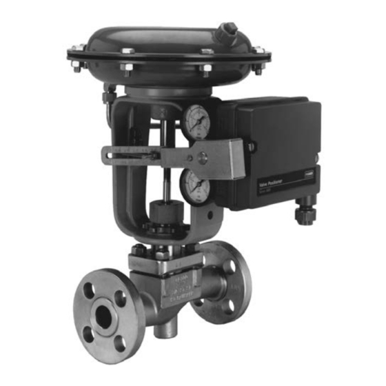
Figure 1. Fisher 3660 Positioner Mounted on a
Baumann Actuator
2
2
2
2
2
5
5
5
6
6
7
8
8
12
13
16
19
19
21
W7174
21
21
22
22
23
25
26
27
28
29
. . . . . . . . . . . . . . . . . . . . . . . . . . . . . . . . . . .
29
29
. . . . . . . . . . . . . . . . . . . . . . . . . . . . . . . . . . .
29
29
. . . . . . . . . . . . . . . . . . . . . . . . . . . . . . . . . . .
30
30
3660 and 3661 Positioners
. . . . . . . . . . . . . . . . . . . . .
. . . . . . . . . . . . . . . . . . . . . . . . . . . .
. . . . . . . . . . . . . . . . . . . . . . . . . . . . . . .
. . . . . . . . . . . . . . . . . . . . . . . . . . . . . . . . .
. . . . . . . . . . . . . . . . . . . . . . . . . . . . . .
. . . . . . . . . . . . . . . . . . . .
. . . . . . . . . . . . . . . . . . . . .
. . . . . . . . . . . . . . . . . . . . . . . . . . . . .
September 2015
30
31
32
. . . . . . . . .
33
33
34
34
34
34
34
39
39
. . . . . . . . . . .
42
Advertisement
Table of Contents

Subscribe to Our Youtube Channel
Related Manuals for Fisher 3660


Summary of Contents for Fisher 3660
-
Page 1: Table Of Contents
September 2015 Fisherr 3660 and 3661 Positioners Contents Figure 1. Fisher 3660 Positioner Mounted on a Baumann Actuator Introduction ....... . . -
Page 2: Introduction
Fisher 3660 and 3661 positioners. Refer to separate instruction manuals for information on the actuator and control valve. Do not install, operate, or maintain a 3660 or 3661 positioner without being fully trained and qualified in valve, actuator and accessory installation, operation and maintenance. To avoid personal injury or property damage it is important to carefully read, understand, and follow all of the contents of this manual, including all safety cautions and warnings. - Page 3 0.16% of travel Medium: Air 3660 and 3661 are not compatible with natural gas Operative Temperature Limits as the supply medium 3660 without Pressure Gauges: -40 to 121°C (-40 to 250°F) Performance 3660 with Pressure Gauges: -40 to 82°C...
- Page 4 1/4 NPT internal Other Classifications/Certifications for 3661 Options CUTR—Customs Union Technical Regulations (Russia, 3660: J Instrument and output pressure gauges, Kazakhstan, Belarus, and Armenia) J Integrally mounted bypass valve INMETRO— National Institute of Metrology, Quality, and Technology (Brazil) 3661: Output pressure gauge KGS—Korea Gas Safety Corporation (South Korea)
-
Page 5: Installation
Instruction Manual 3660 and 3661 Positioners D101402X012 September 2015 Installation Typically, a positioner is shipped with the actuator. If so, the factory mounts and calibrates the positioner and connects the positioner to actuator tubing. If the positioner is ordered separately from the actuator, perform the appropriate mounting procedure. -
Page 6: Atex
Instruction Manual 3660 and 3661 Positioners September 2015 D101402X012 Table 3. Hazardous Area Classifications for Fisher 3661 Positioner—CSA (Canada) Certification Body Certification Obtained Entity Rating Temperature Code Vmax = 30 VDC Intrinsically Safe T4 (Tamb ≤ 82°C) Imax = 150 mA Ex ia IIC T4/T5/T6 per drawing GE28591 (see figure 27) T5 (Tamb ≤... -
Page 7: Iecex
Instruction Manual 3660 and 3661 Positioners D101402X012 September 2015 Table 5. Hazardous Area Classifications for Fisher 3661 Positioner—ATEX Certificate Certification Obtained Entity Rating Temperature Code Ui = 30 VDC II 1 G T4 (Tamb ≤ 82°C) Ii = 150 mA Intrinsically Safe T5 (Tamb ≤... -
Page 8: Positioner Mounting
Figure 3 shows keys 64 through 78 and 101 through 104. Other key numbers are shown in either figure 24 for the 3660 positioner or figure 25 for the 3661 positioner. Two mounting methods are available, center‐bolt mounting and clamp mounting. - Page 9 Instruction Manual 3660 and 3661 Positioners D101402X012 September 2015 Figure 2. Mounting Configurations Input Signal Positioner Output Direct 0.2 to 1.0 bar (3 to 15 psig) 0.4 to 2.0 bar (6 to 30 psig) 4 to 20 mA Reverse Up to 6.2 bar (90 psig) 1.0 to 0.2 bar (15 to 3 psig)
- Page 10 Instruction Manual 3660 and 3661 Positioners September 2015 D101402X012 Figure 3. Positioner Mounting on Fisher 1250, 1250R, and 3024S Actuators CENTER BOLT MOUNT NIPPLE MOUNTED FILTER REGULATOR CLAMP MOUNT SECTION A‐A FEEDBACK WEDGE NUT PLATE (KEY 104) (KEY 68) FEEDBACK...
- Page 11 Instruction Manual 3660 and 3661 Positioners D101402X012 September 2015 Figure 4. Feedback Plate Orientation with Positioner Mounted on Fisher 1250, 1250R, and 3024S Actuators POSITIONER POSITIONER STEM CONNECTOR ACTUATOR LEG STEM CONNECTOR ACTUATOR LEG FEEDBACK FEEDBACK PLATE PLATE FEEDBACK LEVER...
-
Page 12: Mounting On Baumannt Actuators
Mounting on Baumann Actuators During the following mounting procedures, refer to figures 2, 5, 6, 24, and 25. Key numbers are shown in either figure 24 for the 3660 positioner or figure 25 for the 3661 positioner. Figure 5. Actuator Center‐Bolt Mounting Figure 6. -
Page 13: Mounting On 657 And 667 Actuators
During the following mounting procedures, refer to figures 7, 24, and 25 for key number locations. Figure 7 shows keys 69 and 70, 73 through 78, and 82 through 93. Other key numbers are shown in either figure 24 for the 3660 positioner or figure 25 for the 3661 positioner. - Page 14 Instruction Manual 3660 and 3661 Positioners September 2015 D101402X012 Figure 7. Positioner Mounting on Fisher 657 and 667 Actuators TO POSITIONER OUTPUT FILTER REGULATOR NIPPLE MOUNTED FILTER REGULATOR SECTION A‐A APPLY LUB 41B6744‐D...
- Page 15 Instruction Manual 3660 and 3661 Positioners D101402X012 September 2015 Figure 8. Feedback Arm Orientation with Positioner Mounted on Fisher 657 and 667 Actuators POSITIONER VALVE STEM STEM CONNECTOR POSITIONER STEM CONNECTOR ACTUATOR LEG ACTUATOR STEM ACTUATOR STEM ACTUATOR LEG CONNECTOR...
-
Page 16: Feedback Lever Assembly And Range Spring Installation
11. Install the feedback lever assembly and range spring. Feedback Lever Assembly and Range Spring Installation Key numbers are shown in either figure 24 for the 3660 positioner or figure 25 for the 3661 positioner. Key numbers for the feedback lever assembly are shown in figure 26. - Page 17 Instruction Manual 3660 and 3661 Positioners D101402X012 September 2015 Figure 9. Installing the Feedback Lever Assembly Figure 10. Positioning Feedback Spring (Key 19) on the Positioner FEEDBACK SPRING MUST HOOK AROUND SPRING SPRING PIN PIN END OPPOSITE THE ZERO ADJUSTMENT SCREW ANTI‐ROTATING SLOT...
- Page 18 Instruction Manual 3660 and 3661 Positioners September 2015 D101402X012 Figure 11. Range Spring Installation Figure 12. Range Spring Alignment STRAIGHT PORTION RANGE SPRING OF SPRING FEEDBACK SHAFT LEVER ASSEMBLY BOSS SLOT SECTION A FEEDBACK LEVER SHAFT W7366 ASSEMBLY A5211 CAUTION Installation of the feedback lever assembly (key 19) prior to installation of the range spring (key 30) may result in damage to the lever assembly (key 17) flexures.
-
Page 19: Pressure Connections
CAUTION The O‐rings used in 3660 and 3661 positioners are made of EPDM (ethylene propylene). Use a clean, dry, oil‐free air supply with instruments containing EPDM components. EPDM is subject to degradation when exposed to petroleum‐based... - Page 20 Instruction Manual 3660 and 3661 Positioners September 2015 D101402X012 Figure 15. Typical Mounting Dimensions and Connections ACTUATOR CENTERLINE TO POSITIONER Dimension X Type Size Inch 92.2 3.63 95.3 3.75 657/667 104.9 4.13 45/46 108.0 4.25 50/60 128.5 5.06 86.0 3.39 1250 86.0...
-
Page 21: Output Connection
Instruction Manual 3660 and 3661 Positioners D101402X012 September 2015 Connect a clean, dry, oil‐free air source to the supply connection of the positioner. Use 3/8‐inch tubing or 1/4 NPT pipe for the supply line. A supply air filter or a filter regulator capable of removing particles 40 micrometers in diameter is recommended. -
Page 22: Vent Connection
2. Turn the pipe tee to position the connector body and body protector for easy access when doing the diagnostic testing. Vent Connection 3660 and 3661 positioners are equipped with a 1/4 NPT vent connection in the cover. Electrical Connections for 3661 Positioners WARNING For intrinsically safe installations, refer to the loop schematics shown in figures 27 and 28, factory drawings, or to instructions provided by the barrier manufacturer for proper wiring and installation. -
Page 23: Calibration
During calibration the valve may move. To avoid personal injury and property damage caused by the release of pressure or process fluid, provide some temporary means of control for the process. Refer to figure 24 (3660) or figure 25 (3661) for key number locations unless otherwise indicated. Adjustment locations are shown in figure 19. - Page 24 Instruction Manual 3660 and 3661 Positioners September 2015 D101402X012 Figure 19. Adjustment Locations (Equivalents of Pressures Shown in This Drawing are: 6 bar = 86 psig, 4 bar = 58 psig, and 1.4 bar = 20 psig) REFER TO INSTRUCTION MANUAL FOR...
-
Page 25: Split Range Operation
Split‐Range Operation 3660 and 3661 positioners can be used for split‐range operation with the instrument input signal from a single controller or another instrument split between two or three control valves. Tables 7 and 8 show some typical split ranges for the positioners. -
Page 26: 3660 Bypass Operation
LOCATION 38B0195‐B 3660 Bypass Operation 3660 positioners may be supplied with a bypass assembly. CAUTION Do not use bypass operation when the positioner is reverse acting or is in split‐range operation. In these cases, bypassing the positioner sends the input signal directly to the actuator. Such a change will affect the desired operation and possibly... -
Page 27: Principle Of Operation
Instruction Manual 3660 and 3661 Positioners D101402X012 September 2015 upset the system. Use bypass operation only when the instrument signal range is the same as the positioner output range required for normal actuator operation. Labels on the bypass body assembly (key 41, figure 23), and a pointer on the bypass lever (key 42 in figure 23) indicate if the input signal from the instrument goes to the positioner or directly to the control valve actuator. -
Page 28: Maintenance
Instruction Manual 3660 and 3661 Positioners September 2015 D101402X012 Figure 21. Operational Schematic FLAPPER DIRECT ACTING OUTPUT PIVOT NOZZLE RANGE REVERSE RELAY SPRING ACTING PIVOT SECTION A‐A GAIN ADJ SUPPLY RANGE RELAY SPRING GAIN ADJ PILOT PIVOT SHAFT BEAM FEEDBACK... -
Page 29: Changing The Positioner Action
4. Refer to the Calibration section for the calibration procedure. Changing the Input Signal Range on 3660 Positioners To change the input signal range from 0.2 to 1.0 bar (3 to 15 psig) to 0.4 to 2.0 bar (6 to 30 psig) or vice versa, change the input diaphragm assembly (key 28, figure 24) by performing the Changing the Input Module Diaphragm Assembly procedure in this Maintenance section. -
Page 30: Clamp Mounting On 1250, 1250R And 3024S Actuators
Instruction Manual 3660 and 3661 Positioners September 2015 D101402X012 1. Release all pressure from the positioner. Disconnect the supply, instrument, and output tubing. For 3661 positioners, disconnect the input wires and conduit. 2. Unscrew the two captive cover screws and remove the cover (keys 24 and 21). Loosen the retaining screw (key 19P). -
Page 31: Disassembling And Assembling Relay Components
Instruction Manual 3660 and 3661 Positioners D101402X012 September 2015 6. With the input pressure set at either 1.4 or 2.4 bar (20 or 35 psig), check for leaks between the diaphragm assembly and the housing. 7. Refer to the Calibration section for the calibration procedure. -
Page 32: Disassembling And Assembling The Bypass Valve
Disassembling and Assembling the Bypass Valve During the following bypass valve disassembly and assembly procedures, refer to figure 23, unless otherwise indicated. Figure 23. Fisher 3660 Bypass Valve 11B3925‐B 1. Remove all pressure from the positioner. Disconnect the supply, instrument and output tubing. -
Page 33: Replacing The 3661 Converter Module
Instruction Manual 3660 and 3661 Positioners D101402X012 September 2015 8. Install the three O‐rings (key 49) into the body assembly (key 41) and then carefully attach the body assembly to the positioner using the two cheese head screws (key 47). -
Page 34: Parts Kits
These kits contain keys 9, 26, 27, 28, 29, 43, 44, 45, 49, 95, and 97. Keys 43, 44, 45 and 49 are used for the 3660 with bypass only. An additional O‐ring is included in kit R3660X00012, but is not used for the 3660. Note Contact your... - Page 35 19F Zero Shaft 3660 and 3661 19G Slide Bearing (2 req'd) 0.2 to 1.0 bar (3 to 15 psig) 19H Housing Bushing 3660 only, 0.4 to 2.0 bar (6 to 30 psig) Retaining Ring 29* Output diaphragm assembly, aluminum 19K Disc O‐ring 30...
- Page 36 Dual scale Note 0 to 2 Kg/cm 0 to 30 psig 11B4036X042 Keys 41 through 49 and key 79 apply to 3660 with bypass valve only. 0 to 11 Kg/cm 0 to 160 psig 11B4036X062 Refer to figure 23. Triple scale 0 to 2 bar/0 to 0.2 MPa/0 to 30 psig...
- Page 37 Instruction Manual 3660 and 3661 Positioners D101402X012 September 2015 Figure 25. Fisher 3661 Positioner Assembly VIEW D‐D SECTION C‐C VIEW A‐A WITH M20 CABLE GLAND VIEW A‐A 51B3945‐J WITHOUT COVER...
- Page 38 Description Description 51 Adhesive, Loctite 4210t Prism Instant Adhesive, 79 Wire tie for 3660 with bypass valve only, (not furnished with positioner) plastic 54 Self‐tapping screw, stainless steel (2 req'd) 95* O‐ring, EPDM 55 Cover plate for 3661, A95052 (2 req'd for 3660;...
-
Page 39: Diagnostic Connections
Instruction Manual 3660 and 3661 Positioners D101402X012 September 2015 Diagnostic Connections Description 77 Cap screw, pl steel (2 req'd) FlowScanner Valve Diagnostic System Hookup For 657, 667, 1250, 1250R, 3024S and GX Includes pipe tees, pipe nipples, pipe bushings, connector bodies, and body protectors. - Page 40 Instruction Manual 3660 and 3661 Positioners September 2015 D101402X012 Description Description 84 U‐bolt, stainless steel (2 req'd) 3024C Actuator Sizes 50 and 60 Sizes 30, 34, 40, 45 and 46 85 Washer, stainless steel (4 req'd) 68 Feedback Plate 86 Hex nut, stainless steel (4 req'd) 69...
- Page 41 Instruction Manual 3660 and 3661 Positioners D101402X012 September 2015 Figure 26. Feedback Lever Assembly 28B9418‐B STANDARD 28B9423‐B FOR Baumann ACTUATORS...
-
Page 42: Loop Schematics For 3661 Positioners
Instruction Manual 3660 and 3661 Positioners September 2015 D101402X012 Loop Schematics for 3661 Positioners This section includes loop schematics required for wiring of intrinsically safe installations. If you have any questions, contact your Emerson Process Management sales office. Figure 27. CSA Loop Schematic for Fisher 3661 Positioner (Drawing GE28591) - Page 43 Instruction Manual 3660 and 3661 Positioners D101402X012 September 2015 Figure 28. FM Loop Schematic for Fisher 3661 Positioner (Drawing GE28590) HAZARDOUS LOCATION NON-HAZARDOUS LOCATION INTRINSIC SAFETY CLASS I, II, III, DIV 1, GROUPS A,B,C,D,E,F,G CLASS I ZONE 0 AEx ia IIC...
-
Page 44: D101402X012 September
Instruction Manual 3660 and 3661 Positioners D101402X012 September 2015 Neither Emerson, Emerson Process Management, nor any of their affiliated entities assumes responsibility for the selection, use or maintenance of any product. Responsibility for proper selection, use, and maintenance of any product remains solely with the purchaser and end user.
Need help?
Do you have a question about the 3660 and is the answer not in the manual?
Questions and answers