Table of Contents
Advertisement
Quick Links
Advertisement
Table of Contents

Related Manuals for Dräger REGARD


Summary of Contents for Dräger REGARD
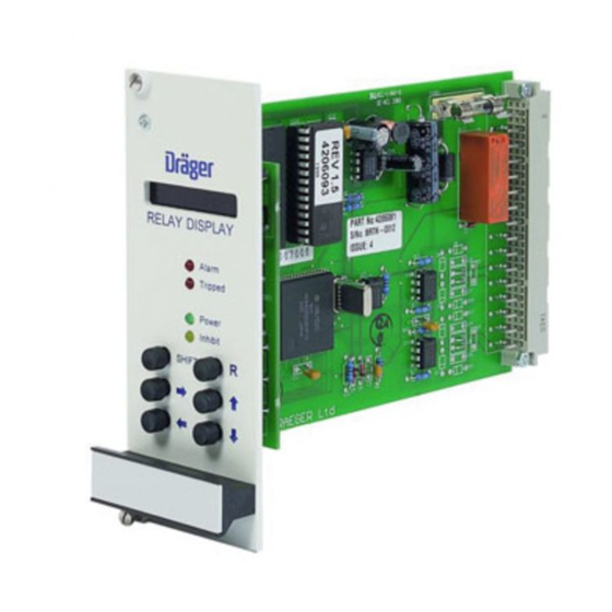
- Page 1 REGARD GAS DETECTION SYSTEM 8-INPUT 4-20 MODULE 8-CHANNEL DISPLAY CARD (ATEX VERSION) h1 : 0 8-CHANNEL DISPLAY Fault Power Inhibit SHIFT INSTRUCTIONS FOR USE...
- Page 2 REGARD 8-Input 4-20 Module & 8-Channel Display Card (ATEX Version) Issue 2. October 2011...
-
Page 3: Table Of Contents
REGARD 8-Input 4-20 Module & 8-Channel Display Card (ATEX Version) CONTENTS FOR YOUR SAFETY OPERATION Intended use Description General Power-on sequence Command mode Master card Modbus gateway card Electromagnetic compatibility (EMC) Display card front panel controls and indicators Display LEDs... - Page 4 REGARD 8-Input 4-20 Module & 8-Channel Display Card (ATEX Version) Set relay energise state Set zero drift band Set under-range fault level Set over-range fault level Set alarm hysteresis Set user-definable text Gas level display on / off Set LEDs to display master alarms or per head alarms...
-
Page 5: For Your Safety
REGARD 8-Input 4-20 Module & 8-Channel Display Card (ATEX Version) FOR YOUR SAFETY Follow the instructions Follow the instructions for installation, operation and maintenance. Use in areas subject to explosion hazards The 8-input 4-20 module and 8-channel display card are not designed for use in a flammable atmosphere without suitable protection. -
Page 6: Operation
REGARD 8-Input 4-20 Module & 8-Channel Display Card (ATEX Version) OPERATION Intended use 8-channel display card and 8-input 4-20 module provide: REGARD • Measurement and display of gas level with gas measuring heads (transmitters) such as Polytron 2. The equipment can be used with any 4-20mA transmitter. -
Page 7: Command Mode
For more information refer to the Regard Modbus Gateway Card Operating Manual. Electromagnetic compatibility (EMC) The Regard 8-input 4-20 module and display card have been tested for compliance with the EMC Directive. Take the following steps to ensure compliance: • Installation must follow the instructions given in this manual. -
Page 8: Display Card Front Panel Controls And Indicators
REGARD 8-Input 4-20 Module & 8-Channel Display Card (ATEX Version) Display card front panel controls and indicators Display Display normally shows gas level of each head in sequence. When an alarm occurs, display shows gas level of head(s) in alarm only. -
Page 9: Input Module Terminals
REGARD 8-Input 4-20 Module & 8-Channel Display Card (ATEX Version) Input module terminals DC INPUT 1 DC INPUT 2 RS-485 OUTPUT 4-20mA INPUT 1 4-20mA INPUT 2 4-20mA INPUT 3 4-20mA INPUT 4 4-20mA INPUT 5 4-20mA INPUT 6 4-20mA INPUT 7 4-20mA INPUT 8 Issue 2. -
Page 10: Operational Faults
REGARD 8-Input 4-20 Module & 8-Channel Display Card (ATEX Version) Operational faults An operational fault is a failure in operation of either the display card or input module. Operational faults are either • critical – card may stop working, or •... - Page 11 REGARD 8-Input 4-20 Module & 8-Channel Display Card (ATEX Version) Fault code Meaning Remedy FAULT BR Push button fault. Advisory. Check push buttons. FAULT BS Push button indicated appears to be continuously pressed. FAULT B FAULT B FAULT B FAULT B...
-
Page 12: Installation
Handle circuit boards with care during installation. Do not touch the circuit board or components. Take anti-static precautions were necessary. Connect RS-485 output to display card Connect RS-485 output of input module to screw terminals on Regard rack corresponding to position of 8-channel display card. • Use twisted-pair cable •... -
Page 13: Connect Transmitters To Input Module
REGARD 8-Input 4-20 Module & 8-Channel Display Card (ATEX Version) EMC! If cable between module and display card is routed outside enclosure: • Use screened twisted-pair cable • Pass the cable through a ferrite tube between the cable entry and the input module, and between the cable entry and the display card •... - Page 14 REGARD 8-Input 4-20 Module & 8-Channel Display Card (ATEX Version) WARNING – when using 3-wire transmitters, in order to ensure that a short circuit between the 4-20mA output and the zero volt line at the transmitter causes a fault indication on the display card, the cable resistance must be kept below the values shown in the following table.
-
Page 15: Connect Dc Supply To Module
Ensure that the 0V potential between input module and display card is less than ±5V. If potential difference exceeds 5V, use RS-485 isolator between input module and card. Install 8-channel display card Insert 8-channel display card into slot in Regard rack wired to 8-input module. EMC! Tighten the screws on the front panel fully. -
Page 16: Optional Connections
If required, connect using screw terminals on Regard rack. FAULT RELAYS SHOWN DE-ENERGISED Remote reset If required, connect normally-open contact to 8-channel display card, to remotely acknowledge or reset alarms. Connect using screw terminals on Regard rack. EMC! Use screened cable. REGARD RACK Issue 2. October 2011... -
Page 17: Configuration
• The Inhibit LED lights and the Fault relay trips to indicate that operation of the alarm relays is prevented (“inhibited”). • Transfer of alarm status information to the Regard master card (if present) is prevented. • A1, A2 and Fault LEDs do not flash. -
Page 18: Accessing Command Mode
REGARD 8-Input 4-20 Module & 8-Channel Display Card (ATEX Version) Accessing command mode Access to commands is password protected. Passwords allow access to maintenance commands and configuration commands. Without entry of a password, some configuration settings can be examined, but not changed. -
Page 19: Save Configuration Settings
REGARD 8-Input 4-20 Module & 8-Channel Display Card (ATEX Version) Save configuration settings PRESS DISPLAY • Select command 00–2 SAVE Asking for confirmation to save settings SAVE:NO If no settings have been changed, display shows: SAVE:NO! • Select YES SAVE:YES •... - Page 20 REGARD 8-Input 4-20 Module & 8-Channel Display Card (ATEX Version) Cmd. Command Function Command mode level Default Name Setting Read Maint. Config. • • • 00–0 CMD QUIT Quit command mode • • • 00–1 PASSWORD Enter password • •...
-
Page 21: Basic Configuration
REGARD 8-Input 4-20 Module & 8-Channel Display Card (ATEX Version) Basic configuration Set number of heads connected to module Set the number of heads connected to input module. PRESS DISPLAY • Select command 52–0 HEADs Display shows current setting: e.g. -
Page 22: Set Gas Units
REGARD 8-Input 4-20 Module & 8-Channel Display Card (ATEX Version) Set gas units PRESS DISPLAY • Select command 04–1 UNITS Display shows current setting of head 1: e.g. h1:%LEL • Select head to change. Current setting shown. h2:%LEL • Select gas units for head, e.g. PPM* h2:PPM ... -
Page 23: Set Measurement Range (Fsd)
REGARD 8-Input 4-20 Module & 8-Channel Display Card (ATEX Version) Set measurement range (FSD) PRESS DISPLAY • Select command 04–2 Display shows current setting of head 1: e.g. h1:100 • Select head to change. Current setting shown. h2:250 • Select FSD for head, e.g. 50 *... -
Page 24: Set Alarm Trip Levels
REGARD 8-Input 4-20 Module & 8-Channel Display Card (ATEX Version) Set alarm trip levels Commands 11–1 and 11–2 set alarm trip levels for A1 and A2 respectively. These commands are identical in operation, only 11–1 is detailed here. PRESS DISPLAY •... -
Page 25: Set Alarm Latch Mode
REGARD 8-Input 4-20 Module & 8-Channel Display Card (ATEX Version) Set alarm latch mode Commands 11–7, 11–8 and 11–9 set the latch mode of the A1, A2 and Fault relays. These commands are identical in operation, only 11–7 is detailed here. -
Page 26: Set Zero
REGARD 8-Input 4-20 Module & 8-Channel Display Card (ATEX Version) Set zero PRESS DISPLAY • Select command 10–0 SET ZERO Display shows reading of head 1: e.g. h1:2 • Select required head. Current reading shown. h2:–3 • Set display to zero h2:0 ... -
Page 27: Advanced Configuration
REGARD 8-Input 4-20 Module & 8-Channel Display Card (ATEX Version) Advanced configuration Set Regard channel numbers For communication with a Regard master card, set the channel number for each head (transmitter). • Channel numbers on a display card need not be consecutive (but channel numbers for the Regard system must be contiguous). -
Page 28: Set Over-Range Latch
REGARD 8-Input 4-20 Module & 8-Channel Display Card (ATEX Version) Set over-range latch If the gas level exceeds the current FSD setting then ‘FSD’ will flash on and off in the display alongside the appropriate head or channel number. Normally this display is latched so that if the gas level falls the FSD over-range indication remains. -
Page 29: Set Zero Drift Band
REGARD 8-Input 4-20 Module & 8-Channel Display Card (ATEX Version) Set zero drift band Any measurement within the zero drift band will be displayed as zero. The drift band can be set from 0.0 to 5.0% of FSD in 0.5% steps. -
Page 30: Set Over-Range Fault Level
REGARD 8-Input 4-20 Module & 8-Channel Display Card (ATEX Version) Set over-range fault level Enables a signal above 20mA to trip the fault alarm. The over-range fault level can be set to 20.5mA to 23.5mA in 0.1mA steps, or set to OFF. -
Page 31: Set User-Definable Text
REGARD 8-Input 4-20 Module & 8-Channel Display Card (ATEX Version) Set user-definable text User-definable text can be used to enter non-standard gas name or measurement unit. Text entered is used when USER setting is chosen in command 04–0 or 04–1. -
Page 32: Set Leds To Display Master Alarms Or Per Head Alarms
REGARD 8-Input 4-20 Module & 8-Channel Display Card (ATEX Version) Set LEDs to display master alarms or per head alarms A1 and A2 LEDs may indicate alarm status of each head or the common status of all active heads. PRESS DISPLAY •... -
Page 33: Maintenance
REGARD 8-Input 4-20 Module & 8-Channel Display Card (ATEX Version) MAINTENANCE Recommended maintenance intervals EN 60079-29-2 and respective national regulations should be observed. Transmitters should be checked and re-calibrated at the intervals specified in the respective instruction manual. Daily: •... -
Page 34: Test Alarm Relays
REGARD 8-Input 4-20 Module & 8-Channel Display Card (ATEX Version) Test alarm relays The A1, A2 and Fault relays can be operated manually, to test alarms. Command 14–4 (test A1 relay) is described here: commands 14–5 (test A2 relay) and 14–6 (test Fault relay) are identical. -
Page 35: Technical Data
REGARD 8-Input 4-20 Module & 8-Channel Display Card (ATEX Version) TECHNICAL DATA Display card Supply voltage 18 to 35V DC Environmental operating ranges • –20° to +55°C Temperature • 0 to 90%RH, non-condensing Humidity • 10 – 55 Hz sinusoidal, 0.15 mm amplitude... - Page 36 REGARD 8-Input 4-20 Module & 8-Channel Display Card (ATEX Version) Input module Supply voltage 18 to 35V DC Environmental operating ranges • –20° to +55°C Temperature • 0 to 90%RH, non-condensing Humidity • 10 – 55 Hz sinusoidal, 0.15 mm amplitude...
-
Page 37: Ce Marking And Atex Marking
REGARD 8-Input 4-20 Module & 8-Channel Display Card (ATEX Version) CE marking and ATEX marking Regard cards and modules are CE marked to indicate conformity with the essential requirements of the “ATEX” Directive 94/9/EC: 0518 The number after the CE mark is the number of the Notified Body involved the production control phase. - Page 38 Draeger Safety UK Ltd Draeger Safety, Inc. Riverside Business Park P.O. Box 120 Blyth, Northumberland Pittsburgh, PA 15230 NE24 4RG England Tel. +1 412 787 8383 Tel. +44 1670 352891 +1 412 787 2207 +44 1670 356266 Dräger Safety AG & Co. KGaA Draeger South East Asia Pte, Ltd.
Need help?
Do you have a question about the REGARD and is the answer not in the manual?
Questions and answers