Table of Contents
Advertisement
Quick Links
Advertisement
Table of Contents

Related Manuals for Psion Teklogix 9150


Summary of Contents for Psion Teklogix 9150
- Page 1 9150 Wireless Gateway User Manual March 17, 2000 Part No. 80440.D...
- Page 2 © Copyright 2000 by Teklogix Inc., Mississauga, Ontario This document and the information it contains is the property of Teklogix Inc., is issued in strict confidence, and is not to be reproduced or copied, in whole or in part, except for the sole purpose of promoting the sale of Teklogix manufactured goods and services.
- Page 3 Return-To-Factory Warranty Teklogix warrants a return-to-factory warranty for a period of 90 days from shipment or 120 days from shipment where Teklogix installs the equipment. The warranty on Teklogix manufactured equipment does not extend to any product that has been tampered with, altered, or repaired by any person other than an employee of an authorized Teklogix service organization.
-
Page 5: Declaration Of Conformity
Declaration Of Conformity Product: 9150 Wireless Gateway Application of Council Directives: EMC Directive: 89/336/EEC Low Voltage Directive: 73/23/EEC Conformity Declared to Standards: EN 55022: 1994; Class B; ETS 300 328: 1996 EN 50082-1: 1997; ETS 300 683: 1997 EN 61000-4-2; ±4kV CD; ±8kV AD EN 61000-4-3;... -
Page 7: Table Of Contents
Text Conventions ......4 About The 9150 ......4 1.3.1 Base Station Functions . - Page 8 Radio Channels....60 4.2.2.4 TRX7370 Radio Card Parameters ..60 Teklogix 9150 Wireless Gateway User Manual...
- Page 9 Interfaces ....... . 126 6.2.1 IEEE 802.11 (Frequency Hopping Radio Parameters) . . . 126 Teklogix 9150 Wireless Gateway User Manual...
- Page 10 Chapter 7: Specifications Specifications For The 9150 Wireless Gateway ... . . 145 7.1.1 PC Card Radios ..... . . 145 7.1.2 Power Requirements .
- Page 11 ..........I Teklogix 9150 Wireless Gateway User Manual...
-
Page 13: Caution To Users
AUTION SERS This equipment has been tested and found to comply with the limits for a Class B digital device, pursuant to Part 15 of the FCC rules. These limits are designed to provide reasonable protection against harmful interference when the equipment is operated in a commercial environment. - Page 14 Do not operate the equipment with- out the covers and enclosures properly installed. NTENNA To avoid discomfort due to the local heating effect of radio frequency energy, do not touch the antenna when a 9150 is transmitting. ONNECTION TO UTDOOR NTENNA Outdoor antenna to be earthed in accordance with International Standard EN 50083-1 (1993), “Cabled Distribution Systems for Television and...
- Page 15 1.2 Text Conventions......4 1.3 About The 9150 ......4 1.3.1 Base Station Functions .
-
Page 17: Chapter 1: Introduction
Chapter 3: 9150 Main Configuration describes the options available from the main configuration menus. Chapter 4: Base Station Configuration describes the configuration for a 9150 used as a base station linked to a network controller. Chapter 5: Mini-Controller Configuration describes the configuration for a 9150 used as a mini-controller. -
Page 18: Text Conventions
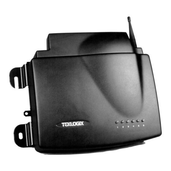
(access point) between wireless and wired networks. This allows wireless clients to access the network and also move seamlessly between the 9150s in the network. The 9150 can also operate as a Teklogix base station or a mini-controller. - Page 19 Chapter 1: Introduction About The 9150 .igure 1.1 The 9150 Wireless Gateway - .ront View .igure 1.2 The 9150 Wireless Gateway - Bottom View Teklogix 9150 Wireless Gateway User Manual...
-
Page 20: Base Station Functions
Base Station Functions 1.3.1 Base Station .unctions As a base station, the 9150 provides a link between the local area network and the wireless network consisting of Teklogix mobile terminals, and base stations such as the 9140 Wireless Gateway. The 9150 and 9400/9300 Network Controller (or host using a Teklogix Software Development Kit) communicate using the 9010 propri- etary protocol with TCP/IP over Ethernet, Token Ring or serial connectivity. -
Page 21: Radio Options
Radio Options 1.4 Radio Options The 9150 supports Type II PCMCIA cards so that multiple radio interfaces are possible. There is one internal and one external PC card slot available. The type of PCMCIA radio card installed in the 9150 is dependent on your wireless network. Currently supported radios are: •... -
Page 22: Adaptive Polling/Contention Protocol
If a “collision” occurs – more than one terminal attempts to respond in a particular window – the 9150 that is polling divides and reassigns that group until the colliding terminals can respond without a collision. - Page 23 Note: For detailed information on configuring the 9150 as a base station, please see Chapter 4: “Base Station Configuration”. For a generalized system diagram, see Figure 1.3, below.
-
Page 24: Ieee 802.11 Protocol
Using bridging software, the 9150 Wireless Gateway enables communication between any wireless IEEE 802.11-equipped stations and LAN stations operating on Ethernet or Token Ring. The 9150 itself is resident on the LAN and functions as a MAC bridge, providing transparent integration between the stations on the wire- less and wired networks. -
Page 25: Inter-Access Point Protocol (Iapp)
In a multiple-9150 system, IAPP informs the other 9150 Wireless Gateways when a new 9150 becomes active, and enables the awareness of the 9150s of each other. With IAPP, an IEEE 802.11 system can operate on one or more channels, with terminals moving between the 9150s. - Page 26 IEEE 802.11 Protocol 7040 Hand-Held R. Terminal HOST 7035 Hand-Held R. Terminal 9150 Wireless Gateway 7040 Hand-Held R. Terminal 9400 Network Controller 9150 Wireless Gateway 7035 Hand-Held R. Terminal .igure 1.4 9150 Access Point Configuration Teklogix 9150 Wireless Gateway User Manual...
- Page 27 2.2.4 Preparing For Serial Installation ... 20 2.2.5 Connecting A Video Display Terminal ..21 2.3 Changing The Configuration With A Web Browser ..21 Teklogix 9150 Wireless Gateway User Manual...
-
Page 29: Chapter 2: Installation Requirements
The 9150 should only be mounted in the upright position, as shown in Figure 2.1, below. This orientation minimizes the risk of water entering the 9150, should the unit accidentally be sprayed. -
Page 30: Maintenance
30 cm of the unit. Secure the cables with ties to the cable tie mounts on the 9150 (see Figure 2.1 on page 15). A single phase power outlet (range 100 to 240 VAC rated 1.0A minimum) should be installed within one metre (3.1 feet) of the 9150. -
Page 31: Connecting To External Devices
9150. The coaxial cable must be routed and secured using wire anchors and/or coaxial nail clips. A few extra inches of cable are required near the antenna and the 9150 to make disconnection easier. 2.2 Connecting To External Devices... -
Page 32: Status Indicators (Leds)
Once the 9150 is installed, connected and powered on, the system administrator can access the unit to check the configuration and to assign the 9150 its unique IP address. This may be done through the Console port or through the network (see “Connecting A Video Display Terminal”... -
Page 33: Ethernet
Since these ports are auto-selecting, jumper or configuration settings are not required. The maximum packet size sup- ported over the network is 1500 bytes. This parameter is not set at the 9150, but should be set at the host. -
Page 34: Preparing For Serial Installation
The type of data cable used depends on the type of port required at the site. The type of port depends on the location of the 9150 and whether it is to be connected to a host computer or a network controller. Modems can be used to better accommodate long distances between the 9150 and the host computer or network controller. -
Page 35: Connecting A Video Display Terminal
An ANSI compatible video display terminal (e.g., DEC VT220 or higher), or a PC running terminal emulation, is used for diagnostic purposes and to configure the IP address for the first time before the 9150 can be accessed using a Web Browser (see “Configuring The IP Address” on page 25). - Page 37 3.6.1 System Info ..... 42 3.6.2 Reboot Unit ..... 43 Teklogix 9150 Wireless Gateway User Manual...
-
Page 39: Configuration Main Menu
VT220 or higher. Cable no. 19387 should be used to connect the PC to the 9150. Make sure the communications settings on your PC are set to 8 bits, 1 stop, no parity, and that the baud rate of the serial port matches that of the 9150 console port (19,200 baud). - Page 40 To display the default gateway: >cfg get system.defaultgateway To configure the default gateway: >cfg put system.defaultgateway xxx.xxx.xxx.xxx To display the default subnetmask: >cfg get interface.1.defaultsubnetmask To configure the default subnetmask: >cfg put interface.1.defaultsubnetmask xxx.xxx.xxx.xxx Teklogix 9150 Wireless Gateway User Manual...
-
Page 41: Accessing The Menus
Accessing The Menus 3.3 Accessing The Menus When the Web Browser is pointed to the 9150’s IP address, a name and password dialog box appears. The password is comprised of alphanumeric characters and is case-sensitive. If you change the password (see “Users” on page 34), set all 9150s to the same password, and write it down in a secure place. - Page 42 Chapter 3: 9150 Main Configuration Accessing The Menus .igure 3.1 9150 Configuration Main Menu: View .rom Browser Teklogix 9150 Wireless Gateway User Manual...
-
Page 43: General Configuration Options
3.4 General Configuration Options The General Configuration menu on the Configuration Main Menu page presents five options of sub-menus: Interfaces , Users, SNMP, TCP/IP Parameters, and Serial Ports Parameters. .igure 3.2 Overview Of General Configuration Menus Teklogix 9150 Wireless Gateway User Manual... -
Page 44: Interfaces
(hardware) address and IP address parameters. Physical Address A unique Physical Address is assigned by Teklogix personnel for each 9150. The values entered for this parameter are presented in hexadecimal in descending order beginning with the MSB (Most Significant Byte), the highest value, and ending with the LSB (Least Significant Byte), the lowest value. - Page 45 Chapter 3: 9150 Main Configuration Interfaces IP Parameters Each 9150 that is connected to a local network has a unique IP address designated for it. The IP Parameters used to assign the IP address are accessed by entering the “Configure” dialog box.
-
Page 46: Slot N: Token-Ring
(hardware) address, ring speed, and IP address parameters. Physical Address Each Madge Token Ring PC card has a unique MAC address (Physical Address), which is displayed here in the 9150 parameters. The MAC address is presented in standard hexadecimal format. Ring Speed This parameter indicates the Token Ring network speed. - Page 47 Chapter 3: 9150 Main Configuration Interfaces IP Parameters Each 9150 that is connected to a local network has a unique IP address designated for it. The IP Parameters used to assign the IP address are accessed by entering the “Configure” dialog box.
-
Page 48: Slot N: Pc Card Radio
3.4.1.3 Slot n: PC Card Radio Each PC (PCMCIA) card radio resident in the 9150 will be located in one of two Slots: A or B. Selecting a PC card will open the sub-menu for that radio. IEEE 802.11 FH or DS: See “IEEE 802.11 (Frequency Hopping Radio Parame- ters)”... -
Page 49: Snmp
Chapter 3: 9150 Main Configuration SNMP 3.4.3 SNMP The SNMP (Simple Network Management Protocol) “Configure” page allows various network management parameters to be set or changed. Teklogix 9150 Wireless Gateway User Manual... -
Page 50: System Parameters
Trap Receivers These IP addresses determine which SNMP manager’s stations will receive SNMP Traps from the 9150. The 9150 sends the “Cold Start” Trap on reboot or power up. 3.4.4 TCP/IP Parameters The 9150 is situated on a wired network which uses TCP/IP. Both Bootp and DNS options are available to resolve IP addressing issues. -
Page 51: Host Table
3.4.4.1 Host Table If no external DNS server is available, the 9150 may resolve host names to IP addresses using its internal host table. Hosts are added to the table by selecting “Configure” beside “[#} Add Entry” in the listbox. This will open the New Host Table Entry menu. -
Page 52: Bootp
The 9150 has designated default IP addresses for itself and the Gateway. Alterna- tively, the IP address of the 9150 can be assigned using a BOOTP Server. The primary purpose of the Bootstrap Protocol (BOOTP) is to assign a designated IP address to the appropriate 9150 on the network. -
Page 53: Dns
The Default Gateway Address is assigned by the network administrator. This address creates an identifiable communication link between the 9150 and a network other than the one to which the 9150 is directly wired. The acceptable values for the Gateway IP address range from 0.0.0.0 to 239.255.255.255. -
Page 54: Serial Ports Parameters
Chapter 3: 9150 Main Configuration Serial Ports Parameters 3.4.5 Serial Ports Parameters 3.4.5.1 Console Port The default baud rate for the console port is 19.2k. 3.4.5.2 Serial Port The default baud rate for the serial port is 19.2k. Teklogix 9150 Wireless Gateway User Manual... -
Page 55: Access Point/Base Station Configurations
For these operations, the parameters in these pages must be set appropriately. For detailed information on the sub-menus and to set up the 9150 as a base station, see Chapter 4: “Base Station Configuration”. To configure an access point device, see Chapter 6: “Access Point Configuration”. -
Page 56: Miscellaneous Commands
There are two miscellaneous commands: System Info and Reboot Unit. 3.6.1 System Info The System Information, hardware and software, for the 9150 Wireless Gateway unit is detected automatically and summarized in this page. The screen is shown on page 43. -
Page 57: Reboot Unit
This option opens a dialog box which allows you to remotely “warm” reboot the 9150. If the OK button is chosen, the 9150 will be rebooted, the LEDs will turn off momentarily, and the following message will be received: Important:... - Page 59 4.5 Base Stations ......71 4.6 Radio Link Features ......72 Teklogix 9150 Wireless Gateway User Manual...
-
Page 61: Overview
Alternatively, the network controller can be a host running a Teklogix SDK (handler). The 9150 can also act as a slave base station to a 9140 on the network. As a base station, the 9150 uses the Wireless LAN (Wlan) or Adaptive Polling/Contention RF protocols. - Page 62 In addition, the appropriate radio parameters must be applied. These are found in the Interfaces pages for TekLAN and Narrow Band radios. See pages 49and 53, respectively. .igure 4.2 Overview Of Base Station Configuration Menus Teklogix 9150 Wireless Gateway User Manual...
-
Page 63: Interfaces
4.2 Interfaces 4.2.1 TekLAN Parameters The pull-down menu shown for the Interfaces option in the 9150 Configuration Main Menu page indicates which interfaces have been detected in use. Entering the “Configure” dialog box for “Slot A: TekLAN Card”, opens the parameters page for TekLAN, which presents both the radio and Wlan parameters. -
Page 64: Radio
Radio Radio Type The type of PC radio card installed on the 9150 is dependent on your wireless net- work. This parameter should be set to the installed radio. The radios for TekLAN are the TekLAN 902 MHz DS Spread Spectrum, and the TekLAN 2.4 GHz DS Spread Spectrum. - Page 65 ) polling immediately when the 9150 is rebooted. If Auto Startup is disabled, the 9150 will wait until polling is initialized from the network controller. When the 9150 is operating as a Wlan base station under a network con- troller, this parameter should be disabled.
-
Page 66: Wireless Lan Parameters
This parameter is used to assign a unique address to each base station. As the termi- nals move from one base station to another, this address is transmitted by the base stations to the terminals, identifying each 9150 on a multiple base station system. The allowable range of base station numbers is 1 to 64. -
Page 67: Narrow Band Radio Parameters
This parameter determines the time in minutes that a terminal is allowed to be inac- tive before the 9150 declares it offline. An offline terminal is still considered part of the system. Messages to offline terminals are queued at the 9150. The terminal remains offline until it transmits any message. - Page 68 Chapter 4: Base Station Configuration Narrow Band Radio Parameters .igure 4.4 Overview Of Teklogix Narrow Band Menus Teklogix 9150 Wireless Gateway User Manual...
- Page 69 √ This parameter enables ( ) polling immediately when the 9150 is rebooted. If Auto Startup is disabled, the 9150 will wait until polling is initialized from the network controller. Shared Channel Shared Channel is only used in Holland to accommodate government requirements.
-
Page 70: Polling Protocol Parameters
4.2.2.1 Polling Protocol Parameters Number of Poll Windows This parameter defines the number of poll windows the 9150 will use. The value assigned to this parameter is dependent on the number of terminals and the radio link protocol used. Table 4.2 indicates how the value assigned to the Number of Poll Windows parame- ter is determined. - Page 71 This parameter determines the largest single message that can be passed to a terminal in message mode or from a terminal in long message mode. In a 9150 base station, the value entered in this parameter must be greater than or equal to the value entered in the network controller or 9150 mini-controller.
- Page 72 Callsign String This string can be a maximum of 10 characters long. All characters are either numbers or letters. The prefix “DE” (from) is added to the beginning of the transmit- ted call sign. Teklogix 9150 Wireless Gateway User Manual...
-
Page 73: Radio Parameters
The value assigned to the Remote Txon parameter must be consistent across all terminals and base station equipment. Important: This parameter should not be changed from its factory setting without an understanding of the timing of the radio protocol. Teklogix 9150 Wireless Gateway User Manual... -
Page 74: Radio Channels
Narrow Band Radio Parameters 4.2.2.3 Radio Channels Active Channel This parameter determines the operating radio channel of the 9150. The channel selected must be an enabled channel. Refer to Enabled Channels, below, for details. Enabled Channels √ This parameter is used to enable ( ) or disable up to 20 channels –... - Page 75 Chapter 4: Base Station Configuration Narrow Band Radio Parameters Teklogix 9150 Wireless Gateway User Manual...
-
Page 76: General Parameters
Chapter 4: Base Station Configuration Narrow Band Radio Parameters General Parameters .requencies Teklogix 9150 Wireless Gateway User Manual... -
Page 77: Hosts
A “host” must be configured for each master network controller, TSDK host, or master base station that communicates with the 9150. Opening the “Configure” dialog box for a selected host lists the parameters that can be modified or deleted for that host. - Page 78 • ANSI/Telnet (See pages 113 to 121 for Configuration Parameters). When the 9150 acts as a base station, it uses the 9010 protocol (a proprietary protocol developed by Teklogix) with either a TCP/IP or serial connection to com- municate with a 9400 or 9300 Network Controller, or a host using a Teklogix Software Development Kit (TSDK).
-
Page 79: Main Host Menu
4.4 Main Host Menu When you choose an existing host from the Hosts listbox and then select the Config- ure button, the 9150 displays the Host Menu. .igure 4.5 Overview Of Host Menus .or 9010 / TCP/IP Teklogix 9150 Wireless Gateway User Manual... -
Page 80: General Host Options
This page may vary depending on the type of emulation and protocol selected for the host. There is also a Main Menu button. When you select this button, the 9150 displays the Configuration Main Menu (see page 48). -
Page 81: 9010 / Tcp/Ip
This parameter allows you to select the emulation and protocol to be used for the connection to this host. As a base station, the 9150 can use either 9010/ TCP/IP or 9010/SERIAL, depending on the connection to the network controller or host. -
Page 82: 9010 / Serial
9010 / Serial 4.4.2.2 Protocol Options And .unction Key Mappings These parameters are not applicable to the 9010 / TCP/IP emulation. 4.4.3 9010 / Serial .igure 4.6 Overview Of Host Menus .or 9010 / Serial Teklogix 9150 Wireless Gateway User Manual... -
Page 83: Emulation Options
), the 9150 base station does not notify the host if the status of a terminal changes between offline and online. If this parameter is disabled, the 9150 does notify the host regarding any terminal status changes. 4.4.3.2 Protocol Options: Serial Line Line Protocol This listbox specifies the serial line protocol used on this host connection. -
Page 84: Protocol Options: 9010 Protocol
The default setting is STX/ETB. Use Cyclic Redundancy Check (CRC) √ If this parameter is enabled ( ), the 9150 base station uses a CRC checksum on the data sent over the serial line to the host. 4.4.3.3 Protocol Options: 9010 Protocol Use NS/NR √... -
Page 85: Base Stations
These options and parameters allow you to configure the 9150 as a master base station connected to up to 32 slave 9150 and 9140 base stations over an Ethernet or Token Ring network. The master 9150 is connected to a 9400 or 9300 Network Controller, or up to six hosts running TSDK (Teklogix Software Development Kit). -
Page 86: Radio Link Features
When this parameter is enabled ( ), the slave base stations will start polling when the master 9150 boots up. When Auto-Startup is disabled, the base stations will not start polling until they receive a start polling command from the host. - Page 87 Radio Link Features Poll ID In Wlan protocol, this is a unique identifying number set only in a 9150 master base station, 9150 mini-controller or a network controller, which is used in the poll header when polling terminals. Poll ID is set by Teklogix personnel.
- Page 89 5.3.5.2 Protocol Options ....116 5.3.5.3 Function Key Mappings ... 121 Teklogix 9150 Wireless Gateway User Manual...
-
Page 91: Chapter 5: Mini-Controller Configuration
The 9150 is equipped with emulation capabilities, allowing it to act as a mini- controller. When a 9150 is configured as a mini-controller, Teklogix terminals can emulate an ANSI, 5250 or 3274 terminal via a 9150 rather than through a 9400/9300 Network Controller. - Page 92 9140 Wireless Gateway 8055 Vehicle-Mount R. Terminal 9150 Wireless Gateway Mini-Controller ETHERNET TCP/IP 7035 9150 Wireless Gateway 7030 Hand-Held Hand-Held Base Station and Access Point R. Terminal R. Terminal .igure 5.1 9150 Mini-Controller Configuration Teklogix 9150 Wireless Gateway User Manual...
- Page 93 For operation as a mini-controller, the parameters in the Hosts pages under Base Station Configuration should be set appropriately. The Hosts options are found on the Configuration Main Menu page. For information on configuring radio protocol parameters, please refer to “Radio Link Features” on page 72. Teklogix 9150 Wireless Gateway User Manual...
-
Page 94: Hosts
Emulation and Protocol This drop-down menu provides a list of host emulations and communication proto- cols supported by the 9150. Working with Teklogix terminals and base stations, the 9150 can emulate IBM 3278-2, 5251-11, and 5555-B01 terminals, as well as ANSI terminals. - Page 95 • ANSI/Telnet (See pages 113 to 121 for Configuration Parameters). When the 9150 acts as a base station, it uses the 9010 emulation (a proprietary asyn- chronous protocol developed by Teklogix) to communicate with a 9300 Network Controller or a host using a Teklogix Software Development Kit (TSDK). For detailed information on configuring the 9150 as a base station, please refer to Chapter 4: “Base Station Configuration”.
-
Page 96: Main Host Menu
5.3 Main Host Menu When you choose an existing host name from the Hosts listbox and then select the Configure button, the 9150 displays the Host Menu. The Host Menu presents the options for four sub-menus: General Host Options, Emulation Options, Protocol Options, and Function Key Mappings. -
Page 97: General Options
As illustrated in Figure 5.2 on page 82, the four configuration sub-menus display the following options: “General Options” When you select this sub-menu, the 9150 displays the General Options page for the host. “Emulation Options” When you select this sub-menu, the 9150 displays the Emulation Options page for the host. -
Page 98: 9010 Emulations
Terminal numbers may range from 1 to 50. 5.3.2 9010 Emulations When the 9150 acts as a base station, it uses the 9010 protocol (a proprietary asyn- chronous protocol developed by Teklogix) to communicate with a 9400 or 9300 Network Controller, or a host using a Teklogix Software Development Kit (TSDK). - Page 99 Chapter 5: Mini-Controller Configuration 3274/Telnet Emulation Options Teklogix 9150 Wireless Gateway User Manual...
- Page 100 Passthru If this parameter is enabled, the 9150 allows the host to send data directly to the RF terminal’s serial port. This is most commonly used for printing. Teklogix 9150 Wireless Gateway User Manual...
- Page 101 1 2 3 4 5 where @ is an attribute. When the 9150 is finished sending the data to the terminal’s printer, it will send an ENTER key to the host. The host must wait for the ENTER key before sending any more screens (including other PASSTHRU screens) to this terminal.
- Page 102 The text that is passed to the printer is formatted into the 24 x 80 application screen. If the host can initiate the print operation, the text is printed. The 9150 identifies the additional text as a print page by the presence of the word “PRINT” (in capital let- ters) beginning in the 2nd column of line 13 on the 24 x 80 screen.
- Page 103 The 9150 reduces data transmitted to the terminals by using the terminal’s capability to store a page of data for each screen it displays. The 9150 maintains an image of each page stored at the terminal. After receiving an application screen, the 9150 tries to match the screen with a stored page.
- Page 104 “AIAG” field by the application program determines whether or not the bar code data is accepted. At the 9150 mini-controller, a decimal value of an ASCII character from 0 to 127 is set to match the “AIAG Field Identifier” set at the host. A value of 0 disables this feature.
- Page 105 Mode 0, and finally, the “AIAG Prefix” – I. AIAG Information .rom Host AIAG Field Identifier AIAG Prefix (data) Item No. Mode .igure 5.4 AIAG .ield Sent .rom The Host Teklogix 9150 Wireless Gateway User Manual...
- Page 106 ASCII characters. A value of 0 disables this feature. The ASCII decimal value entered at the 9150 must coincide with the value set by the application program. To use the Visible Match feature, the host computer preloads data into a match entry field;...
- Page 107 The range for this parameter – 0 to 127 – represents the decimal values of ASCII characters. A value of 0 disables this feature. The ASCII decimal value entered at the 9150 must coincide with the value set by the application program. Teklogix 9150 Wireless Gateway User Manual...
- Page 108 Normally, Teklogix terminals only display the upper-left corner of the application screen because of their smaller display size. Teklogix 9150 Wireless Gateway User Manual...
-
Page 109: Protocol Options
This parameter contains the maximum number of characters allowed between two fixed fields which still allows the 9150 to join them into one field. Sometimes the 9150 will join two adjacent fixed fields and then send them as one field. This reduces the overhead on the radio link. - Page 110 3274/Telnet Protocol Options Terminal Type This parameter allows you to choose the type of terminal to be emulated by the 9150 for this host. At present there is only one choice of terminal for 3274/Telnet: the IBM 3278-2. Host Port This parameter allows you to enter a host port value for the selected 3274/Telnet host connection.
- Page 111 If this parameter is enabled, the 9150 sends the IAC Interrupt Process request to the host as a 3274 System Request. Send IAC Break as an Attention Key If this parameter is enabled, the 9150 sends the IAC Break request to the host as a 3274 Attention key. Teklogix 9150 Wireless Gateway User Manual...
-
Page 112: Function Key Mappings
.unction Key Mappings This page differs depending on the type of emulation selected in the General Host Options page. The 9150 displays this version of the Function Key Mapping page when you select 3274 emulation for this host. .unction key n The Function Key parameter allows you to select a code that will be sent to the host when you press a function key on the terminal. -
Page 113: 5250/Telnet
Chapter 5: Mini-Controller Configuration 5250/Telnet Emulation Options 5.3.4 5250/Telnet 5.3.4.1 Emulation Options Teklogix 9150 Wireless Gateway User Manual... - Page 114 If screen text is chosen, the 9150 sends the error codes as regular screen text. Use International EBCDIC If this parameter is enabled, the 9150 will swap the positions of the ! and ] charac- ters in the EBCDIC character table. Alarm If this parameter is enabled, terminals will beep when the word “ALARM”...
- Page 115 Note: This operation is only performed on screens received from the host. Data sent to the host remains unaffected. Passthru If this parameter is enabled, the 9150 allows the host to send data directly to the RF terminal’s serial port. This is most commonly used for printing. Preparing Host Screens for Pass-Through On the screen to be sent through the terminal serial port, the word “PASSTHRU”...
- Page 116 TESS execute procedure command. Local If this parameter is enabled, the 9150 allows the host to provide pages to be loaded as local TESS procedures in the terminals. The local procedures are selected from a menu at the terminal. The terminals can perform these procedures when they are offline.
- Page 117 7030/8055/8060 Terminals User Manual for more information. Remote Print When this parameter is enabled, the 9150 sends the print page to a terminal when- ever the terminal requests it (by sending the “F17” function key from the terminal, or the “PRINT” key on older terminals). The 9150 sends the function response back to the host.
- Page 118 The 9150 reduces data transmitted to the terminals by using the terminal’s capability to store a page of data for each screen it displays. The 9150 maintains an image of each page stored at the terminal. After receiving an application screen, the 9150 tries to match the screen with a stored page.
- Page 119 Add 16 to above values to indicate cursor position priority for search and fill. AIAG Prefix (data) The text to be matched in the AIAG field. Table 5.3 Mode .unctions And AIAG Prefix Description Teklogix 9150 Wireless Gateway User Manual...
- Page 120 “match field” from an entry field. For example, suppose an angle bracket “ ” is defined for visible match fields. Inserting “ ” immediately > > preceding the entry field identifies it as a match field, as illustrated below. Part #> ___________ Teklogix 9150 Wireless Gateway User Manual...
- Page 121 ASCII characters. A value of 0 disables this feature. The ASCII decimal value entered at the 9150 must coincide with the value set by the application program. To use the Visible Match feature, the host computer preloads data into a match entry field;...
- Page 122 The range for this parameter – 0 to 127 – represents the decimal values of ASCII characters. A value of 0 disables this feature. The ASCII decimal value entered at the 9150 must coincide with the value set by the application program. Serial I/O Serial I/O fields are special entry and fixed fields that accept input from and output to a serial port.
- Page 123 This parameter contains the maximum number of characters allowed between two fixed fields which still allows the 9150 to join them into one field. Sometimes the 9150 will join two adjacent fixed fields and then send them as one field. This reduces the overhead on the radio link.
-
Page 124: Protocol Options
5250/Telnet for this host. Terminal Type This parameter allows you to choose the type of terminal to be emulated by the 9150 for this host. At present there are two choices of terminal for 5250/Telnet: the IBM 5251-11 and IBM 5555-B01. - Page 125 .irst Terminal Listen Port This parameter specifies the first port number at which the 9150 will listen for telnet connection requests to the terminals. The default value is 0. Actively Negotiate with Host If this parameter is enabled, the 9150 negotiates with the host during setup of the telnet connection.
-
Page 126: Function Key Mappings
.unction Key Mappings This page differs depending on the type of emulation selected in the General Host Options page. The 9150 displays this version of the Function Key Mapping page when you select 5250 emulation for this host. .unction key n The Function Key parameter allows you to select a code that will be sent to the host when you press a function key on the terminal. -
Page 127: Ansi/Telnet
The range is 0 to 255, with a default value of 15. If the 9150 does not receive any characters from the host after this timeout has elapsed, it assumes that the host has finished sending data and is waiting for user input (in other words, it assumes that a screen of data has been completed). - Page 128 The Threshold is the minimum number of bytes of update data for the terminal screen which must be received from the host before the 9150 will store the screen as a new “saved page”. The range is 0 to 999, with a default value of 200.
- Page 129 9150 instructs the terminal to redisplay its stored copy of the page; no data need be sent across the radio link for that page. If the 9150 finds no match for the page, the complete page is sent to the terminal.
-
Page 130: Protocol Options
Protocol Options This page differs depending on the type of emulation and protocol selected in the General Host Options page. The 9150 displays this version of the Protocol Options page when you select the emulation/protocol combination of ANSI/Telnet for this host. - Page 131 ANSI/Telnet Protocol Options Terminal Type This parameter specifies the type of terminal to be emulated by the 9150, either a VT100 or VT200. Host Port This parameter specifies the value for the host port for the selected ANSI host con- nection.
- Page 132 When Auto-telnet is disabled, telnet sessions from the terminals to the host must be initiated manually from the terminals. When Auto-telnet is enabled, the 9150 initiates one telnet session from each termi- nal whose terminal number is mapped to this host. Additional telnet sessions may be initiated from each terminal to the host, but they must be initiated manually.
- Page 133 15 characters. Auto-login User ID prompt The 9150 compares the text in this textbox to the text presented to it by the host. When they match, the 9150 assumes that the host has just sent its request for a user name, and it sends the user ID specified in the Auto-Login User ID parameter to the host.
- Page 134 Protocol Options Auto-login Password prompt The 9150 compares the text in this textbox to the text presented to it by the host. When they match, the 9150 assumes that the host has just sent its request for a pass- word, and it sends the password specified in the Auto-Login Password parameter to the host.
-
Page 135: Function Key Mappings
.unction Key Mappings This page differs depending on the type of emulation selected in the General Host Options page. The 9150 displays this version of the Function Key Mapping page after you have selected the ANSI/Telnet emulation/protocol combination for this host connection. - Page 136 Each function key may be chosen from the same range of possible codes; however, each function key has a different default code. The default values are shown on the screen on page 121. Teklogix 9150 Wireless Gateway User Manual...
- Page 137 6.4 Mobility Configuration ..... . 140 6.4.1 IAPP Parameters ....142 Teklogix 9150 Wireless Gateway User Manual...
-
Page 139: Chapter 6: Access Point Configuration
IEEE 802.11, please refer to “IEEE 802.11 Protocol” on page 10. For operation as an access point, the parameters in the following pages must be set appropriately. Note: The 9150 main parameters should first be set up as described in Chapter 3: “9150 Main Configuration”. 7040 Hand-Held R. -
Page 140: Interfaces
Interfaces 6.2 Interfaces The pull-down menu shown for the Interfaces option indicates which interfaces have been detected in use by the 9150, including one of two 802.11 PCMCIA radios: • IEEE 802.11 FH: Proxim RangeLAN802 IEEE 802.11 FHSS 2.4 GHz. - Page 141 Hopping Set The combined settings for the Hopping Set and Hopping Pattern parameters deter- mine the operating channel for a radio using frequency hopping. Please refer to your system administrator for details. Teklogix 9150 Wireless Gateway User Manual...
-
Page 142: Ieee 802.11 (Direct Sequence Radio Parameters)
6.2.2 IEEE 802.11 (Direct Sequence Radio Parameters) When the Lucent WaveLAN IEEE 802.11 DSSS 2.4 GHz PCMCIA card is installed in the 9150, the following radio parameters page is opened: Physical Address This parameter shows the hardware address (MAC address) of the radio card. -
Page 143: Mac Bridge Parameters
The MAC Bridge parameters consist of protocol filters which direct the 9150 to forward or discard frames that contain a known protocol type. This enables the 9150 to be selective of what type of frames will be bridged over the radio, in order to limit the amount of data on busy networks. - Page 144 Figure 6.2 below charts the pages for the MAC bridge filters. Entering “OK” or “Cancel” in the individual Filter pages will return you to the Bridge Parameters page. .igure 6.2 Overview Of MAC Bridge Configuration Menus Teklogix 9150 Wireless Gateway User Manual...
-
Page 145: General Configuration
√ filtering is enabled ( ), the 9150 can filter out frames based on destination MAC addresses. The list of MAC addresses for filtering is set by the Address Filters option on page 132. Frames are filtered and either forwarded or discarded, depending on the rest of the settings in this configuration. -
Page 146: Address Filters: Mac Address
6.3.2 Address .ilters: MAC Address The 9150 can use a list of destination MAC addresses to filter out frames. The MAC addresses are those of any terminals associating with the 9150. If Address Filters on page 131 is enabled, then any frame destined for any address in the list will be for- warded. -
Page 147: Protocol Filters
Protocol Filters 6.3.3 Protocol .ilters When the 9150 receives frames, it can forward or discard the messages by filtering the protocol Type fields encapsulated in the frame. The filtering is done on three types of Ethernet headers: Ethernet II, LLC and SNAP. - Page 148 The listboxes in the Protocol Filters option show the protocol filters already set in the configuration database. Selecting a protocol name and then opening the “Config- ure” dialog box gives a list of parameter settings that can be modified or deleted for that protocol. Teklogix 9150 Wireless Gateway User Manual...
- Page 149 Chapter 6: Access Point Configuration Protocol Filters .igure 6.4 Protocol .ilters Main Menu And Sub-menus New filters can be added by selecting “[#] Create New” in the listbox before enter- ing the “Configure” dialog box. Teklogix 9150 Wireless Gateway User Manual...
-
Page 150: Ethernet Ii Filters
Name This is any name you wish to use to describe this Ethernet II filter. Action This parameter can be set to either forward or discard frames with protocol types that match this filter. Teklogix 9150 Wireless Gateway User Manual... -
Page 151: Llc Filters
(DSAP/SSAP) parameter must be a four-digit hexadecimal number ranging from 0 to 0xFFFF, where the first pair of digits is the DSAP and the last pair is the SSAP. For a listing of DSAP/SSAP types, see “DSAP/SSAP Types” on page B-14. Teklogix 9150 Wireless Gateway User Manual... -
Page 152: Snap Filters
0 to 0xFFFF, which represents the SNAP type you wish to filter. √ When this parameter is enabled ( ), this Type will be filtered. For a short listing of OUI values, see “OUI Values” on page B-15. Teklogix 9150 Wireless Gateway User Manual... -
Page 153: Storm Detection
The broadcast storm is determined to be over when the number of broadcast frames received for a one second period is less than or equal to the value entered in this parameter. Setting the value for Restart is determined by the characteristics of your network. Teklogix 9150 Wireless Gateway User Manual... -
Page 154: Mobility Configuration
Chapter 6: Access Point Configuration Mobility Configuration 6.4 Mobility Configuration The Mobility Configuration page is entered from the Access Point Configuration menu on the first page. Going to the Mobility Configuration page opens the IAPP Parameters options. Teklogix 9150 Wireless Gateway User Manual... - Page 155 In a multiple-9150 system, IAPP facilitates roaming of mobile stations among the 9150s, and enables communication and awareness between the 9150s. Every termi- nal is associated with one 9150, but it can reassociate with another 9150 to maintain uninterrupted communications. The association is “handed over” from one 9150 to the next.
-
Page 156: Iapp Parameters
140. Handover Timeout If there is no response to the Handover request by the 9150 within the time specified in the Handover Timeout parameter, the request is retransmitted. If no response is received after a number of retries (set in the Handover Retries parameter, below), the 9150 will complete the reassociation procedure itself. - Page 157 PECIFICATIONS 7.1 Specifications For The 9150 Wireless Gateway ..145 7.1.1 PC Card Radios ....145 7.1.2 Power Requirements .
-
Page 159: Chapter 7: Specifications
Chapter 7: Specifications Specifications For The 9150 Wireless Gateway Note: Performance specifications are nominal and subject to change without notice. 7.1 Specifications For The 9150 Wireless Gateway 7.1.1 PC Card Radios Important: For sites in Canada, Lucent WaveLAN 802.11 and Proxim Range- LAN 802.11 radios require a radio licence, unless they are installed... - Page 160 2.4 to 2.4835 GHz Data Rate 11 Mbps No. of Channels 11 (FCC) 13 (ETSI) 4 (FR) 1 (JP) 2 (SP) * For regulatory information concerning the Lucent WaveLAN PC Card, please see page 149. Teklogix 9150 Wireless Gateway User Manual...
-
Page 161: Power Requirements
-40°C to 70°C (-40°F to 158°F) Dust and Rain IEC 529 IP42 7.1.6 Network Interfaces On-Board Ethernet 10Base5 10Base2 10Base-T Token Ring Madge Token Ring Smart 16/4 Ringnode Adapter Type II PC card, 4 or 16 Mbps Teklogix 9150 Wireless Gateway User Manual... -
Page 162: Slim Cards
RS-232/20 mA Current Loop Optically isolated RS-232 Plus 7.1.8 Approvals FCC Part 15, subpart B, Class B Electrical Safety: CSA/NRTL, TÜV, CB Scheme CE Mark ETS 300 113 ETS 300 086 ETS 300 220 ETS 300 328 Teklogix 9150 Wireless Gateway User Manual... - Page 163 RF exposure compliance. Refer to the Regulatory State- ments as identified in the documentation that comes with those products additional information. Teklogix 9150 Wireless Gateway User Manual...
- Page 164 The correction of interference caused by such unauthorized modification, substitu- tion or attachment will be the responsibility of the user. For country-specific approvals, please consult the flyer “Radio Certification Infor- mation” that is included with the 9150 Wireless Gateway. Teklogix 9150 Wireless Gateway User Manual...
-
Page 165: Console Port
Signal Ground – Data Terminal Ready Request to Send * always pulled high A.2 RS-232 Plus Port (SLIM Card) Pin No. Name .unction Direction Frame Ground – Transmit Data Receive Data Signal Ground – Teklogix 9150 Wireless Gateway User Manual... -
Page 166: Rs-232/Current Loop Port (Slim Card
Request to Send Clear to Send Data Set Ready Signal Ground – Data Carrier Detect – 20 mA Current Loop – 20 mA Current Loop – 20 mA Out – Loop Enable Data Terminal Ready Teklogix 9150 Wireless Gateway User Manual... -
Page 167: Da15 Connector Pinout (10Base5 Ethernet
Transmit + Signal Ground – Receive + Signal Ground – No Connection – Signal Ground – Collision - Transmit - Signal Ground – Receive - +12 Volt Supply Signal Ground – No Connection – Teklogix 9150 Wireless Gateway User Manual... -
Page 168: Connector Pinouts (10Base-T Ethernet
A.5 RJ-45 Connector Pinouts (10Base-T Ethernet) Contact Signal TD – Not used Not used RD – Not used Not used Note: Usually, a straight-through connection is needed to connect Twisted-Pair (10Base-T) to the hub. Teklogix 9150 Wireless Gateway User Manual... -
Page 169: Token Ring Dsub9 Connector
+5 Volt Supply Frame Ground – Ring Output (B) Ring Input (B) Frame Ground – Frame Ground – Ring Output (A) * This connection supports Shielded Twisted Pair (IBM STP) cable Type 1 or 6. Teklogix 9150 Wireless Gateway User Manual... -
Page 170: Serial Cable Descriptions
Direct RS-232 16590 15 feet 9400/9300 to 9150 Modem RS-232 16598 8 feet 9400/9300 to 9150 Current Loop 16599 15 feet 9150 to Console Direct 19387 6 feet DTE to DTE Cable No. 16590 Teklogix 9150 Wireless Gateway User Manual... - Page 171 Appendix A: Port Pinouts And Cable Diagrams Serial Cable Descriptions DTE to DCE Cable No. 16598 Current Loop Cable No. 16599 Teklogix 9150 Wireless Gateway User Manual...
- Page 172 Appendix A: Port Pinouts And Cable Diagrams Serial Cable Descriptions Console Port Cable No. 19387 Teklogix 9150 Wireless Gateway User Manual...
-
Page 173: Ethernet Ii Types (Rfc 1700
0x8036 Allen-Bradley 0x80E0-0x80E3 Alpha Micro 0x814A Apollo Computer 0x80F7 Apollo Computers 0x8019 Appletalk 0x809B AppleTalk AARP (Kinetics) 0x80F3 Applitek Corporation 0x80C7 Apricot Computers 0x81CC-0x81D5 ARAI Bunkichi 0x81A4 0x0806 Artisoft 0x81D6-0x81DD Ascom Banking Systems 0x8221-0x8222 Teklogix 9150 Wireless Gateway User Manual... - Page 174 Bridge Communications 0x8132-0x8136 Cabletron 0x7034 Chaosnet 0x0804 Charles River Data System 0x8164-0x8166 Charles River Data System 0x8263-0x826A ComDesign 0x806C Computer Network Tech 0x869E-0x86A1 Computer Protocol Pty Ltd. 0x815C-0x815E Computgraphic Corp. 0x806D Comsat Labs 0x81F0-0x81F2 Teklogix 9150 Wireless Gateway User Manual...
- Page 175 DEC LAVC, SCA 0x6007 DEC MOP Dump/Load 0x6001 DEC MOP Remote Console 0x6002 DEC Unassigned 0x6008-0x6009 DEC Unassigned 0x8039-0x803C DEC Unassigned 0x803E DEC Unassigned 0x8040-0x8042 DEC Unassigned (Exp.) 0x6000 Delta Controls 0x86DE DLOG 0x0660 DLOG 0x0661 Teklogix 9150 Wireless Gateway User Manual...
- Page 176 0x80C8-0x80CC Internet IP (IPv4) 0x0800 Invisible Software 0x8A96-0x8A97 ISC Bunker Ramo 0xFF00-0xFF0F Kinetics 0x80F4-0x80F5 0x8139-0x813D Landis & Gyr Powers 0x86E0-0x86EF Landmark Graphics Corp. 0x806E-0x8077 Little Machines 0x8060 Logicraft 0x8148 Loopback 0x9000 0x7020-0x7029 Matra 0x807A Teklogix 9150 Wireless Gateway User Manual...
- Page 177 PUP Addr Trans 0x0A01 Qualcomm 0x8151-0x8153 Qualcomm 0x819A-0x81A3 Quantum Software 0x8203-0x8205 RAD Network Devices 0x81A5-0x81AE Rational Corp 0x8150 Retix 0x80F2 Reverse ARP 0x8035 Rosemount Corporation 0x80D3-0x80D4 SAIC 0x81F3-0x81F5 SECTRA 0x86DB SGI bounce server 0x8016 Teklogix 9150 Wireless Gateway User Manual...
- Page 178 Ungermann-Bass net debugr 0x0900 Univ. of Mass. @ Amherst 0x8065 Univ. of Mass. @ Amherst 0x8066 Valid Systems 0x1600 Varian Associates 0x80DD Veeco Integrated Auto. 0x8067 VG Analytical 0x81F6-0x81F8 VG Laboratory Systems 0x8131 Vitalink Communications 0x807D-0x807F Teklogix 9150 Wireless Gateway User Manual...
- Page 179 Vitalink TransLAN III 0x8080 Walker Richer & Quinn 0x82AC-0x8693 Wellfleet Communications 0x80FF-0x8103 X.25 Level 3 0x0805 X.75 Internet 0x0801 Xerox IEEE802.3 PUP 0x0A00 XEROX NS IDP 0x0600 XNS Compatibility 0x0807 Xyplex 0x0888-0x088A Xyplex 0x81B7-0x81B9 Teklogix 9150 Wireless Gateway User Manual...
-
Page 180: B.1.2 Listing By Type (Hexadecimal)
Banyan Systems 0x1000 Berkeley Trailer nego 0x1001-0x100F Berkeley Trailer encap/IP 0x1600 Valid Systems 0x4242 PCS Basic Block Protocol 0x5208 BBN Simnet 0x6000 DEC Unassigned (Exp.) 0x6001 DEC MOP Dump/Load 0x6002 DEC MOP Remote Console Teklogix 9150 Wireless Gateway User Manual... - Page 181 0x8004 Cronus Direct 0x8005 HP Probe 0x8006 Nestar 0x8008 AT&T 0x8010 Excelan 0x8013 SGI diagnostics 0x8014 SGI network games 0x8015 SGI reserved 0x8016 SGI bounce server 0x8019 Apollo Computers 0x802E Tymshare 0x802F Tigan, Inc. Teklogix 9150 Wireless Gateway User Manual...
- Page 182 Counterpoint Computers 0x8065 Univ. of Mass. @ Amherst 0x8066 Univ. of Mass. @ Amherst 0x8067 Veeco Integrated Auto. 0x8068 General Dynamics 0x8069 AT&T 0x806A Autophon 0x806C ComDesign 0x806D Computgraphic Corp. 0x806E-0x8077 Landmark Graphics Corp. B-10 Teklogix 9150 Wireless Gateway User Manual...
- Page 183 Applitek Corporation 0x80C8-0x80CC Intergraph Corporation 0x80CD-0x80CE Harris Corporation 0x80CF-0x80D2 Taylor Instrument 0x80D3-0x80D4 Rosemount Corporation 0x80D5 IBM SNA Service on Ether 0x80DD Varian Associates 0x80DE-0x80DF Integrated Solutions TRFS 0x80E0-0x80E3 Allen-Bradley 0x80E4-0x80F0 Datability 0x80F2 Retix B-11 Teklogix 9150 Wireless Gateway User Manual...
- Page 184 Technically Elite Concept 0x8150 Rational Corp 0x8151-0x8153 Qualcomm 0x815C-0x815E Computer Protocol Pty Ltd 0x8164-0x8166 Charles River Data System 0x817D-0x818C Protocol Engines 0x818D Motorola Computer 0x819A-0x81A3 Qualcomm 0x81A4 ARAI Bunkichi 0x81A5-0x81AE RAD Network Devices B-12 Teklogix 9150 Wireless Gateway User Manual...
- Page 185 Idea Courier 0x869E-0x86A1 Computer Network Tech 0x86A3-0x86AC Gateway Communications 0x86DB SECTRA 0x86DE Delta Controls 0x86DF ATOMIC 0x86E0-0x86EF Landis & Gyr Powers 0x8700-0x8710 Motorola 0x8A96-0x8A97 Invisible Software 0x9000 Loopback 0x9001 3Com(Bridge) XNS Sys Mgmt B-13 Teklogix 9150 Wireless Gateway User Manual...
-
Page 186: B.2 Dsap/Ssap Types
MAP messaging service (EIA RS-511) 0x5E5E ISI IP 0x8E8E PROWAY-LAN active station list maintenance (ISA-S72) 0xAAAA Subnetwork Access Protocol (SNAP) 0xE0E0 Novell Netware 0xF0F0 NetBIOS 0xFEFE ISO network layer protocol (ISO CLNS DIS 8473) B-14 Teklogix 9150 Wireless Gateway User Manual... -
Page 187: B.3 Oui Values
Appendix B: MAC Bridge Protocol Filters and OUIs OUI Values B.3 OUI Values A few important OUI values: OUI (HEX VALUES) DESCRIPTION 0x000000 RFC 1042 encapsulation 0x0000F8 Bridge-Tunnel encapsulation 0x0020A6 Proxim Inc. 0x00601D Lucent Technologies 0x00C0AF Teklogix Inc. B-15 Teklogix 9150 Wireless Gateway User Manual... - Page 189 See Data Rate 5250 Emulation 100 BOOTP, TCP/IP 38 Announce (IAPP message) 141 bootptab file 38 Announce Period 142 Bootstrap Protocol (BOOTP) 38 ANSI broadcast storm 139 compatible terminals, connecting 21 parameter 115 Teklogix 9150 Wireless Gateway User Manual...
- Page 190 Direct TCP Connections for TekTerm Token Ring 19 video display terminal 21 connectors DNS 37–39 DA15 A-3 Default Domain 39 RJ-45 A-4 Name Server 39 Token Ring A-5 Resolver Enabled 39 console Domain Name System See DNS Teklogix 9150 Wireless Gateway User Manual...
- Page 191 147 5250 112 base station 71 Function Key Remapping connections 19 ANSI Emulation 115 Frame Types (diagram) 134 IP Parameters 31 packet size 19, 31 General Host Options Physical Address 30 base stations 66 Teklogix 9150 Wireless Gateway User Manual...
- Page 192 Announce Period 142 LAN installations 18 Delay Double 142 Last Active Session Key Handover Retries 142 ANSI Telnet Protocol 118 Handover Timeout 142 LEDs IEEE 802.11 Ethernet 18 configurations 34, 126, 128 PC card status 18 Teklogix 9150 Wireless Gateway User Manual...
- Page 193 Message pinout (10Base5) A-3 Duration, Wlan 53 online/offline messages 67, 69 Mode Limit, narrow band radio 58 Operate in Cellular Mode 72 Size 72 Microsoft Internet Explorer 21, 25 operating mini-controller relative humidity 147 Teklogix 9150 Wireless Gateway User Manual...
- Page 194 TRX7370 parameters 56 options 7 Polling Protocol Terminal Timeout 73 parameters 126–128 port PCMCIA cards 7, 145 location 17 Percent Polling Protocol Terminal options 20 Timeout 73 pinouts Poll ID 73 console port A-1 Teklogix 9150 Wireless Gateway User Manual...
- Page 195 SNMP RJ-45 connector pinouts (10Base-T menu 35 Ethernet) A-4 SNMP Communities 36 RLE, ANSI Emulation 115 System Parameters 36 ROM 147 Trap Receivers 36 RS-232/RS-232 Plus specifications port PCMCIA card radios 145–146 pinouts A-1 Teklogix 9150 Wireless Gateway User Manual...
- Page 196 Wireless LAN (Wlan) protocol adaptor PC card specifications 19, 147 cellular base considerations 72 base station 6, 71 description 8 connections 19 Write Error Code IP Parameters 33 5250 Emulation 100 packet size 19, 33 VIII Teklogix 9150 Wireless Gateway User Manual...
- Page 197 3274/Telnet 84–95 5250/Telnet 95–110 9010 / Serial 68–70 9010 / TCP/IP 67 9010 Emulation Options serial 69 TCP/IP 67 9010 Emulation Parameters 84 902 MHz radio 145 9400/9300 Network Controllers, cellular mode 52, 72 Teklogix 9150 Wireless Gateway User Manual...
- Page 199 ORLD EADQUARTERS ORTH MERICAN EADQUARTERS UROPEAN EADQUARTERS U.S. S ANADIAN ERVICE ENTRE ERVICE ENTRE Teklogix Inc. Teklogix Corp. Teklogix European Operations 2100 Meadowvale Boulevard 1810 Airport Exchange Blvd. Jakob-Kaiser-Straße 10 Mississauga Suite 500 D-47877 Willich Münchheide Ontario L5N 7J9 Erlanger, Kentucky Germany Canada USA 41018...
Need help?
Do you have a question about the 9150 and is the answer not in the manual?
Questions and answers