
Subscribe to Our Youtube Channel
Related Manuals for Psion Teklogix 9150


Summary of Contents for Psion Teklogix 9150
- Page 1 9150 Wireless Gateway User Manual August 24, 2002 Part No. 80440.G ISO 9001 Certified Quality Management System...
- Page 2 © Copyright 2002 by Psion Teklogix Inc., Mississauga, Ontario This document and the information it contains is the property of Psion Teklogix Inc., is issued in strict confidence, and is not to be reproduced or copied, in whole or in part, except for the sole purpose of promoting the sale of Psion Teklogix manufac- tured goods and services.
- Page 3 Disclaimer Every effort has been made to make this material complete, accurate, and up-to- date. Psion Teklogix Inc. reserves the right to make changes without notice and shall not be responsible for any damages, including but not limited to consequential damages, caused by reliance on the material presented, including but not limited to typographical errors.
-
Page 5: Declaration Of Conformity
Declaration Of Conformity Product: 9150 Wireless Gateway Application of Council Directives: EMC Directive:89/336/EEC Low Voltage Directive:73/23/EEC Conformity Declared to Standards: EN 55022: 1994; Class B; ETS 300 328: 1996 EN 50082-1:1997; ETS 300 683:1997; EN 55024:1998 EN 61000-4-2; ±4kV CD; ±8kV AD EN 61000-4-3;... - Page 6 PSION TEKLOGIX INC. 2100 Meadowvale Blvd. Mississauga, Ontario; Canada L5N 7J9 Year of Manufacture: 2001 Manufacturer’s Address in the European Community: PSION TEKLOGIX S.A. La Duranne 135 Rue Rene Descartes BP 421000 13591 Aix-En-Provence Cedex 3; France Type of Equipment:...
- Page 7 PSION TEKLOGIX INC. 2100 Meadowvale Blvd. Mississauga, Ontario; Canada L5N 7J9 Year of Manufacture: 2001 Manufacturer’s Address in the European Community: PSION TEKLOGIX S.A. La Duranne 135 Rue Rene Descartes BP 421000 13591 Aix-En-Provence Cedex 3; France Type of Equipment:...
-
Page 9: Table Of Contents
Text Conventions ......4 About The 9150 ......4 1.3.1 Access Point Functions . - Page 10 Miscellaneous Commands Menu Options ....61 3.6.1 System Info......61 Teklogix 9150 Wireless Gateway User Manual...
- Page 11 4.7.2 RADIUS General Parameters ....103 4.7.3 RADIUS Servers ..... . 104 Teklogix 9150 Wireless Gateway User Manual...
- Page 12 6.4.3.3 Function Key Mappings ....173 6.4.4 5250/Telnet ......174 Teklogix 9150 Wireless Gateway User Manual...
- Page 13 Chapter 8: Specifications Specifications For The 9150 Wireless Gateway ... . 213 8.1.1 Physical Description ..... 213 8.1.2 9150T Power Requirements .
- Page 14 ......... . . I Teklogix 9150 Wireless Gateway User Manual...
-
Page 15: Caution To Users
15 ft. (4.6 m) high and 10 ft. (3 m) away Mobile Mark Changes or modifications not expressly approved by Psion Teklogix Inc. can void the user’s authority to operate the equipment. An unshielded plug or cable may cause radiation interference. All peripheral devices must be used with properly shielded interface cables and external filters as required. - Page 16 Do not operate the equipment without the covers and enclosures properly installed. NTENNA To avoid discomfort due to the local heating effect of radio frequency energy, do not touch the antenna when a 9150 is transmitting. ONNECTION TO UTDOOR NTENNA Outdoor antenna to be earthed in accordance with International Standard EN 50083-1 (1993), “Cabled Distribution Systems for Television and...
- Page 17 1.2 Text Conventions......4 1.3 About The 9150 ......4 1.3.1 Access Point Functions .
-
Page 19: Chapter 1: Introduction
9150 used as an access point device between wired and wireless networks. Chapter 5: Base Station Configuration describes the configuration for a 9150 used as a base station or remote radio module (RRM) linked to a network controller. Chapter 6: Mini-Controller Configuration describes the configuration for a 9150 used as a mini-controller. -
Page 20: Text Conventions
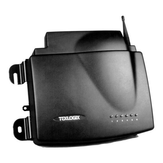
This allows wireless clients to access the network and also move seamlessly between the 9150s in the network. The 9150 can also operate as a Teklogix base station, remote radio module (RRM) or a mini-controller, and become part of a mapRF system. - Page 21 Chapter 1: Introduction About The 9150 Figure 1.1 The 9150 Wireless Gateway - Front View Figure 1.2 The 9150T Wireless Gateway - Bottom View Figure 1.3 The 9150DC Wireless Gateway - Bottom View Teklogix 9150 Wireless Gateway User Manual...
-
Page 22: Access Point Functions
IEEE 802.11b RF data link with terminals, and over a cable with the network controller or a host computer. The 9150 can be connected to the network through an Ethernet connection. The diagram in Figure 4.1 on page 65 illustrates a 9150 access point connection between a Teklogix 9400 Network Controller on Ethernet and IEEE 802.11 wireless devices. -
Page 23: Radio Options
Radio Options 1.4 Radio Options The 9150 supports Type II PCMCIA cards so that multiple radio interfaces are possible. There is one internal and one external PC card slot available. The type of PCMCIA radio card installed in the 9150 is dependent on your wireless network. Currently supported radios are: •... -
Page 24: Ieee 802.11B Protocol
Using bridging software, the 9150 Wireless Gateway enables communication between any wireless IEEE 802.11b-equipped stations and LAN stations operating on Ethernet. The 9150 itself is resident on the LAN and functions as a MAC bridge, providing transparent integration between the stations on the wireless and wired networks. -
Page 25: Inter-Access Point Protocol (Iapp)
LAN in a network that supports both TCP/IP and 802.IQ pro- tocol simultaneously. 802.IQ protocol is available in two versions: 802.IQv1 and 802.IQv2. The 9150 can support both versions of the protocol at the same time (ter- minals must use only one). - Page 26 Chapter 1: Introduction IEEE 802.11b Protocol 9150 Host Wireless Gateway ETHERNET TCP/IP 9100 PowerBaseT 9400 Network Controller 9150DC Wireless Gateway Figure 1.4 9150 Wireless Gateway: Wireless Access Point Configuration Teklogix 9150 Wireless Gateway User Manual...
-
Page 27: Security
802.1X defines the changes necessary to the operation of a MAC bridge in order to support port-based access control. 802.1X provides a means for MAC bridges, such as the 9150 in access point mode, to block packet traffic from individual ports until appropriate authentication for the port has occurred. - Page 28 IEEE 802.11b Protocol connects to the authenticator, which communicates on its behalf to the authentication server. The Psion Teklogix 7035, 8255, and 8260 terminals can act as supplicants. • Authenticator The “authenticator” is a MAC bridge that blocks packets originating from supplicants from being bridged to the wired network until the supplicant has been successfully authenticated.
-
Page 29: Adaptive Polling/Contention Protocol
If a “collision” occurs – more than one terminal attempts to respond in a particular window – the 9150 that is polling divides and reassigns that group until the colliding terminals can respond without a collision. - Page 30 For detailed information on configuring the 9150 as a base station, please see Chapter 5: “Base Station Configuration”. For a generalized system diagram, see Figure 1.5.
- Page 31 2.1.1 Environment ..... 17 2.1.1.1 9150 Wireless Gateway ... . 17 2.1.1.2 9100 PowerBaseT .
-
Page 33: Chapter 2: Installation Requirements
The 9150 should be situated away from the path of vehicles and free from water or dust spray. The 9150 should only be mounted in the upright position, as shown in Figure 2.1 on page 18. -
Page 34: 9100 Powerbaset
24. 2.1.2 Maintenance The 9150 has no internal option switches and does not require physical access; all configuration settings are done remotely (see Chapter 3: “9150 Main Configura- tion”). Environmental and radio communication considerations do still apply. -
Page 35: Power And Antenna Cables
30 cm of the unit. Secure the cables with ties to the cable tie mounts on the 9150 (see Figure 2.1 on page 18). A single phase power outlet (range 100 to 240 VAC rated 1.0A minimum) should be installed within one metre (3.1 feet) of the 9150. - Page 36 9150. The coaxial cable must be routed and secured using wire anchors and/or coaxial nail clips. A few extra inches of cable are required near the antenna and the 9150 to make disconnection easier. Teklogix 9150 Wireless Gateway User Manual...
-
Page 37: Connecting To External Devices
Once the 9150 is installed, connected and powered on, the system administrator can access the unit to check the configuration and to assign the 9150 its unique IP address. This may be done through the Console port or through the network (see “Connecting... -
Page 38: Lan Installation: Ethernet
The maximum packet size supported over the network is 1500 bytes. This parameter is not set at the 9150, but should be set at the host. For a description of port pinouts, please refer to Appen- dix B: “Port Pinouts And Cable Diagrams”. -
Page 39: Ethernet Cabling
The maximum cable segment length allowed between repeaters for both the 9150T and 9150DC (10BaseT/100BaseT Ethernet cabling) is 100 m. Note: For the 9150DC (see “Important” note on page 24), this cable length is measured from hub to 9150, including the mid-span insertion of the 9100 PowerBaseT. Important:... -
Page 40: 9100 Powerbaset Mid-Span Power Supply
100 m in length. See page 216 for power specifications. 19" Rack Mount RJ-45 Ports include LEDs for Powered Lines Console Port Figure 2.4 The 9100 PowerBaseT Teklogix 9150 Wireless Gateway User Manual... - Page 41 Chapter 2: Installation Requirements LAN Installation: Ethernet 9150DC Wireless Gateway 9150DC Wireless Gateway 9150DC Wireless Gateway 9150DC Wireless Gateway 9150 Wireless Gateway 9100 PowerBaseT SWITCH/HUB ETHERNET TCP/IP Host 9400 Network Controller Figure 2.5 9100 PowerBaseT System Architecture Teklogix 9150 Wireless Gateway User Manual...
- Page 42 Fast blink (all ports) Fast blink (all ports) supply fault Port in test mode Test Mode Fast blink Fast blink (enabled via console) Port disabled Test Mode Slow blink (via console) Table 2.1 LED Indicator States Teklogix 9150 Wireless Gateway User Manual...
-
Page 43: Status Indicators (Leds)
LEDs blink for all received and transmitted data traffic. (Note: the 9150DC only supports 802.11 radios.) LED #5 shows no activity, since the 9150T and 9150DC do not support serial connectivity. Built-in Self-Test. Table 2.2 9150T And 9150DC LED Functions: Front Enclosure Teklogix 9150 Wireless Gateway User Manual... -
Page 44: Connecting A Video Display Terminal
An ANSI compatible video display terminal (e.g., DEC VT220 or higher), or a PC running terminal emulation, is used for diagnostic purposes and to configure the 9150’s IP address for the first time (necessary before the 9150 can be accessed using a Web Browser; see “Configuring The IP Address” on page 31). - Page 45 3.4.7.1 Console Port ....58 3.4.7.2 Serial Port ....59 Teklogix 9150 Wireless Gateway User Manual...
- Page 46 3.6.1 System Info ..... .61 3.6.2 Reboot Unit..... .62 Teklogix 9150 Wireless Gateway User Manual...
-
Page 47: Chapter 3: 9150 Main Configuration
Before the configuration menus can be accessed using your web browser, the 9150 must be assigned an IP address using a PC console connection. Virtually any PC can be connected to the console port of the 9150, provided that the PC has a serial ®... - Page 48 To display the default gateway: >cfg get system.defaultgateway To configure the default gateway: >cfg put system.defaultgateway xxx.xxx.xxx.xxx To display the default subnetmask: >cfg get interface.1.defaultsubnetmask To configure the default subnetmask: >cfg put interface.1.defaultsubnetmask xxx.xxx.xxx.xxx Teklogix 9150 Wireless Gateway User Manual...
-
Page 49: Accessing The Menus
Accessing The Menus 3.3 Accessing The Menus When the web browser is pointed to the 9150’s IP address, a name and password dialog box appears. The password is comprised of alphanumeric characters and is case-sensitive. If you change the password (see “Users” on page 41), set all 9150s to the same password, and write it down in a secure place. - Page 50 Chapter 3: 9150 Main Configuration Accessing The Menus Figure 3.1 9150 Configuration Main Menu: View From Browser Teklogix 9150 Wireless Gateway User Manual...
-
Page 51: General Configuration Menu Options
3.4 General Configuration Menu Options The General Configuration menu on the Configuration Main Menu page presents five options of sub-menus: Interfaces, Users, SNMP, TCP/IP Parameters, and Serial Ports Parameters. Figure 3.2 Overview Of General Configuration Menus Teklogix 9150 Wireless Gateway User Manual... -
Page 52: Interfaces
9150’s physical (hardware) address and IP address parameters. Physical Address A unique Physical Address is assigned by Psion Teklogix personnel for each 9150. The values entered for this parameter are presented in hexadecimal in descending order beginning with the MSB (Most Significant Byte), the highest value, and ending with the LSB (Least Significant Byte), the lowest value. - Page 53 IP Address The Current IP Address shown in the read-only field is the IP address currently set on the 9150. The Default IP Address text box allows you to change the value of the IP address. The IP address must be a unique value on the network, so that each 9150 in your system can be identified.
-
Page 54: 100Baset Ethernet
For the selection 100BaseT Ethernet, entering the “Configure” dialog box will open the Onboard Fast Ethernet Parameters page for that Ethernet connection, which shows the 9150’s physical (hardware) address, and give access to the IP address, and Media Speed and Operating Mode parameters. - Page 55 IP Address The Current IP Address shown in the read-only field is the IP address currently set on the 9150. The Default IP Address text box allows you to change the value of the IP address. The IP address must be a unique value on the network, so that each 9150 in your system can be identified.
-
Page 56: Slot N: Pc Card Radio
3.4.1.3 Slot n: PC Card Radio Each PC Card (PCMCIA Card) radio resident in the 9150 will be located in one of two Slots: A or B. Selecting a PC card will open the sub-menu for that radio. IEEE 802.11 DS: See “IEEE 802.11 Direct Sequence Radio Parameters Menu” on page 66 for details on setting the radio parameters for the PC card. -
Page 57: Users
Chapter 3: 9150 Main Configuration Users 3.4.2 Users The Users option provides security for access to the 9150 Configuration menus. New individuals and their passwords can be added by selecting “[#] Create New” in the listbox before entering the “Configure” dialog box. -
Page 58: Snmp
The 9150 is fully compatible with Psion Teklogix’ MapRF network management software. For complete details on MapRF, please refer to the MapRF User Guide. Manual configuration of a 9150 in a MapRF system is minimal. The following parameters must be correctly configured: •... -
Page 59: System Parameters
The entries in these parameters set the name, contact and location identifiers for this specific 9150 Wireless Gateway. The entries should be of 7-bit, US-ASCII character type and not more than 78 characters. The name and location are then shown as the sub-heading of each Configuration page. -
Page 60: Enable Proxy For Non-Ip Terminals
3.4.3.4 Proxy throttling To ensure that increased radio traffic due to the 9150 acting as proxy does not create a problem, the amount of traffic can be controlled by setting it to 100, 500, or 1000 bytes per second. The default is Disabled. -
Page 61: Redundancy
Both the primary and secondary 9150s must be connected to the network, and each 9150 is aware of the other’s IP address. The secondary 9150 polls the primary 9150, and the primary 9150 responds, exchanging information about their status. There may not be more than one secondary 9150. - Page 62 IP addresses and the Backup IP Address parameter, which is the IP address of the other 9150. Note: When control of the Teklogix system is passed from one 9150 to the other, sessions between hosts and terminals are closed, and terminals and bases are reset.
- Page 63 9150 at intervals specified by the Poll Interval parame- ter. After each poll, this 9150 waits for a reply for the length of time specified by the Poll Timeout parameter. If there is no reply during this time period, the 9150 sends another poll to the other 9150.
- Page 64 When the secondary 9150 becomes the primary, it starts to use the alias IP address as well as its unique address, while the other 9150 stops using the alias IP address. Wireless devices in the system which communicate directly with the Teklogix network controller’s IP address, such as terminals using TCP Direct, may communi-...
-
Page 65: Sntp
The Time Zone Offset is the difference between the GMT and the local time where the 9150 is located. If you are not sure of your time zone offset, you can get the GMT by using the console command “ ?T ” five minutes after booting up the 9150. -
Page 66: Tcp/Ip Parameters
Note: The 9150 does not automatically compensate for Daylight Saving time. 3.4.6 TCP/IP Parameters If the 9150 is situated on a wired network, it uses TCP/IP. A Routing Table, Host Table, DHCP, Bootp, and DNS options are available to resolve IP addressing issues. -
Page 67: Route Table
Address textbox. Destination IP Address Enter the IP address of the host. If the host is on the same subnet as the 9150, enter its address here and in the Router IP Address textbox. Teklogix 9150 Wireless Gateway User Manual... -
Page 68: Host Table
TCP/IP Parameters 3.4.6.2 Host Table If no external DNS server is available, the 9150 may resolve host names to IP addresses using its internal host table. Host Table Hosts are added to the table by selecting “Configure” beside “[#] Add Entry” in the listbox. - Page 69 This parameter allows you to set the expiry time limit (in seconds) for the host name cache when the Host Table Entries parameter is set to Expire. The minimum allowable value is 30. The default value is 600. Teklogix 9150 Wireless Gateway User Manual...
-
Page 70: Network Interface Configuration Protocol
Network Interface Configuration Protocol The 9150 has designated default IP addresses for itself and the network Gateway. Alternatively, the IP address of the 9150 can be assigned by either a DHCP Server or BOOTP Server, if one is appropriately configured on the network. - Page 71 DHCP Lease Time This parameter defines the length of time (in days) that the 9150 is requesting for the lease on its IP address and subnet mask. The default setting is 0 (zero), which requests the maximum lease time configured at the DHCP Server.
-
Page 72: Dns
The Default Gateway Address creates an identifiable communication link between the 9150 and a network other than the one to which the 9150 is directly wired. The Gateway Address shown in the read-only field is the address currently assigned by the network administrator. - Page 73 If the query isn’t resolved, the DNS Resolver will then contact the second DNS Name Server. DNS Name Server 2 This is the IP address of the second designated DNS Name Server. Teklogix 9150 Wireless Gateway User Manual...
-
Page 74: Serial Ports Parameters
These parameters allow you to set the baud rates for the console port and the serial port. The Serial Ports Parameters “Configure” page, is entered from the Configura- tion Main Menu page. 3.4.7.1 Console Port Baudrate: The default baud rate for the console port is 19200 b/s. Teklogix 9150 Wireless Gateway User Manual... -
Page 75: Serial Port
Chapter 3: 9150 Main Configuration Serial Ports Parameters Modem Initialization String: The 9150 sends this string of ASCII characters through the console port when it reboots. Send It Now: Select this checkbox to send the modem initialization string without rebooting the 9150. -
Page 76: Access Point/Base Station/Mini-Controller Menus
For these operations, the parameters in these pages must be set appropriately. For detailed information on the sub-menus and to set up the 9150 as a base station, see Chapter 5: “Base Station Configuration”. To configure an access point device, see Chapter 4: “Access Point Configuration”. -
Page 77: Miscellaneous Commands Menu Options
There are two miscellaneous commands: System Info and Reboot Unit. 3.6.1 System Info The System Information, hardware and software, for the 9150 Wireless Gateway unit is detected automatically and summarized in this page. The screen is shown on page 62. -
Page 78: Reboot Unit
This option opens a dialog box which allows you to remotely “warm” reboot the 9150. If the OK button is chosen, the 9150 will be rebooted, the LEDs will turn off momentarily, and the following message will be received: Important:... - Page 79 4.6.1 Mobile IP Configuration ....99 4.6.1.1 Mobile Agent Parameters ....99 Teklogix 9150 Wireless Gateway User Manual...
- Page 80 4.7.2 RADIUS General Parameters ....103 4.7.3 RADIUS Servers ..... . 104 Teklogix 9150 Wireless Gateway User Manual...
-
Page 81: Chapter 4: Access Point Configuration
Overview 4.1 Overview The 9150 can operate as an access point device between wired networks and IEEE 802.11b wireless networks. Using IEEE 802.11b protocol, the 9150 provides a transparent bridge between Teklogix or client terminals and a network controller or host. -
Page 82: General Configuration Menu: Interfaces
4.2.1 IEEE 802.11 Direct Sequence Radio Parameters Menu When the Lucent WaveLAN IEEE 802.11 DSSS 2.4 GHz PCMCIA card is installed in the 9150, the IEEE 802.11 Direct Sequence Radio Parameter screen shown on the next page is opened from the Interfaces main menu. - Page 83 Chapter 4: Access Point Configuration IEEE 802.11 Direct Sequence Radio Parameters Menu Teklogix 9150 Wireless Gateway User Manual...
-
Page 84: Iq Version 1 Configuration Menu
802.IQv1 protocol is a wireless LAN protocol that provides greater performance in an 802.11b wireless network than is possible with TCP/IP. The 9150 bridges the 802.IQv1 wireless and TCP/IP wired networks. A terminal can communicate with the 9150 access point using either TCP/IP or 802.IQv1 protocol. -
Page 85: Iq V1/V2 Common Features Section
This parameter enables ( ) 802.IQ immediately when the 9150 is rebooted. When the 9150 is operating as a base station under a network controller or a 9150 mini- controller, this parameter must be disabled. The default value is disabled. -
Page 86: Iq V1 Configuration Section
If the base station was rebooted, or if the terminal moved to a different 9150, a warm initialize is done (no data will be lost). The Beacon Period parameter acceptable value ranges from 1 to 20 seconds. The default value is 2. - Page 87 Forward 802.IQ Packets Only When bridging packets between the wireless and wired systems, this parameter enables the 9150 to automatically filter out and discard all non-802.IQ packets. The default setting is disabled. Give Higher Priority To 802.IQ Data √...
-
Page 88: Radio Information
4.2.1.4 802.11 Radio Information The parameters in this section set general information about the Lucent WaveLAN IEEE 802.11 DSSS PCMCIA card installed in the 9150. Physical Address This parameter shows the hardware address (MAC address) of the radio card. A globally unique MAC address is assigned to each card by the card manufacturer. - Page 89 WEP Implemented on the card This parameter shows whether the radio card installed on the 9150 supports the Wired-Equivalent Privacy feature, referred to as WEP. This feature allows you to encrypt radio traffic to prevent electronic eavesdropping. WEP is available in either 64-bit or 128-bit encryption for the TRX7431 radio.
- Page 90 The default is disabled. WEP Tx Key This parameter specifies which WEP Key the 9150 will use when transmitting. The allowable values are 1 to 4. The default value is 1.
-
Page 91: Basic Service Set (Bss) Configuration
ESSID that is not equal to this 9150’s ESSID is NOT allowed. This prevents the 9150 from being associated with any station (802.11 device within radio range) that has its ESSID set to “ANY”... -
Page 92: Wireless Distribution System (Wds) Configuration
4.2.1.6 Wireless Distribution System (WDS) Configuration The 9150 Wireless Gateway can be used as an 802.11b wireless access point (AP) to extend coverage area or for locations difficult to wire; or two 9150s can be used as an 802.11b bridge connecting two separate wired networks. - Page 93 Chapter 4: Access Point Configuration IEEE 802.11 Direct Sequence Radio Parameters Menu MAC Address Of Remote AP Each wireless access point linked to this 9150 must be identified by entering its √ MAC address here, and the connection must also be enabled ( ).
- Page 94 Chapter 4: Access Point Configuration IEEE 802.11 Direct Sequence Radio Parameters Menu Figure 4.4 WDS: Multiple APs Connected To One AP On The Backbone Figure 4.5 WDS: Multiple APs Connected To Another Wireless AP Teklogix 9150 Wireless Gateway User Manual...
-
Page 95: Authenticator Configuration
9150, acting as an “authenticator”, passes their requests on to a separate “authentication server”. If the server approves the authentication request, the 9150 opens a port for the supplicant, and then acts as a bridge, passing packets between the supplicant and the wired network. - Page 96 The default value is 30 seconds. Max Requests This is the maximum number of times the 9150 will retransmit an EAP request to a supplicant before it ends the current authentication session. The default value is 2. Transmit WEP Key √...
-
Page 97: Access Point Configuration Menu Options
The MAC Bridge parameters consist of protocol filters that direct the 9150 to forward or discard frames that contain a known protocol type. This enables the 9150 to be selective of what types of frames will be bridged over the radio, in order to limit traffic on busy networks. - Page 98 Chapter 4: Access Point Configuration MAC Bridge Parameters Figure 4.6 Overview Of MAC Bridge Configuration Menus Teklogix 9150 Wireless Gateway User Manual...
-
Page 99: General Configuration
General Configuration 4.4.1 General Configuration Access Point Mode Enabled When this 9150 is used only as an 802.IQ base station and not as an access point, this parameter should be disabled to reduce CPU time. Only broadcast and √ multicast frames will be passed through. Enable ( ) this parameter for the 9150 functioning as an access point. - Page 100 If Protocol Filters Enabled is checked, and the Protocol Default Action is discard, an HTTP browser will not be able to access the 9150’s configuration pages unless an ARP filter is defined to forward ARP packets. To do this, configure Ethernet II Filters to forward protocol type 0x0806 (ARP) packets (see page 92).
-
Page 101: Bridge Spanning Tree Algorithm
ID. A lower numerical value for the bridge priority makes the bridge more likely to become the root. The default value is 61440 (which equals 0xF000 in hexadecimal notation). Teklogix 9150 Wireless Gateway User Manual... - Page 102 The value of the Maximum Age parameter sent in a Configuration BPDU (Bridge Protocol Data Unit) when the 9150 is the Root or is attempting to become the Root. The Maximum Age is the message age at which a received configuration message is judged “too old”...
-
Page 103: Address Filters: Mac Address
Valid values range from 0 to 255. The default value is 128. 4.4.2 Address Filters: MAC Address The 9150 can use a list of destination MAC addresses to filter out frames. The MAC addresses are those of any terminals associating with the 9150. If Address Filters √... - Page 104 If the action is shown as “Forward”, the frames for this address will be discarded. If the action is “Discard”, the frames will be forwarded. The parameter is not configurable in this menu. Teklogix 9150 Wireless Gateway User Manual...
-
Page 105: Protocol Filters
Protocol Filters 4.4.3 Protocol Filters When the 9150 receives frames, it can forward or discard the messages by filtering the protocol Type fields encapsulated in the frame. The filtering is done on three types of Ethernet headers: Ethernet II, LLC and SNAP. - Page 106 The listboxes in the Protocol Filters option show the protocol filters already set in the configuration database. Selecting a protocol name and then opening the “Con- figure” dialog box gives a list of parameter settings that can be modified or deleted for that protocol. Teklogix 9150 Wireless Gateway User Manual...
- Page 107 (for example, see “Ethernet II Filters” on page 92). When choosing to delete a filter, you will be prompted for confirmation of the dele- tion, which will give you the opportunity to cancel the action. Teklogix 9150 Wireless Gateway User Manual...
-
Page 108: Ethernet Ii Filters
For example, if you only use TCP/IP, create two protocol filters, one to forward IP (Type 0x0800) and the other to forward ARP (Type 0x0806). For a listing of Ethernet II types, see “Ethernet II Types (RFC 1700)” on page C-1. Teklogix 9150 Wireless Gateway User Manual... -
Page 109: Llc Filters
(DSAP/SSAP) parameter must be a four-digit hexadecimal number ranging from 0 to 0xFFFF, where the first pair of digits is the DSAP and the last pair is the SSAP. For a listing of DSAP/SSAP types, see “DSAP/SSAP Types” on page C-14. Teklogix 9150 Wireless Gateway User Manual... -
Page 110: Snap Filters
0 to 0xFFFF, which represents the SNAP type you wish to filter. √ When this parameter is enabled ( ), this Type will be filtered. For a short listing of OUI values, see “OUI Values” on page C-15. Teklogix 9150 Wireless Gateway User Manual... -
Page 111: Storm Detection
Setting the value for Restart is determined by the characteristics of your network. The default value is 150. Teklogix 9150 Wireless Gateway User Manual... -
Page 112: Mobility Configuration
LAN. Returning frames are no longer accepted by the original 9150, which has disassociated from that terminal. Returning frames are now accepted by the newly-associated 9150 and passed over the RF to the termi- nal. -
Page 113: Iapp Parameters
96. Handover Timeout If there is no response to the Handover request by the 9150 within the time specified in the Handover Timeout parameter, the request is retransmitted. If no response is received after a number of retries (set in the Handover Retries parameter, below), the 9150 will complete the reassociation procedure itself. -
Page 114: Mobile Ip Parameters
“agents” (9150s), which act as proxies. When the terminal roams away from its home network, the home agent will take all packets destined for the mobile node, and send them on to the foreign agent, which relays the packets to the “node” (terminal). Teklogix 9150 Wireless Gateway User Manual... -
Page 115: Mobile Ip Configuration
Advertisement Lifetime parameter value. This allows the mobile node to miss three successive advertisements before deleting the agent from its list of valid agents. The acceptable value ranges from 1 to 10. The default value is 4. Teklogix 9150 Wireless Gateway User Manual... -
Page 116: Mobile Node Parameters
The acceptable value ranges from 1 to 5. The default value is 1. Maximum Number Of Registered Mobile Nodes This parameter is the maximum number of terminals that can register with this 9150 acting as a home agent. The acceptable value ranges from 1 to 255. The default value is 128. -
Page 117: Supported Features
This parameter is the maximum number of sent gratuitous ARPs on the home net- work, when the home agent accepts a registration from a mobile node. The acceptable value ranges from 1 to 5. The default value is 3. Teklogix 9150 Wireless Gateway User Manual... -
Page 118: Security Configuration
The agent key must also match the key on the mobile node. The default value is TEKLOGIXTEKLOGIX. Replay Protection Timing Slack This parameter provides Timestamp-based replay protection. Important: In order for this parameter to operate, SNTP must also be enabled (see “SNTP” on page 49). Teklogix 9150 Wireless Gateway User Manual... -
Page 119: Authenticator Parameters
If the authenticator considers a RADIUS authentication server to be unreachable (in other words, the server has not replied after all of the authentication requests allowed by the Retries parameter), the authenticator won't try to connect to the same Teklogix 9150 Wireless Gateway User Manual... -
Page 120: Radius Servers
See also the Deadline and Retries parameters. Retries This parameter sets the total number of times (including the first time) that the 9150 will send an authentication request to the authentication server. See also the Timeout and Deadline parameters. - Page 121 5.5.1.3 Protocol Options ....146 5.5.1.4 Function Key Mappings ....146 Teklogix 9150 Wireless Gateway User Manual...
-
Page 123: Overview
As a wireless base station, the 9150 communicates with the wired base station and mobile terminals using the Wlan Protocol. As an RRM, the operation and timing of the 9150’s radio link to the terminals is directly controlled by a network controller that uses a timeplexing radio protocol (see “Timeplexing And Cellular Switching”, below). - Page 124 140. See Figure 5.2 on page 109 for an overview of the menus involved. Note: The 9150 main parameters should first be set up as described in Chapter 3: “9150 Main Configuration”. For details on the RF protocols, see page 13.
- Page 125 Chapter 5: Base Station Configuration Overview Figure 5.2 Overview Of Menus For Base Station Configuration Teklogix 9150 Wireless Gateway User Manual...
-
Page 126: Chapter 5: Base Station Configuration
5.2 General Configuration Menu: Interfaces 5.2.1 TekLAN Parameters The pull-down menu shown for the Interfaces option in the 9150 Configuration Main Menu page indicates which interfaces have been detected in use. Entering the “Configure” dialog box for “Slot A: TekLAN Card”, opens the parameters page for TekLAN, which presents both the radio and Wlan parameters. -
Page 127: Radio
Radio Radio Type The type of PC radio card installed on the 9150 is dependent on your wireless net- work. This parameter should be set to the installed radio. The TekLAN radio is the TekLAN 902 MHz DS Spread Spectrum. - Page 128 ) polling immediately when the 9150 is rebooted. If Auto-Startup is disabled, the 9150 will wait until polling is initialized from the network controller. When the 9150 is operating as a Wlan base station under a network controller, this parameter should be disabled.
-
Page 129: Wireless Lan Parameters
This parameter should be enabled ( √ ) if the 9150 is directly connected (wired) to the network. If the 9150 is a wireless base station, this parameter should be disabled. The default setting is enabled. Timeout This value is used to adjust Wlan performance and should be set to 10. -
Page 130: Narrow Band Radio Parameters
“General Options” When you select this sub-menu, the page displayed allows you to set the operat- ing options for the 9150 in either base station or RRM mode, and to retrieve the radio card’s permanent communications settings. “Connectivity Options”... - Page 131 Chapter 5: Base Station Configuration Narrow Band Radio Parameters There is also a Main Menu button. When you select this button, the 9150 displays the Configuration Main Menu (see page 109). Figure 5.4 Overview Of Teklogix Narrow Band Menus Teklogix 9150 Wireless Gateway User Manual...
-
Page 132: General Options
If changing radio types in the 9150, DO NOT “hot swap” the PC cards: turn the 9150 off before changing the radio. Operating Mode This parameter allows you to set the operating mode of the 9150 as Base Station or RRM. 5.2.2.2 TRX7370 Radio Card Parameters Entering the “Get Card Parameters”... - Page 133 Chapter 5: Base Station Configuration Narrow Band Radio Parameters Teklogix 9150 Wireless Gateway User Manual...
- Page 134 Chapter 5: Base Station Configuration Narrow Band Radio Parameters General Parameters Frequencies Teklogix 9150 Wireless Gateway User Manual...
- Page 135 Chapter 5: Base Station Configuration Narrow Band Radio Parameters Tuning Values Teklogix 9150 Wireless Gateway User Manual...
-
Page 136: Connectivity Options: Base Station Mode
Narrow Band Radio Parameters 5.2.2.3 Connectivity Options: Base Station Mode When you enter the Connectivity Options sub-menu for the 9150 set in base station operating mode, the 9150 displays the Polling Protocol Parameters and Radio Parameters. Teklogix 9150 Wireless Gateway User Manual... - Page 137 ), it imposes timing restrictions for polling. Every 2 seconds of polling is followed by 0.5 seconds of silence—no polling occurs. Further, if another carrier is detected on the channel, the 9150 will cease radio trans- missions on that channel until the path is clear.
- Page 138 This parameter determines the largest single message that can be passed to a terminal in message mode or from a terminal in long message mode. In a 9150 base station, the value entered in this parameter must be greater than or equal to the value entered in the network controller or 9150 mini-controller.
- Page 139 Collision Size This parameter reduces the probability that random noise on the radio link will be interpreted as a collision between terminals. Response time increases when the 9150 resolves collisions unnecessarily. Collision Size places an upper limit on the number of characters that are received prior to the receipt of an error message (CRC, CD lost, etc.).
- Page 140 Remote Txon accommodates the turn on time of the radio in terminals (remotes). It specifies the number of fill characters sent to the radio before real data is output. Since this parameter is based on character times, the number is dependent on the radio link baud rate. Teklogix 9150 Wireless Gateway User Manual...
-
Page 141: Connectivity Options: Rrm Mode
When you enter the Connectivity Options sub-menu for the 9150 set in RRM operat- ing mode, the 9150 displays the RRM parameters. Port This parameter allows you to enter the port number of the 9150. The port number can range from 1024 to 32767. Important: The port number entered here must match the port number entered for this 9150 in the network controller’s RRM configuration. -
Page 142: Base Station Configuration Menu Options
(Teklogix 9400 Network Controller or 9150 Wireless Gateway), using a range of host platforms. Alternatively, the network controller can be a host running a Teklogix SDK (handler). The 9150 can also act as a slave base station to another 9150 on the network. - Page 143 When this parameter is enabled ( ), the slave base stations will start polling when the master 9150 boots up. When Auto-Startup is disabled, the base stations will not start polling until they receive a start polling command from the host.
-
Page 144: Rrm Groups
While the 9150 can operate as a Remote Radio Module (RRM, see “Connectivity Options: RRM Mode” on page 125), it can also control other RRMs. For a 9150 to control RRMs, RRM groups must be configured. Once an RRM group has been defined, from one to four RRMs can be members of a group (see “RRM Group... - Page 145 Chapter 5: Base Station Configuration RRM Groups Name This textbox allows the user to enter a name for the new RRM group. The value is any text string. The default is Unnamed RRM Group. Teklogix 9150 Wireless Gateway User Manual...
- Page 146 ), the 9150 checks for other traffic on the radio channel used by this RRM group, before polling. If this parameter is disabled, the 9150 assumes that it has exclusive use of the radio channel for this RRM group, and polls without checking for radio traffic.
- Page 147 This textbox allows the user to specify the probability that the RRM will include a free window in its poll, during which any terminal may transmit. The allowable values range from 0 to 7. The default value is 0. Teklogix 9150 Wireless Gateway User Manual...
- Page 148 Because some of the radio parameters are identical for a given group of timeplexed RRMs, they may be configured by the user once on the 9150; the 9150 then passes them to the RRMs in the group. These parameters include the synchronization delay (Sync Delay), the remote transmit on-time (Remote Txon), and the channel number to be used (Active Channel).
- Page 149 The combinations use the RRMs in the order that they appear in the list, not how they are numbered in the list. RRMs that are not assigned to combinations poll individually, after the combina- tions poll. Teklogix 9150 Wireless Gateway User Manual...
-
Page 150: Rrm Group Menu
RRMs When the user selects the name of an existing RRM from the listbox, then presses this Configure button, the 9150 displays the RRM Options screen for that RRM. There is also a selection in the listbox, Create New, for adding a new RRM. - Page 151 RRM Group from the RRM Groups list. When choosing to delete an RRM Group, you will be prompted for confirmation of the deletion, which will give you the opportunity to cancel the action. Teklogix 9150 Wireless Gateway User Manual...
-
Page 152: Radio Link Features
Note: The 9400 Network Controller must also be set to cellular mode. Poll ID In Wlan protocol, this is a unique identifying number set only in a 9150 master base station, 9150 mini-controller or a network controller, which is used in the poll header when polling terminals. - Page 153 Direct TCP Connections for TekTerm Enabling this parameter allows the TekTerm program resident in Teklogix terminals to connect directly to the 9150, when it is acting as a base station to a host via TCP/IP. Teklogix 9150 Wireless Gateway User Manual...
- Page 154 2. The Auto ID parameter in the terminal must be enabled in order for the radio address to be automatically assigned. 3. Do not enable Auto Startup (see page 69) on any of the 9150 base sta- tions running 802.IQ with sessions using Automatic Radio Address Assignment Range and Automatic Terminal Number Assignment Range.
- Page 155 2. The Auto Session parameter in the terminal must be enabled in order for the terminal session number to be automatically assigned. 3. Do not enable Auto Startup (see page 69) on any of the 9150 base sta- tions running 802.IQ with sessions using Automatic Radio Address Assignment Range and Automatic Terminal Number Assignment Range.
-
Page 156: Hosts Menu
Hosts Menu 5.4 Hosts Menu When the 9150 acts as a base station, it must communicate with a “host” - a 9400 Network Controller, or a host computer using a Teklogix Software Development Kit (TSDK). The drop-down menu in the Mini-Controller Configuration: Hosts option in the Configuration Main Menu page shows the host names present on the system. - Page 157 Emulation and Protocol This drop-down menu provides a list of host emulations and communication protocols supported by the 9150. Protocols are the methods by which terminals communicate with host computers over various physical media such as Ethernet and radio-link connections.
- Page 158 For detailed information, please refer to the appropriate Teklogix User Manual for: 9400 Network Controller, TSDK, TESS or ANSI. However, when the 9150 acts as a mini-controller, it uses the 3274 and 5250 emula- tion protocols to communicate with IBM hosts, or the ANSI emulation protocol to communicate with ANSI hosts.
-
Page 159: Host Menu Options
5.5 Host Menu Options When you choose an existing host from the Hosts listbox and then select the Config- ure button, the 9150 displays the Host Menu. Figure 5.5 Overview Of Host Menus For 9010 / TCP/IP Teklogix 9150 Wireless Gateway User Manual... -
Page 160: 9010 / Tcp/Ip
This page may vary depending on the type of emulation and protocol selected for the host. There is also a Main Menu button. When you select this button, the 9150 displays the Configuration Main Menu (see page 109). -
Page 161: Emulation Options
), the 9150 base station does not notify the host if the status of a terminal changes between offline and online. If this parameter is disabled, the 9150 does notify the host regarding any terminal status changes. The default for this parameter is disabled. -
Page 162: Protocol Options
9010 / TCP/IP 5.5.1.3 Protocol Options 9010/Telnet Options: Monitor Polls Hosts usually send messages or null polls to the 9150 within a period of approxi- √ mately 40 seconds. If the parameter is enabled ( ), the 9150 base station monitors messages and polls from this host;... - Page 163 6.5.1 802.IQ Version 2 Configuration ..201 6.5.1.1 802.IQ v1/v2 Common Features ..202 6.5.1.2 802.IQ v2 Configuration Sub-Screen ..203 Teklogix 9150 Wireless Gateway User Manual...
-
Page 165: Chapter 6: Mini-Controller Configuration
The 9150 is equipped with emulation capabilities, allowing it to act as a mini- controller. When a 9150 is configured as a mini-controller, Teklogix terminals can emulate an ANSI, 5250 or 3274 terminal via a 9150 rather than through a 9400 Network Controller. Using the RF Modem/Telnet emulation, the 9150 can also communicate with a Teklogix 6040 RF Modem. - Page 166 9150 Wireless Gateway 8055 Vehicle-Mount RF Terminal 9150 Wireless Gateway Mini-Controller ETHERNET TCP/IP 7035 9150 Wireless Gateway 7030 Hand-Held Hand-Held Base Station and Access Point RF Terminal RF Terminal Figure 6.1 9150 Mini-Controller Configuration Teklogix 9150 Wireless Gateway User Manual...
-
Page 167: Mini-Controller Configuration Menu
Controller Configuration should be set appropriately. The Hosts options are found on the Configuration Main Menu page. For information on configuring radio proto- col parameters, please refer to “Radio Link Features” on page 136. Teklogix 9150 Wireless Gateway User Manual... -
Page 168: Hosts Menu
A “host” must be configured for each host that com- municates with the 9150 mini-controller. Opening the Configure dialog box for a selected host lists the parameters that can be modified or deleted for that host. - Page 169 • RF Modem/Telnet (See page 200 for Configuration Parameters). When the 9150 acts as a base station, it uses the 9010 emulation (a proprietary asynchronous protocol developed by Psion Teklogix) to communicate with a 9400 Network Controller or a host using a Teklogix Software Development Kit (TSDK).
- Page 170 The values entered in this parameter designate the first and last terminals in the range of terminals that will communicate with the host. These terminal numbers are mapped to this particular host. Terminal numbers may range from 1 to 50. Teklogix 9150 Wireless Gateway User Manual...
-
Page 171: Host Menu Options
6.4 Host Menu Options When you choose an existing host name from the Hosts listbox and then select the Configure button, the 9150 displays the Host Menu. The Host Menu presents the options for four sub-menus: General Host Options, Emulation Options, Protocol Options, and Function Key Mappings. - Page 172 As illustrated in Figure 6.2 on page 155, the four configuration sub-menus display the following options: “General Options” When you select this sub-menu, the 9150 displays the General Options page for the host. “Emulation Options” When you select this sub-menu, the 9150 displays the Emulation Options page for the host.
-
Page 173: General Options
The left-hand textbox contains the lowest terminal number which is allowed to communicate with the host; the right-hand textbox contains the highest terminal number. Terminal numbers may range from 1 to 50. Teklogix 9150 Wireless Gateway User Manual... -
Page 174: 9010 Emulations
6.4.2 9010 Emulations When the 9150 acts as a base station, it uses the 9010 protocol (a proprietary asyn- chronous protocol developed by Psion Teklogix) to communicate with a 9400 Network Controller, or a host using a Teklogix Software Development Kit (TSDK). - Page 175 Chapter 6: Mini-Controller Configuration 3274/Telnet Teklogix 9150 Wireless Gateway User Manual...
- Page 176 3274/Telnet Is Host Fujitsu If this parameter is enabled, the 9150 mini-controller expects the data from the host to contain commands, etc., native to a Fujitsu host. Enabling this parameter causes the standard IBM formatting codes (for start of field, setting buffers, etc.) to be replaced by the codes used by Fujitsu host computers.
- Page 177 Note: This operation is only performed on screens received from the host. Data sent to the host remains unaffected. Passthru If this parameter is enabled, the 9150 allows the host to send data directly to the RF terminal’s serial port. This is most commonly used for printing. Preparing Host Screens for Pass-Through On the screen to be sent through the terminal serial port, the word PASSTHRU (in capital letters) must appear on the first line, starting on the second column.
- Page 178 Chapter 6: Mini-Controller Configuration 3274/Telnet Local If this parameter is enabled, the 9150 allows the host to provide pages to be loaded as local TESS procedures in the terminals. The local procedures are selected from a menu at the terminal. The terminals can perform these procedures when they are offline.
- Page 179 Terminals User Manual for more information. Remote Print When this parameter is enabled, the 9150 sends the print page to a terminal when- ever the terminal requests it (by sending the “F17” function key from the terminal, or the “PRINT” key on older terminals). The 9150 sends the function response back to the host.
- Page 180 The 9150 reduces data transmitted to the terminals by using the terminal’s capability to store a page of data for each screen it displays. The 9150 maintains an image of each page stored at the terminal. After receiving an application screen, the 9150 tries to match the screen with a stored page.
- Page 181 Add 16 to above values to indicate cursor position priority for search and fill. AIAG Prefix The text to be matched in the AIAG field. (data) Table 6.1 Mode Functions And AIAG Prefix Description Teklogix 9150 Wireless Gateway User Manual...
- Page 182 By inserting a special ASCII character directly before an entry field, the application program distinguishes a “match field” from an entry field. For example, suppose an angle bracket “ ” is defined for visible match fields. > Teklogix 9150 Wireless Gateway User Manual...
- Page 183 ASCII characters. A value of 0 disables this feature. The ASCII decimal value entered at the 9150 must coincide with the value set by the application program. To use the Visible Match feature, the host computer preloads data into a match entry field;...
- Page 184 The range for this parameter – 0 to 127 – represents the decimal values of ASCII characters. A value of 0 disables this feature. The ASCII decimal value entered at the 9150 must coincide with the value set by the application program. Serial I/O Serial I/O fields are special entry and fixed fields that accept input from and output to a serial port.
- Page 185 This parameter contains the maximum number of characters allowed between two fixed fields which still allows the 9150 to join them into one field. Sometimes the 9150 will join two adjacent fixed fields and then send them as one field. This reduces the overhead on the radio link.
-
Page 186: Protocol Options
Protocol Options page when you select the emulation/protocol combination of 3274/Telnet for this host. Terminal Type This parameter allows you to choose the type of terminal to be emulated by the 9150 for this host. At present there is only one choice of terminal for 3274/Telnet: the IBM 3278-2. - Page 187 If this parameter is enabled, the 9150 sends the IAC Interrupt Process request to the host as a 3274 System Request. Send IAC Break as an Attention Key If this parameter is enabled, the 9150 sends the IAC Break request to the host as a 3274 Attention key. Teklogix 9150 Wireless Gateway User Manual...
- Page 188 (turned on and operating properly on the Teklogix RF network). Auto-telnet Host This parameter contains the host name or IP address for the host to which the 9150 connects Auto-telnet sessions. Note: A host name placed in this textbox must be “resolvable” by the 9150: the 9150 must be able to obtain an IP address for it.
-
Page 189: Function Key Mappings
Function Key Mappings This page differs depending on the type of emulation selected in the General Host Options page. The 9150 displays this version of the Function Key Mapping page when you select 3274 emulation for this host. Function key n The Function Key parameter allows you to select a code that will be sent to the host when you press a function key on the terminal. -
Page 190: 5250/Telnet
Chapter 6: Mini-Controller Configuration 5250/Telnet 6.4.4 5250/Telnet 6.4.4.1 Emulation Options Teklogix 9150 Wireless Gateway User Manual... - Page 191 9150 sends the error codes as regular screen text. Use International EBCDIC If this parameter is enabled, the 9150 will swap the positions of the ! and ] charac- ters in the EBCDIC character table. Allow null character in fixed fields: If this parameter is enabled, the 9150 mini-controller allows null characters in the whitespace in fields that have visual video attributes (such as reverse video).
- Page 192 Note: This operation is only performed on screens received from the host. Data sent to the host remains unaffected. Passthru If this parameter is enabled, the 9150 allows the host to send data directly to the RF terminal’s serial port. This is most commonly used for printing. Preparing Host Screens for Pass-Through On the screen to be sent through the terminal serial port, the word “PASSTHRU”...
- Page 193 TESS execute procedure command. Local If this parameter is enabled, the 9150 allows the host to provide pages to be loaded as local TESS procedures in the terminals. The local procedures are selected from a menu at the terminal. The terminals can perform these procedures when they are offline.
- Page 194 Terminals User Manual for more information. Remote Print When this parameter is enabled, the 9150 sends the print page to a terminal when- ever the terminal requests it (by sending the “F17” function key from the terminal, or the “PRINT” key on older terminals). The 9150 sends the function response back to the host.
- Page 195 The 9150 reduces data transmitted to the terminals by using the terminal’s capability to store a page of data for each screen it displays. The 9150 maintains an image of each page stored at the terminal. After receiving an application screen, the 9150 tries to match the screen with a stored page.
- Page 196 Add 16 to above values to indicate cursor position priority for search and fill. AIAG Prefix The text to be matched in the AIAG field. (data) Table 6.3 Mode Functions And AIAG Prefix Description Teklogix 9150 Wireless Gateway User Manual...
- Page 197 “match field” from an entry field. For example, suppose an angle bracket “ ” is defined for visible match fields. Inserting “ ” immediately > > preceding the entry field identifies it as a match field, as illustrated below. Part #> ___________ Teklogix 9150 Wireless Gateway User Manual...
- Page 198 ASCII characters. A value of 0 disables this feature. The ASCII decimal value entered at the 9150 must coincide with the value set by the application program. To use the Visible Match feature, the host computer preloads data into a match entry field;...
- Page 199 The range for this parameter – 0 to 127 – represents the decimal values of ASCII characters. A value of 0 disables this feature. The ASCII decimal value entered at the 9150 must coincide with the value set by the application program. Serial I/O Serial I/O fields are special entry and fixed fields that accept input from and output to a serial port.
- Page 200 This parameter contains the maximum number of characters allowed between two fixed fields which still allows the 9150 to join them into one field. Sometimes the 9150 will join two adjacent fixed fields and then send them as one field. This reduces the overhead on the radio link.
-
Page 201: Protocol Options
5250/Telnet for this host. Terminal Type This parameter allows you to choose the type of terminal to be emulated by the 9150 for this host. At present there are two choices of terminal for 5250/Telnet: the IBM 5251-11 and IBM 5555-B01. - Page 202 First Terminal Listen Port This parameter specifies the first port number at which the 9150 will listen for telnet connection requests to the terminals. To enable this parameter, the value must be a minimum of 1024.
- Page 203 (turned on and operating properly on the Teklogix RF network). Auto-telnet Host This parameter contains the host name or IP address for the host to which the 9150 connects Auto-telnet sessions. Note: A host name placed in this textbox must be “resolvable” by the 9150: the 9150 must be able to obtain an IP address for it.
-
Page 204: Function Key Mappings
Function Key Mappings This page differs depending on the type of emulation selected in the General Host Options page. The 9150 displays this version of the Function Key Mapping page when you select 5250 emulation for this host. Function key n The Function Key parameter allows you to select a code that will be sent to the host when you press a function key on the terminal. -
Page 205: Ansi/Telnet
6.4.5 ANSI/Telnet 6.4.5.1 Emulation Options The 9150 displays this version of the Emulation Options page after you have selected the ANSI/Telnet emulation/protocol combination for this host connection. Maximum Screen Size The Maximum Screen Size allows you to set the maximum required screen size in terminals, by rows and columns. - Page 206 The Threshold is the minimum number of bytes of update data for the terminal screen which must be received from the host before the 9150 will store the screen as a new “saved page”. The range is 0 to 999, with a default value of 200.
- Page 207 9150 instructs the terminal to redisplay its stored copy of the page; no data need be sent across the radio link for that page. If the 9150 finds no match for the page, the complete page is sent to the terminal.
-
Page 208: Protocol Options
Note: This option should only be used when using double byte character sets. If this parameter is enabled, the 9150 uses run-length encoding (RLE) on the data it sends across the radio link. RLE compresses repeated characters going from the host to the terminal. - Page 209 ANSI/Telnet Terminal Type This parameter specifies the type of terminal to be emulated by the 9150. The char- acters entered in the textbox can be any ASCII string acceptable to the host, with a maximum of 32 characters. The default value is VT100.
- Page 210 First Terminal Listen Port This parameter specifies the first port number at which the 9150 will listen for telnet connection requests to the terminals. To enable this parameter, the value must be a minimum of 1024. To disable the listen port, the value must be 0.
- Page 211 When Auto-telnet is disabled, telnet sessions from the terminals to the host must be initiated manually from the terminals. When Auto-telnet is enabled, the 9150 initiates one telnet session from each termi- nal whose terminal number is mapped to this host. Additional telnet sessions may be initiated from each terminal to the host, but they must be initiated manually.
- Page 212 Chapter 6: Mini-Controller Configuration ANSI/Telnet Auto-telnet Host This parameter contains the host name or IP address for the host to which the 9150 connects Auto-telnet sessions. Note: A host name placed in this textbox must be “resolvable” by the 9150: the 9150 must be able to obtain an IP address for it.
- Page 213 ANSI/Telnet Auto-login User ID prompt The 9150 compares the text in this textbox to the text presented to it by the host. When they match, the 9150 assumes that the host has just sent its request for a user name, and it sends the user ID specified in the Auto-Login User ID parameter to the host.
- Page 214 ANSI/Telnet Allow TCP Sessions When this parameter is enabled, the 9150 allows a terminal user to switch prompts or sessions while at the prompt (either Auto-login or TCP). If Allow TCP Sessions is disabled, all new sessions will open as Auto-login sessions.
-
Page 215: Function Key Mappings
Function Key Mappings This page differs depending on the type of emulation selected in the General Host Options page. The 9150 displays this version (page 200) of the Function Key Mapping page after you have selected the ANSI/Telnet emulation/protocol combina- tion for the host connection. -
Page 216: Rf Modem/Telnet
RF Modem/Telnet is intended for a controller communicating with a Teklogix Model 6040 RF Modem. The 6040 acts as a terminal on the Psion Teklogix network to allow serial devices to communicate over that network (see the 6040 RF Modem User Manual for details). -
Page 217: Function Key Mappings
802.IQ V2 Features Menu First Terminal Listen Port This parameter specifies the first port number at which the 9150 will listen for telnet connection requests to the terminals. To enable this parameter, the value must be a minimum of 1024. To disable the listen port, the value must be 10000. The default value is 10000 (disabled). -
Page 218: Iq V1/V2 Common Features
This parameter enables ( ) 802.IQ immediately when the 9150 is rebooted. When the 9150 is operating as a base station under a network controller or a 9150 mini- controller, this parameter must be disabled. The default value is disabled. -
Page 219: Iq V2 Configuration Sub-Screen
If the base station was rebooted, or if the terminal moved to a different 9150, a warm initialize is done (no data will be lost). The Beacon Period parameter acceptable value ranges from 1 to 20 seconds. The default value is 2. - Page 221 7.1.3 Power Monitoring ....208 7.2 Diagnostics and Status Reporting ....208 Teklogix 9150 Wireless Gateway User Manual...
-
Page 223: Chapter 7: 9100 Monitoring/Diagnostics
Subsequently, the microcontroller will turn the port power OFF immediately upon detection of an overcurrent condition. Note: There is a five-second safety period before the 9100 begins resistor detection on a port that has triggered the overcurrent detection. Teklogix 9150 Wireless Gateway User Manual... -
Page 224: Power Monitoring
A fault condition will be indicated by the LEDs and on the console until the fault is cleared, either by the resistor detection for that port succeeding and the port being switched ON, or disabling and re-enabling the port from the console. Teklogix 9150 Wireless Gateway User Manual... - Page 225 If everything remains within operating specifica- tion, the port will remain in the ON state. Fault conditions may transition the port to the Low Current fault or High Current fault state. Teklogix 9150 Wireless Gateway User Manual...
- Page 226 OFF state. The port will continue to indicate the High Current fault until it either transitions to the ON state, or is disabled via the console. Teklogix 9150 Wireless Gateway User Manual...
- Page 227 PECIFICATIONS 8.1 Specifications For The 9150 Wireless Gateway ..213 8.1.1 Physical Description ....213 8.1.2 9150T Power Requirements ... . 213 8.1.3 9150DC Power Requirements .
-
Page 229: Chapter 8: Specifications
Chapter 8: Specifications Specifications For The 9150 Wireless Gateway Note: Performance specifications are nominal and subject to change without notice. 8.1 Specifications For The 9150 Wireless Gateway 8.1.1 Physical Description Enclosure Bayer Makroblend EL-700 (PC/PET blend), jet black in colour, texture to... -
Page 230: Environmental Requirements
TRX7370 Narrow Band DSP Transmit Power 2.0 W (North America) 0.5 to 2.0 W (International) Frequency Range 403 to 512 MHz Data Rate 4800, 9600, 19200 b/s (dependent on modulation and frequency) No. of Channels Teklogix 9150 Wireless Gateway User Manual... -
Page 231: Approvals
8.1.8 Approvals FCC Part 15, subpart B, Class B Electrical Safety: CSA/NRTL, TÜV, CB Scheme ETS 300 113 ETS 300 220 ETS 300 086 ETS 300 328 CE Mark: EN 55022: 1998 EN 55024: 1998 Teklogix 9150 Wireless Gateway User Manual... -
Page 232: Specifications For The 9100 Powerbaset
9150DC. Note: The 9100 has no effect on the data passed through it. 48VDC is inserted on the spare pins/conductors of the cable to the 9150DC. 8.2.4 Electrical Safety Approvals CSA/NRTL/C and CB certificate Teklogix 9150 Wireless Gateway User Manual... -
Page 233: Lucent/Agere Wavelan Pc Card Regulatory Information
RF exposure compliance. Refer to the Regulatory Statements as identified in the documentation that comes with those additional information. products for Teklogix 9150 Wireless Gateway User Manual... - Page 234 The correction of interference caused by such unauthorized modification, substitu- tion or attachment will be the responsibility of the user. For country-specific approvals, please consult the flyer “Radio Certification Infor- mation” that is included with the 9150 Wireless Gateway. Teklogix 9150 Wireless Gateway User Manual...
-
Page 235: Appendix A: Support Services And Worldwide Offices
A.1.1 Canada and U.S.A: Technical Support and Repair Services In Canada and the U.S.A. these services can be accessed through the Psion Teklogix Helpdesk. The Helpdesk coordinates repairs, helps you troubleshoot problems over the phone, and arranges for technicians or engineers to come to your site. - Page 237 E-mail: salescdn@psion.com E-mail: salesusa@psion.com NTERNATIONAL UBSIDIARIES Psion Teklogix GmbH Psion Teklogix Finland Psion Teklogix de Mexico, S.A. de C.V. Jakob Kaiser Straße 3 Metsänneidonkuja 8 Sierra Mojada 626, 2º Piso D-47877 Willich Münchheide 02130 Espoo Col. Lomas Barrilaco, C.P. 11010...
-
Page 238: Worldwide Web
Waterfall Edge Phase 2, Waterfall Park Nederlands Bekker Road MIDRAND 1685 Tel: +31 77 32400 44 South Africa Fax: +31 77 32400 53 Tel: +27 11 805 7440/1/2 Fax: +27 11 805 7444 A.3 W ORLDWIDE www.psionteklogix.com Teklogix 9150 Wireless Gateway User Manual... -
Page 239: Console Port
PPENDIX INOUTS ABLE IAGRAMS B.1 Console Port Pin No. Name Function Direction Transmit Data Receive Data Signal Ground – Data Terminal Ready Request to Send * always pulled high Teklogix 9150 Wireless Gateway User Manual... -
Page 240: Serial Cable Descriptions
Appendix B: Port Pinouts And Cable Diagrams Serial Cable Descriptions B.2 Serial Cable Descriptions Standard Cable No. Function Connection Length 19387 9150 to Console Direct 6 feet Console Port Cable No. 19387 Teklogix 9150 Wireless Gateway User Manual... -
Page 241: Connector Pinouts (10Baset/100Baset Ethernet
(P/N 97776) is placed on the cable as closely as possible to the RJ-45 jack. To determine which version of the MLB is resident in your 9150, please contact Psion Teklogix Support Services (see page A-1). -
Page 242: 9100 Powerbaset Console Port Pinout
UART with baud generator, 8 or 9 data bits, noise filtering, overrun detection, framing error detection, and interrupts. The transceiver is 5 V powered with two drivers and two receivers with extra protection against ESD. Teklogix 9150 Wireless Gateway User Manual... - Page 243 Console Serial Data Input Console Serial Data Output Programming/ Data Output to the PROGRAM_DATA_OUT programmer Download Console and Programming/ Ground Download Programming/ Clock Input from the PROGRAM_CLOCK programmer Download Programming/ PROGRAM_EN Programming enable Download Teklogix 9150 Wireless Gateway User Manual...
-
Page 245: Ethernet Ii Types (Rfc 1700
0x8036 Allen-Bradley 0x80E0-0x80E3 Alpha Micro 0x814A Apollo Computer 0x80F7 Apollo Computers 0x8019 Appletalk 0x809B AppleTalk AARP (Kinetics) 0x80F3 Applitek Corporation 0x80C7 Apricot Computers 0x81CC-0x81D5 ARAI Bunkichi 0x81A4 0x0806 Artisoft 0x81D6-0x81DD Ascom Banking Systems 0x8221-0x8222 Teklogix 9150 Wireless Gateway User Manual... - Page 246 Bridge Communications 0x8132-0x8136 Cabletron 0x7034 Chaosnet 0x0804 Charles River Data System 0x8164-0x8166 Charles River Data System 0x8263-0x826A ComDesign 0x806C Computer Network Tech 0x869E-0x86A1 Computer Protocol Pty Ltd. 0x815C-0x815E Computgraphic Corp. 0x806D Comsat Labs 0x81F0-0x81F2 Teklogix 9150 Wireless Gateway User Manual...
- Page 247 DEC LAVC, SCA 0x6007 DEC MOP Dump/Load 0x6001 DEC MOP Remote Console 0x6002 DEC Unassigned 0x6008-0x6009 DEC Unassigned 0x8039-0x803C DEC Unassigned 0x803E DEC Unassigned 0x8040-0x8042 DEC Unassigned (Exp.) 0x6000 Delta Controls 0x86DE DLOG 0x0660 DLOG 0x0661 Teklogix 9150 Wireless Gateway User Manual...
- Page 248 0x80C8-0x80CC Internet IP (IPv4) 0x0800 Invisible Software 0x8A96-0x8A97 ISC Bunker Ramo 0xFF00-0xFF0F Kinetics 0x80F4-0x80F5 0x8139-0x813D Landis & Gyr Powers 0x86E0-0x86EF Landmark Graphics Corp. 0x806E-0x8077 Little Machines 0x8060 Logicraft 0x8148 Loopback 0x9000 0x7020-0x7029 Matra 0x807A Teklogix 9150 Wireless Gateway User Manual...
- Page 249 PUP Addr Trans 0x0A01 Qualcomm 0x8151-0x8153 Qualcomm 0x819A-0x81A3 Quantum Software 0x8203-0x8205 RAD Network Devices 0x81A5-0x81AE Rational Corp 0x8150 Retix 0x80F2 Reverse ARP 0x8035 Rosemount Corporation 0x80D3-0x80D4 SAIC 0x81F3-0x81F5 SECTRA 0x86DB SGI bounce server 0x8016 Teklogix 9150 Wireless Gateway User Manual...
- Page 250 Ungermann-Bass net debugr 0x0900 Univ. of Mass. @ Amherst 0x8065 Univ. of Mass. @ Amherst 0x8066 Valid Systems 0x1600 Varian Associates 0x80DD Veeco Integrated Auto. 0x8067 VG Analytical 0x81F6-0x81F8 VG Laboratory Systems 0x8131 Vitalink Communications 0x807D-0x807F Teklogix 9150 Wireless Gateway User Manual...
- Page 251 Vitalink TransLAN III 0x8080 Walker Richer & Quinn 0x82AC-0x8693 Wellfleet Communications 0x80FF-0x8103 X.25 Level 3 0x0805 X.75 Internet 0x0801 Xerox IEEE802.3 PUP 0x0A00 XEROX NS IDP 0x0600 XNS Compatibility 0x0807 Xyplex 0x0888-0x088A Xyplex 0x81B7-0x81B9 Teklogix 9150 Wireless Gateway User Manual...
-
Page 252: Listing By Type (Hexadecimal
Banyan Systems 0x1000 Berkeley Trailer nego 0x1001-0x100F Berkeley Trailer encap/IP 0x1600 Valid Systems 0x4242 PCS Basic Block Protocol 0x5208 BBN Simnet 0x6000 DEC Unassigned (Exp.) 0x6001 DEC MOP Dump/Load 0x6002 DEC MOP Remote Console Teklogix 9150 Wireless Gateway User Manual... - Page 253 0x8004 Cronus Direct 0x8005 HP Probe 0x8006 Nestar 0x8008 AT&T 0x8010 Excelan 0x8013 SGI diagnostics 0x8014 SGI network games 0x8015 SGI reserved 0x8016 SGI bounce server 0x8019 Apollo Computers 0x802E Tymshare 0x802F Tigan, Inc. Teklogix 9150 Wireless Gateway User Manual...
- Page 254 Counterpoint Computers 0x8065 Univ. of Mass. @ Amherst 0x8066 Univ. of Mass. @ Amherst 0x8067 Veeco Integrated Auto. 0x8068 General Dynamics 0x8069 AT&T 0x806A Autophon 0x806C ComDesign 0x806D Computgraphic Corp. 0x806E-0x8077 Landmark Graphics Corp. C-10 Teklogix 9150 Wireless Gateway User Manual...
- Page 255 Applitek Corporation 0x80C8-0x80CC Intergraph Corporation 0x80CD-0x80CE Harris Corporation 0x80CF-0x80D2 Taylor Instrument 0x80D3-0x80D4 Rosemount Corporation 0x80D5 IBM SNA Service on Ether 0x80DD Varian Associates 0x80DE-0x80DF Integrated Solutions TRFS 0x80E0-0x80E3 Allen-Bradley 0x80E4-0x80F0 Datability 0x80F2 Retix C-11 Teklogix 9150 Wireless Gateway User Manual...
- Page 256 Technically Elite Concept 0x8150 Rational Corp 0x8151-0x8153 Qualcomm 0x815C-0x815E Computer Protocol Pty Ltd 0x8164-0x8166 Charles River Data System 0x817D-0x818C Protocol Engines 0x818D Motorola Computer 0x819A-0x81A3 Qualcomm 0x81A4 ARAI Bunkichi 0x81A5-0x81AE RAD Network Devices C-12 Teklogix 9150 Wireless Gateway User Manual...
- Page 257 Idea Courier 0x869E-0x86A1 Computer Network Tech 0x86A3-0x86AC Gateway Communications 0x86DB SECTRA 0x86DE Delta Controls 0x86DF ATOMIC 0x86E0-0x86EF Landis & Gyr Powers 0x8700-0x8710 Motorola 0x8A96-0x8A97 Invisible Software 0x9000 Loopback 0x9001 3Com(Bridge) XNS Sys Mgmt C-13 Teklogix 9150 Wireless Gateway User Manual...
-
Page 258: Dsap/Ssap Types
MAP messaging service (EIA RS-511) 0x5E5E ISI IP 0x8E8E PROWAY-LAN active station list maintenance (ISA-S72) 0xAAAA Subnetwork Access Protocol (SNAP) 0xE0E0 Novell Netware 0xF0F0 NetBIOS 0xFEFE ISO network layer protocol (ISO CLNS DIS 8473) C-14 Teklogix 9150 Wireless Gateway User Manual... -
Page 259: Oui Values
C.3 OUI Values A few important OUI values: OUI (HEX VALUES) DESCRIPTION 0x000000 RFC 1042 encapsulation 0x0000F8 Bridge-Tunnel encapsulation 0x0020A6 Proxim Inc. 0x00601D Lucent Technologies Lucent Technologies 0x00022D (after May 26, 2000) 0x00C0AF Teklogix Inc. C-15 Teklogix 9150 Wireless Gateway User Manual... -
Page 261: Index
802.IQ 69 5250 Emulation 175 802.IQv2 202 Alias IP Address 48 Auto-telnet Allow 3274 Telnet Protocol 172 Broadcast ESSID 75 5250 Telnet Protocol 187 Simultaneous Binding 101 Auto-telnet, ANSI Telnet TCP Sessions, ANSI Telnet 198 Teklogix 9150 Wireless Gateway User Manual... - Page 262 Max Age, Bridge Spanning Tree connecting Algorithm 86 ANSI compatible terminals 28 Priority, Bridge Spanning Tree Ethernet 22 Algorithm 85 video display terminal 28 BRIDGE SPANNING TREE ALGO- connectors RITHM, MAC Bridge parameters 85 Teklogix 9150 Wireless Gateway User Manual...
- Page 263 LED 27 Name Server 57 10BaseT 22 Resolver Enabled 56 IP Parameters 37 Domain Name System See DNS Physical Address 36 DRAM 213 pinouts B-3 DSAP/SSAP 93 100BaseT DSAP/SSAP types (table) C-14 IP Parameters 39 Teklogix 9150 Wireless Gateway User Manual...
- Page 264 5250 Telnet Protocol 186 bootp 55 Print TFTP 55 3274 Emulation 162 Forward 802.IQ Packets Only, 802.IQ 5250 Emulation 177 Table 52 Free Entries 53 Window Factor 131 Entry Maximum Age 53 Timeout, ANSI Emulation 189 Teklogix 9150 Wireless Gateway User Manual...
- Page 265 Lucent/Agere WaveLan environmental requirements 17, 214 PC card regulatory information 217 LAN 21 Lucent WaveLAN safety viii IEEE 802.11 DSSS 2.4 GHz 66, 215 Inter-Access Point Protocol See IAPP INTERFACES Ethernet 36–39 IEEE 802.11 66 Teklogix 9150 Wireless Gateway User Manual...
- Page 266 Microsoft Internet Explorer 28, 31 RATION PROTOCOL 54 mid-span power supply 24 New Routing Table Entry 51 mini-controller Number of configuration 60, 147–203 Poll Windows 131 emulations 149 networks 149 Poll Windows, narrow band radio 121 Teklogix 9150 Wireless Gateway User Manual...
- Page 267 214–215 adaptive polling/contention 13 status indicator LEDs 27 BOOTP 55 802.11 DS 66 Communication Protocol, RRM Percent Polling Protocol Terminal group 130 Timeout 137 Protocol, base station Ethernet PHY layer 8 connection 127 Teklogix 9150 Wireless Gateway User Manual...
- Page 268 3274 Emulation 163 Range, TekLAN 112 5250 Emulation 178 specifications 214 Remote Txon 133 IEEE 802.11 214 Narrow Band radio 124 TekLAN, 902 MHz 215 Replay Protection 101 spread spectrum 66 Timing Slack 102 VIII Teklogix 9150 Wireless Gateway User Manual...
- Page 269 Server Timeout Sync Delay 132 service information 3, A-1 Narrow Band radio 124 Session Cycle Key, ANSI Telnet Protocol System Info, Miscellaneous Commands 61 Set Port Priority, Bridge Spanning Tree Parameters, SNMP 43 Algorithm 87 Teklogix 9150 Wireless Gateway User Manual...
- Page 270 5250 Emulation 179 Wireless LAN (Wlan) protocol Transmit WEP Key cellular base considerations 136 Trap Receivers, SNMP 44 description 13 TRX7370 Narrow Band DSP radio See also worldwide offices A-3 narrow band radio 7, 214 Teklogix 9150 Wireless Gateway User Manual...
- Page 271 FEATURES Menu 201–203 Terminal Offline Timeout 203 802.1X defined 11 protocol overview 11 802.1X Authenticator Max Requests Port Control Quiet Period Reauthentication Enabled Reauthentication Period Server Timeout Supplicant Timeout Transmit WEP Key TX Period Teklogix 9150 Wireless Gateway User Manual...
Need help?
Do you have a question about the 9150 and is the answer not in the manual?
Questions and answers