Table of Contents
Advertisement
Quick Links
AY-x12C Series
Rosslare PROX Readers
Installation Manual
1. Introduction
The AY-x12C is a series of RFID proximity card readers to be installed
for use with access control systems.
The AY-x12C series reads the proximity card and transmits its data to
the access control system, using Wiegand 26-Bit and Clock & Data
outputs.
2. Technical Specifications
2.1
Electrical Characteristics
Specification
AY-M12C AY-H12C AY-L12C AY-K12C AY-Q12C
Power Supply Type
Operating Voltage
Range
Absolute Maximum
(non-operating)
Current @ 12V
Maximum Read
10 cm (4 in.)
Range*
All Control Inputs
Tamper Output
Open collector, active low, max. sink current 16 mA
Maximum Cable
Distance to
Controller
RF Modulation
* Measured using a Rosslare proximity card or equivalent. Range also depends on
installation environment, reader voltage, and proximity to metal.
3. Installation
Card readers are to be used with control panels whose power
supply is UL Listed Class 2 or equivalent.
3.1
Installation Kit
The installation kit consists of the following items to be used during
the installation procedure:
One self-adhesive mounting label template
Two pan head mounting screws and screw anchors
One pin Torx key tool
One pin Torx security screw
3.2
Mounting the AY-x12C Reader
Before mounting, you should determine the best location for the
reader.
To mount the reader:
1. Peel off the back of the self-adhesive mounting label template and
place it at the required mounting location.
2. Using the template as a guide, drill two holes (hole size and
position is indicated on the mounting template) for mounting the
reader onto the surface.
3. Insert a screw anchor into each hole.
4. Drill a 10-mm (7/16") hole for the cable. If mounting on metal,
place a grommet or electrical tape around the edge of the hole.
Linear (recommended)
5–16 VDC
18 VDC
Standby: 60 mA
Maximum: 120 mA
8 cm
4 cm
(3.2 in.)
(1.6 in.)
Dry Contact, N.O.
18 AWG – 150 m (500 ft)
20 AWG – 90 m (300 ft)
ASK, 125 kHz
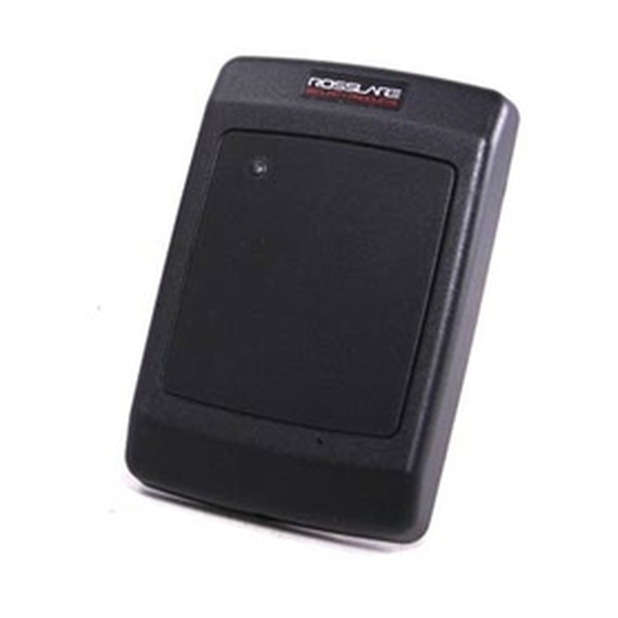
Figure 1: AY-x12C Series
AY-M12C
AY-H12C
2.2
Environmental Characteristics
Specification
AY-M12C AY-H12C AY-L12C AY-K12C AY-Q12C
Operating
Temp. Range
Operating
Humidity Range
2.3
Physical Characteristics
Model
Dimensions
(H x W x D)
AY-M12C
89 x 89 x 15 mm
(3.5 x 3.5 x 0.6 in.)
AY-H12C
110 x 75 x 15 mm
(4.3 x 3.0 x 0.6 in.)
AY-L12C
145 x 43 x 20 mm
(5.7 x 1.7 x 0.8 in.)
AY-K12C
80 x 40 x 12.8 mm
(3.2 x 1.6 x 0.5 in.)
AY-Q12C
120 x 76 x 20 mm
(4.7 x 3.0 x 0.8 in.)
5. Wire the reader to the host as described in Section 4. A linear type
power supply is recommended.
6. Refer to Figure 2 for correct use of mounting screws.
Figure 2: Correct Use of Mounting Screws
1
AY-L12C AY-K12C
AY-Q12C
-31°C to 63°C (-25°F to 145°F)
0 to 95% (non-condensing)
Weight
109 g
(3.9 oz.)
100 g
(3.5 oz)
116 g
(4.1 oz)
70.5 g
(2.5 oz)
480 g
(17.0 oz)
Advertisement
Table of Contents

Related Manuals for Rosslare AY-H12C


Summary of Contents for Rosslare AY-H12C
-
Page 1: Installation Manual
80 x 40 x 12.8 mm 70.5 g (3.2 x 1.6 x 0.5 in.) (2.5 oz) * Measured using a Rosslare proximity card or equivalent. Range also depends on installation environment, reader voltage, and proximity to metal. AY-Q12C 120 x 76 x 20 mm 480 g (4.7 x 3.0 x 0.8 in.) -
Page 2: Operation Instructions
4. Wiring The AY-x12C is supplied with a 10-conductor 18” pigtail. Table 1: Wiring To connect the reader to the controller: Wire Color Function 1. Prepare the reader cable by cutting its jacket back about 3 cm 5–16 VDC (1¼") and strip the insulation from the wires about 1.2 cm (½"). Black Ground 2. -
Page 3: Declaration Of Conformity
Consult the dealer or an experienced radio/TV technician for help. Limited Warranty The full ROSSLARE Limited Warranty Statement is available in the Quick Links section on the ROSSLARE website at www.rosslaresecurity.com. Rosslare considers any use of this product as agreement to the Warranty Terms even if you do not review them.
Need help?
Do you have a question about the AY-H12C and is the answer not in the manual?
Questions and answers