Table of Contents
Advertisement
Quick Links
Advertisement
Table of Contents

Subscribe to Our Youtube Channel
Summary of Contents for Satimo EME Guard
- Page 1 User Manual > EME GUARD Personal exposure meter...
- Page 2 USER MANUAL Reference : SATIMO Bretagne Zone du Vernis 225 rue Rivoalon EME Guard 29200 Brest, FRANCE Tél. : +33 (0) 2.98.05.13.34 Fax. : +33 (0) 2.98.05.53.87 PERSONAL EXPOSURE METER EME Guard Dosimeter equipped with an alarm system to guarantee the safety of people working in strong fields.
- Page 3 European directive 2004/40/EC. The EME Guard can be worn on a belt or strapped across the body and has been designed to fulfil the following requirements: detect the presence of electromagnetic fields,...
- Page 4 WARNING SAFETY MEASURES The safety measures concerning the use of field monitors are as follows : never touch sources of electricity, not even with your field monitor. respect the safety measures stipulated by the equipment operator or original equipment manufacturer. respect the operating instructions and recommendations for equipment which generates, emits or uses electromagnetic energy.
- Page 5 CONTACTS For any questions or suggestions about this product and/or its use, contact your local supplier or our after sales service, specifying the type of product and its serial number. SATIMO Bretagne Zone du Vernis 225 rue Rivoalon 29200 Brest, FRANCE...
-
Page 6: Declaration Of Conformity
Declaration of Conformity SATIMO hereby declare that the product defined below, to which this declaration of conformity belongs, adheres to the following clause and conforms to the Standards and other Normative Documents listed below: • 73/23/EEC, The Low Voltage Directive (safety). -
Page 7: Table Of Contents
NTERPRETATION PERATIONS IGHTS ______________________________________________________ 14 ECHARGING ATTERY 2.6.1 Precautions for Use.____________________________________________________________ 14 2.6.2 How to Recharge the EME Guard Battery ___________________________________________ 15 EME GUARD ANALYSIS V2.0: USE _______________________________________________ 16 _______________________________________________________ 16 UNNING OFTWARE __________________________________________________ 17 OGGING DMINISTRATOR ___________________________________________________ 18 ONFIGURING OSIMETER 3.3.1... -
Page 8: Introducing The Eme Guard
HE TRANSPORT CASE Figure 1 : Case Presentation The transport case includes the EME Guard dosimeter, the battery charger and its power supply cable, the USB cable to connect the measuring device to a PC, the user manual and the EME Guard Analysis V2 software CD. -
Page 9: The Dosimeter
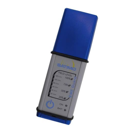
Reference threshold Relative field levels (in V/m) Power On light On/Off button Low Battery warning light Figure 2 : user interface of the EME Guard 8 / 37... - Page 10 So that the EME Guard can be « worn » it is equipped with a two-part clip belt; a belt clip which slides onto a stud situated on the back of the device. Slide the stud horizontally into the Pivot the dosimeter downwards.
-
Page 11: Technical Characteristics
ECHNICAL HARACTERISTICS ➊ Technical characteristics Frequency range 27 MHz – 40 GHz Upper detection limit 200 V/m Lower detection limit 5 V/m ➋ Measurement uncertainty Axial isotropy +/- 1 dB at 1400 MHz +/- 2 dB at 2100 MHz Frequency response 27 MHz - 2.5 GHz : +/- 3 dB 2.5 GHz - 6 GHz : + 6/0 dB 6 GHz - 10 GHz : + 12/+ 6 dB... -
Page 12: Operating The Dosimeter
OPERATING THE DOSIMETER ARAMETERS The different configurable parameters and thus the EME Guard Dosimeter can be adapted to suit the needs of each user, through the EME Guard Analysis Software. How to configure these parameters is explained in detail in the paragraph 3.3... -
Page 13: Recording Measurements
2.1.3 Recording Measurements The EME Guard has a measurement recording function which can be activated or de- activated with the help of the EME Guard Analysis V2.0 Software The non-volatile internal memory enables a maximum number of 30,000 measurement points (each measurement is time/date-stamped). -
Page 14: Estimation Of Remaining Autonomy
2.2.2 Estimation of Remaining Autonomy The field level lights (25%, 50%, 75% and 100% lights ) enable the display of an estimation of remaining power autonomy. Display of Estimated Remaining Electric Autonomy >54 hours >72 hours >18 hours >36 hours If the battery power is insufficient give accurate... -
Page 15: Stopping The Device
TOPPING THE EVICE The dosimeter can be switched off at any moment by pressing the ON / OFF button. The button must be depressed for one or two seconds until the ON light switches off. This is so that if the button is pressed accidentally the device will not be switched off. 3 audio beeps are emitted, indicating that the device is switching off. -
Page 16: How To Recharge The Eme Guard Battery
The charger is equipped with an interchangeable jack. Do not remove this jack or modify the initial set up. In case of doubt, contact our after sales service. 2.6.2 How to Recharge the EME Guard Battery Switch off the device... -
Page 17: Eme Guard Analysis V2.0: Use
Guard Analysis V2.0 folder in the menu All Programs. Or select EME Guard Analysis.exe situated in the software installation folder. When running EME Guard Analysis V2.0 for the first time, the operational language can be chosen (French or English). The following window appears: Figure 4 : Opening screen of EME Guard Analysis V2.0 software (choice of language). -
Page 18: Logging I N A S Administrator
Figure 5 : Main screen of the EME Guard Analysis V2.0 software This screen enables four functions: Configure: to configure the dosimeter using a USB connection. Import: to transfer the measurements recorded in the dosimeter’s internal memory using a USB connection. -
Page 19: Configuring The Dosimeter
Configure. Warning! After any new configuration, the EME Guard is ready to start a new cycle of measurement recordings. Before starting a new measurement cycle, make sure the data recorded during the previous measurement cycle have been correctly downloaded onto your computer. - Page 20 Configure, the following message appears: After Figure 10 : Warning message concerning EME Guard configuration and the transfer of data By clicking on Continue, the COM port number enabling communication is automatically detected. The user is asked to wait while communication is reopening and the configuration is reloading.
-
Page 21: Configuring A Recording Cycle
Figure 12 : Battery level too low – warning message 3.3.1 Configuring a recording cycle The administrator can activate or de-activate the recording cycle. Figure 13 : Recording cycle off Figure 14 : Recording cycle on Recording period: time in seconds between two consecutive recordings. This time must be between 1 second and 255 seconds. -
Page 22: Configuring The Alarms
The Recall current configuration button enables the reading at any time of the measurements recorded in the dosimeter. The Apply new configuration button enables the new configuration to be validated and the new parameters to be transferred to the dosimeter. 3.3.2 Configuring the Alarms The Alarms tab enables the information relative to the alarms to be read and configured. -
Page 23: Configurating Date And Time
General: The General text boxes enable the name of the operator and the place of measurement to be recorded. Commentaries: The Commentaries text boxes enable additional information to be entered. Recall current configuration: this button enables information on the dosimeter to be reread at any moment. -
Page 24: Validating The Configuration
3.3.5 Validating the Configuration When all the fields have been completed, click on OK at the bottom of the window to validate the configuration of the dosimeter. After several seconds a dialog box appears. Figure 19 : Dialog box after successful configuration RANSFER ECORDED The measurement transfer enables the last measurement cycle of the dosimeter to be... - Page 25 The following screen appears: Figure 21 : Measurement transfer screen during data importation. Port number: the port number indicates the communication port used. CANCEL: enables importation to be stopped at any moment and the measurement import screen to be closed. The progression bar indicates the percentage of imported measurements downloaded.
- Page 26 Click on the Load button to display the file selection window. Select a measurement file « .bin » (or « .mes » for measurements taken using the V1 version of the EME Guard Analysis software). By clicking on OK, the measures displayed are in V/m by default in the main window.
-
Page 27: Information On The Measurements
By default, the graph shows the pattern of field measurements over time (instantaneous field measurements made by the device), and thus the pattern of mean field values calculated over the six last minutes of measurement (value calculated by EME Guard Analysis software using those instantaneous measurements). Any interruptions to the measurement cycle are indicated by a blue circle on the graph. - Page 28 To display Instantaneous measurement, Mean 6mn Measurement and Display Interruption, select the appropriate checkbox under the graph. The different checkboxes situated in the Graph Selection dialog box enable the display of the mean (Mean) the maximum (Max) and the minimum (Min) field measurement values, as well as the reference threshold value (Threshold) and the thresholds for the audio alarm (Buzzer) and vibrator alarm (Vibrator) used during measurement.
- Page 29 Figure 27 : Selection of Zoom zone Release the mouse. The graph shows the field values between the two selected samples. Figure 28 : Monitoring Graph after Zoom All the display functions described for a graph in normal mode are also available in zoom mode.
-
Page 30: Statistical Field Measurement Display
3.5.3 Statistical field measurement display. The Statistics tab shows the statistical data relevant to the loaded measurement file. Figure 30 : statistical field data over time To the right of this graph two values have been calculated: Mean: mean value of field variation over time. Standard Deviation: standard deviation of this variation. -
Page 31: Battery Monitoring Screen
3.5.4 Battery Monitoring Screen The Battery Voltage Evolution tab enables the battery voltage over the measurement cycle to be monitored. The following graph is displayed: Figure 32 : Battery monitoring screen In this window a red line indicates battery voltage level over time. To the right of the graph two numerical values are displayed. -
Page 32: Information Display
3.5.6 Information Display The Information tab enables the display of information relevant to the measurement. The following dialog box is displayed: Figure 34 : Information display This is the information entered by the administrator when configuring the device before the measurement cycle. No information can be entered in this dialog box. - Page 33 Figure 35 : Excel report of measurement file This Excel report facilitates information processing, graph creation, printing and the calculation of complex functions. Creation of Excel File: Open the measurement file and select File Report Excel Report. This opens the Windows save file window.
-
Page 34: Creation Of A Text Report
3.5.8 Creation of a Text Report NotePad is required for this operation It is possible to create a file in text format from a measurement file. The text file also enables access to the information contained in the measurement file: Serial Number and calibration dates of the dosimeter which made the measurements. -
Page 35: Menus
ENUS The EME Guard Analysis measurement software proposes different menus to obtain and help and information on its use. 3.6.1 File Menu Figure 37 : File Menu Load: like the Load button on the main interface, enables the measurement file to be loaded. -
Page 36: Unit Menu
3.6.4 EME Guard Menu Only the administrator can access the submenus Configure and Read the calibration dates in the EME Guard menu. Figure 40 : EME Guard Menu Configure: like the Configure button on the main interface, enables the dosimeter to be configured (measurement recording cycle, alarms, information, date and time). -
Page 37: Help Menu
3.6.5 Help Menu Figure 43 : Help Menu About EME Guard Analysis: provides information on the software version and the contact details of the company SATIMO. Figure 44 : Software information screen User manual: enables access to the EME Guard Analysis V2 user manual. - Page 38 Figure 45 : Information graph on the subject of ICNRP values Information on the calculation of the mean value over 6 minutes: when selected from the menu, the following dialog box is displayed: Figure 46 : Information on the subject of mean field calculation 37 / 37...
- Page 40 RF Safety Product Center SATIMO Bretagne Technopole Brest Iroise Z.I. du Vernis 225 rue Pierre Rivoalon 29200 Brest, FRANCE Tel: +33 (0)2 98 05 13 34 Fax: + 33 (0)2 98 05 53 87 hotline.rf-safety@satimo.fr www.satimo.com...
Need help?
Do you have a question about the EME Guard and is the answer not in the manual?
Questions and answers