Table of Contents
Advertisement
Quick Links
Advertisement
Table of Contents

Subscribe to Our Youtube Channel
Related Manuals for FLIR GFx320


Summary of Contents for FLIR GFx320
- Page 1 User’s manual FLIR GFx3xx series...
- Page 4 Important note Before operating the device, you must read, understand, and follow all instructions, warnings, cautions, and legal disclaimers. Důležitá poznámka Před použitím zařízení si přečtěte veškeré pokyny, upozornění, varování a vyvázání se ze záruky, ujistěte se, že jim rozumíte, a řiďte se jimi.
- Page 5 User’s manual FLIR GFx3xx series #T810169; r. AN/42241/42268; en-US...
-
Page 7: Table Of Contents
Conditions of Use for Ex Equipment ..........15 Important note about training and applications ........16 General ................16 Important information about FLIR GFx3xx series service ..... 17 List of accessories and services ............18 Introduction ..................21 Example images ................22 10.1... - Page 8 Table of contents 13.2 Figure .................. 32 13.3 Related topics ................ 33 Camera parts .................. 34 14.1 View from the left ..............34 14.1.1 Figure ................ 34 14.1.2 Explanation..............34 14.2 View from the right ..............35 14.2.1 Figure ................ 35 14.2.2 Explanation..............
- Page 9 Table of contents 16.5 Selecting a suitable color palette ..........46 16.5.1 Procedure ..............46 16.6 Enabling or disabling histogram mode ......... 46 16.6.1 General..............46 16.6.2 Procedure ..............46 16.7 Enabling or disabling inverted color palette ........46 16.7.1 Procedure ..............46 16.8 Changing object parameters .............
- Page 10 Table of contents 18.12.1 Figure ................ 58 18.12.2 Procedure ..............58 18.13 Laser warning label ..............58 18.14 Laser rules and regulations ............58 18.15 Assigning functions to the programmable button ......59 18.15.1 General..............59 18.15.2 Procedure ..............59 Working with views and images............
- Page 11 Detectable gases................106 37.1 General ................106 37.2 Gases that can be detected by FLIR GFx3xx ......106 Why do some gases absorb infrared energy? ........109 About FLIR Systems ..............112 39.1 More than just an infrared camera ..........113 39.2...
- Page 12 Table of contents History of infrared technology............125 Theory of thermography..............128 44.1 Introduction ................. 128 44.2 The electromagnetic spectrum..........128 44.3 Blackbody radiation............... 128 44.3.1 Planck’s law .............. 129 44.3.2 Wien’s displacement law..........130 44.3.3 Stefan-Boltzmann's law ..........131 44.3.4 Non-blackbody emitters..........
-
Page 13: Disclaimers
Products which are not manufactured by FLIR Systems but included in systems deliv- ered by FLIR Systems to the original purchaser, carry the warranty, if any, of the particu- lar supplier only. FLIR Systems has no responsibility whatsoever for such products. -
Page 14: Quality Assurance
1.6 EULA Terms • You have acquired a device (“INFRARED CAMERA”) that includes software licensed by FLIR Systems AB from Microsoft Licensing, GP or its affiliates (“MS”). Those in- stalled software products of MS origin, as well as associated media, printed materials, and “online”... -
Page 15: Eula Terms
MERCHANTABILITY or FITNESS FOR A PARTICULAR PURPOSE. See the GNU Lesser General Public License, http://www.gnu.org/licenses/lgpl-2.1.html. The source code for the libraries Qt4 Core and Qt4 GUI may be requested from FLIR Systems AB. #T810169; r. AN/42241/42268; en-US... -
Page 16: Safety Information
WARNING Do not take the following items (that FLIR Systems supplies) into a classified (hazardous) area. An ex- plosion can occur. This can cause injury or death to persons and damage to the equipment. -
Page 17: General Cautions And Warnings
Safety information CAUTION Only use the camera with a battery that has the item part number T199183 on it (that FLIR Systems supplies). If you do not obey this, damage to the equipment can occur and the protection that the equip- ment gives can become unsatisfactory. - Page 18 Applicability: Cameras with one or more batteries. Do not attach the batteries directly to a car’s cigarette lighter socket, unless FLIR Systems supplies a specific adapter to connect the batteries to a cigarette lighter socket. Damage to the batteries can occur.
- Page 19 Safety information CAUTION Applicability: Cameras with one or more batteries. Do not make holes in the battery with objects. Damage to the battery can occur. CAUTION Applicability: Cameras with one or more batteries. Do not hit the battery with a hammer. Damage to the battery can occur. CAUTION Applicability: Cameras with one or more batteries.
-
Page 20: Table Of Entity Parameters
Safety information CAUTION Applicability: Cameras with one or more batteries. When the battery is worn, apply insulation to the terminals with adhesive tape or equivalent materials before you discard it. Damage to the battery and injury to persons can occur if you do not do this. CAUTION Applicability: Cameras with one or more batteries. -
Page 21: Laser Warning Label
Safety information 2.2.3 Laser warning label A laser warning label with the following information is affixed to the camera: 2.2.4 Laser rules and regulations Wavelength: 635 nm. Maximum output power: 1 mW. This product complies with 21 CFR 1040.10 and 1040.11 except for deviations pursuant to Laser Notice No. -
Page 22: Applicable Markings
Safety information 6. Equipment Protection Level (EPL): EPL is linked to the intended use and zones. Gc is linked to Gas Group II, Zone 2 and constitutes minimum protection level of either n, ic or pz. 7. Equipment Group: Group I = Mines, Group II = Other. 8. -
Page 23: Notice To User
As with most electronic products, this equipment must be disposed of in an environmen- tally friendly way, and in accordance with existing regulations for electronic waste. Please contact your FLIR Systems representative for more details. 3.5 Training To read about infrared training, visit: •... -
Page 24: Note About Authoritative Versions
Notice to user 3.7 Note about authoritative versions The authoritative version of this publication is English. In the event of divergences due to translation errors, the English text has precedence. Any late changes are first implemented in English. #T810169; r. AN/42241/42268; en-US... -
Page 25: Customer Help
• The communication protocol, or method, between the camera and your device (for ex- ample, SD card reader, HDMI, Ethernet, USB, or FireWire) • Device type (PC/Mac/iPhone/iPad/Android device, etc.) • Version of any programs from FLIR Systems #T810169; r. AN/42241/42268; en-US... -
Page 26: Downloads
Customer help • Full name, publication number, and revision number of the manual 4.3 Downloads On the customer help site you can also download the following, when applicable for the product: • Firmware updates for your infrared camera. • Program updates for your PC/Mac software. •... -
Page 27: Conditions Of Use For Ex Equipment
CAUTION Only use the camera with a battery that has the item part number T199183 on it (that FLIR Systems supplies). If you do not obey this, damage to the equipment can occur and the protection that the equip- ment gives can become unsatisfactory. -
Page 28: Important Note About Training And Applications
Important note about training and applications 6.1 General Infrared inspection of gas leaks, furnaces, and high-temperature applications—including infrared image and other data acquisition, analysis, diagnosis, prognosis, and reporting —is a highly advanced skill. It requires professional knowledge of thermography and its applications, and is, in some countries, subject to certification and legislation. -
Page 29: Important Information About Flir Gfx3Xx Series Service
Important information about FLIR GFx3xx series service • Service must only be performed by an authorized FLIR service department. • Contact the service department before shipping the camera. Many problems can be resolved on the phone—if so, the camera does not need to be shipped. -
Page 30: List Of Accessories And Services
(hazardous) area. An explosion can occur. An explosion can cause death or injury to persons and damage to the equipment. FLIR IR Camera Player DSW-10000 FLIR Reporter Profes- T198586 sional (license only) FLIR ResearchIR Max T198697 + HSDR 4 (hardware sec. - Page 31 FLIR ResearchIR T199012 Standard 4 (printed li- cense key) FLIR ResearchIR T199042 Standard 4 Upgrade (printed license key) FLIR Tools T198584 FLIR Tools+ (download T198583 card incl. license key) FLIR VideoReport T198585 Hand strap T129728 T129728ACC Hard transport case T199466...
- Page 32 Note FLIR Systems reserves the right to discontinue models, parts or accessories, and other items, or to change specifications at any time without prior notice. #T810169; r. AN/42241/42268; en-US...
-
Page 33: Introduction
Introduction Thank you for choosing a FLIR GFx3xx series camera from FLIR Systems. The FLIR GFx3xx series camera is an infrared camera for optical gas imaging (OGI) in explosive atmospheres that visualizes and pinpoints leaks of methane and other volatile organic compounds (VOCs), without the need to shut down the operation. -
Page 34: Example Images
Example images 10.1 General This section contains example images from various applications. Note Gas leaks are easier to see in live image mode, which is the reason the leaks are indicated with a red dot in the images below. 10.2 Images #T810169;... -
Page 35: Quick Start Guide
The code is based on the serial number of the camera. To get the camera unique code, you must log in with a FLIR Customer Support account and register the camera. If you already have an existing FLIR Customer Support account, you can use the same login credentials. - Page 36 Quick start guide 8. To log in with your existing FLIR Customer Support account, do the following: 8.1. Enter your Username and Password. 8.2. Click Log In. 9. To create a new FLIR Customer Support account, do the following: 9.1.
- Page 37 Quick start guide 11. On the computer, enter the serial number of the camera and click Validate. 12. When the serial number is validated, click Continue. #T810169; r. AN/42241/42268; en-US...
- Page 38 14. When the registration is completed, the four-digit code is displayed. Note • The code is also sent by e-mail to the address registered with your FLIR Customer Support account. • The code is also displayed in your FLIR Customer Support portal under My Stuff >...
-
Page 39: Detecting A Gas Leak
Quick start guide 15. On the camera, do the following to enter the code: • Move the joystick up/down to select a digit. • Move the joystick left/right to navigate to the previous/next digit. • When all digits have been entered, move the joystick right to select . -
Page 40: Related Topics
Quick start guide 7. Wait until the cooling procedure is completed. Then turn the mode wheel to enter video mode. 8. Push the temperature range button, then do the following: 8.1. Move the joystick up/down to choose a suitable temperature range for your object. -
Page 41: Related Topics
Quick start guide 5. Close the cover and tighten the Torx T20 screw to 80 N cm. 6. Push the button to turn on the camera. A mechanical cooler will begin cooling down the infrared detector. A test image and a progress bar are displayed during cool-down. - Page 42 Quick start guide • 20.1 Laying out a measurement tool, page 63 • 19.1 Saving infrared images, page 60 #T810169; r. AN/42241/42268; en-US...
-
Page 43: Flir Gfx3Xx Series General Instrument Check
FLIR GFx3xx series general instrument check The following general instrument check process ensures that the camera can detect the intended gas compounds with the same sensitivity as when originally manufactured. 1. Make sure that the camera powers on. 2. Make sure that the camera completes the cool-down process and produces a live in- frared image. -
Page 44: Note About Ergonomics
A note about ergonomics 13.1 General To prevent overstrain injuries, it is important that you hold the camera ergonomically cor- rect. This section gives advice and examples on how to hold the camera. Note Please note the following: • Always tilt the viewfinder to fit your work position. •... -
Page 45: Related Topics
A note about ergonomics 13.3 Related topics • 18.5 Adjusting the viewing angle of the viewfinder, page 54 • 18.7 Adjusting the camera grip, page 55 • 18.9 Adjusting the viewing angle of the display, page 56 #T810169; r. AN/42241/42268; en-US... -
Page 46: Camera Parts
Camera parts 14.1 View from the left 14.1.1 Figure 14.1.2 Explanation 1. Programmable button for one of the following functions: • Change the zoom factor. • Hide/show graphics. • Change the polarity. • Change the palette. You program the button in setup mode in the Preferences tab. -
Page 47: View From The Right
Camera parts 14.2 View from the right 14.2.1 Figure 14.2.2 Explanation 1. Camera handle. 2. Digital camera lamp. When you are in digital camera mode, you turn on the lamps by pushing the joystick. 3. Digital video camera. 4. Laser pointer. 5. -
Page 48: View From The Rear
Camera parts 7. A/M button (Auto/Manual). Function: • Push and release the button to change the image adjustment method between Au- to, Manual, and HSM. • Push and hold down the button for more than 1 second to perform a non-uniform- ity correction (NUC). -
Page 49: View From The Rear With Open Cover
Camera parts button (On/off). Function: • To turn on the camera, push and release the button. • To turn off the camera, push and hold the button until the progress bar that is dis- played on the screen reaches the end. 6. -
Page 50: Battery Condition Led Indicator
Camera parts CAUTION Only use the camera with a battery that has the item part number T199183 on it (that FLIR Systems supplies). If you do not obey this, damage to the equipment can occur and the protection that the equip- ment gives can become unsatisfactory. -
Page 51: Laser Pointer
Camera parts 14.7 Laser pointer 14.7.1 General The camera has a laser pointer. When the laser pointer is on, you will see a laser dot ap- proximately at the target. 14.7.2 Figure This figure shows the difference in position between the laser pointer and the optical cen- ter of the infrared lens. -
Page 52: Serial Number
Camera parts 14.8 Serial number 14.8.1 General The serial number of the camera is provided on a label in the battery compartment. 14.8.2 Figure #T810169; r. AN/42241/42268; en-US... -
Page 53: Screen Elements
Screen elements 15.1 Mode selector Note To select the mode, turn the mode wheel on the left side of the camera. 15.1.1 Figure 15.1.2 Explanation 1. Camera mode. 2. Video mode: Record video clips (*.mp4) and video sequences (*.seq). 3. Archive mode: View saved images and video sequences. 4. -
Page 54: Figure
Screen elements 15.3.1 Figure 15.3.2 Explanation 1. Menu tab. 2. Mode indicator. 3. Menu tab name. 4. Menu item. 5. Status indicators: • Time. • Date. • GPS indicator. • USB indicator. • Power indicator. • Memory card indicator. The indicator shows the amount of free space on the memory card. -
Page 55: Achieving A Good Image
Achieving a good image 16.1 General A good image depends on several different settings, although some settings affect the image more than other. These are the settings you need to experiment with: • Adjusting the infrared camera focus. • Adjusting the image, using Auto, Manual, or HSM (= High Sensitivity Mode). •... -
Page 56: Explanation Of The Adjustment Methods
Achieving a good image 16.3.2 Explanation of the adjustment methods Auto An adjustment method that will automatically adjust the image for best brightness and contrast. HSM = High Sensitivity Mode. An adjustment method that is specifically designed for gas detection applications. Working in this mode, you can change the sensitivity to optimize the image quality. -
Page 57: Understanding The Temperature Scale
Achieving a good image 16.4.1.2 Types of temperature ranges Type Example Explanation Name All temperatures the Characteristic tempera- –40°C to +350°C (–40° ture range F to +662°F) camera can register. This range is the total sum of the temperature ranges (type no. 2 below). -
Page 58: Changing The Temperature Range
Achieving a good image 16.4.3 Changing the temperature range 16.4.3.1 Procedure Follow this procedure to change the temperature range: 1. Do one of the following: • Push the temperature range button on the left side of the camera. • Push the button, then select Adjust temp. -
Page 59: Changing Object Parameters
Achieving a good image 4. Move the joystick up/down to go to select Invert palette. 5. Push the joystick to enable/disable the setting. 6. Push the button to leave the setup mode. 16.8 Changing object parameters 16.8.1 General For accurate measurements, you must set the object parameters. You can do this locally or globally. -
Page 60: Related Topics
Achieving a good image 8. Push the button to confirm and leave the setup mode. Note • Of the seven parameters above, emissivity and reflected apparent temperature are the two most important to set correctly in the camera. • To change object parameters locally, first select a measurement tool in the toolbox, then select Use local parameters. -
Page 61: Connecting External Devices
Connecting external devices 17.1 General You can connect the following external devices to the camera: • A video monitor or projector, connected using an HDMI cable. • A computer, to move images and other files to and from the camera. •... - Page 62 Connecting external devices 2. In Windows Explorer, select My Computer and right-click the memory card. 3. Select Format. 4. Under File system, select FAT. 5. Click Start. Note • SDHC memory cards that are 4 GB or larger can only be formatted to the FAT32 file system.
-
Page 63: Handling The Camera
Handling the camera 18.1 Charging the camera battery WARNING Make sure that you install the socket-outlet near the equipment and that it is easy to get access to. Note • You must charge the battery for 4 hours before starting the camera for the first time. After that, you must charge the battery whenever a warning message for low battery power is displayed on the screen. -
Page 64: Installing And Removing The Camera Battery
Handling the camera 18.2 Installing and removing the camera battery 18.2.1 Installing the battery Note Use a clean, dry cloth to remove any water or moisture on the battery before you install it. 18.2.1.1 Procedure Follow this procedure: 1. Before operating the camera, you must read, understand, and follow the warnings, cautions, and notes in sections , page and 5 Conditions of Use for Ex Equipment, page 15. -
Page 65: Turning On The Camera
Handling the camera 3. Unscrew the Torx T20 screw and open the battery compartment cover. 4. Push the release button for the battery. 5. Pull out the battery from the battery compartment. 18.3 Turning on the camera 18.3.1 Procedure To turn on the camera, push and release the button. -
Page 66: Adjusting The Viewing Angle Of The Viewfinder
Handling the camera 18.5 Adjusting the viewing angle of the viewfinder 18.5.1 General To make your working position as comfortable as possible, you can adjust the viewing angle of the viewfinder. 18.5.2 Figure 18.5.3 Procedure To adjust the viewfinder, tilt the viewfinder up or down. 18.6 Adjusting the viewfinder’s dioptric correction 18.6.1 General... -
Page 67: Procedure
Handling the camera 18.6.3 Procedure To adjust the viewfinder’s dioptric correction, look at the displayed text or graphics on the screen and rotate the adjustment knob clockwise or counter-clockwise for best sharpness. Note • Maximum dioptric correction: +2 • Minimum dioptric correction: –2 18.7 Adjusting the camera grip 18.7.1 General To make your working position as comfortable as possible, you can adjust the angle of... -
Page 68: Adjusting The Viewing Angle Of The Display
Handling the camera 18.9 Adjusting the viewing angle of the display 18.9.1 General To make your working position as comfortable as possible, you can adjust the viewing angle of the display. 18.9.2 Figure 18.9.3 Procedure To adjust the viewing angle of the display, rotate the display clockwise or counter- clockwise. -
Page 69: Procedure
Handling the camera 18.10.2 Procedure Do one of the following: • For far focus, rotate the focus ring counter-clockwise (looking at the front of the lens) • For near focus, rotate the focus ring clock-wise (looking at the front of the lens) 18.11 Using the zoom function 18.11.1 General You can zoom in on infrared images in preview or archive mode. -
Page 70: Operating The Laser Pointer
Handling the camera 18.12 Operating the laser pointer 18.12.1 Figure 18.12.2 Procedure Follow this procedure to operate the laser pointer: 1. To turn on the laser pointer, push and hold the laser button. 2. To turn off the laser pointer, release the laser button. WARNING Do not look directly into the laser beam. -
Page 71: Assigning Functions To The Programmable Button
Handling the camera 18.15 Assigning functions to the programmable button 18.15.1 General The camera has a programmable button. You can assign one of the following functions to the programmable button: • Change the zoom factor. • Hide/show graphics. • Change the polarity. •... -
Page 72: Working With Views And Images
Working with views and images 19.1 Saving infrared images 19.1.1 General You can save one or more images to an SD Memory Card. 19.1.2 Image capacity The approximate number of images that can be saved on an SD Memory Card is 2,000 per GB. -
Page 73: Opening An Image
Working with views and images 19.2 Opening an image 19.2.1 General When you save an image, you store the image on an SD Memory Card. To display the image again, you can open it from the SD Memory Card. 19.2.2 Procedure Follow this procedure to open an image: 1. -
Page 74: Editing A Saved Image
Working with views and images 6. Push the button to leave the setup mode. 19.4 Editing a saved image 19.4.1 General You can edit a saved image. You can do one or more of the following tasks: • Edit measurements. •... -
Page 75: Working With Measurement Tools
Working with measurement tools 20.1 Laying out a measurement tool 20.1.1 General To measure a temperature, you use one or several measurement tools, such as a spot- meter, a box, etc. 20.1.2 Procedure Follow this procedure to lay out measurement tool: 1. -
Page 76: Changing Object Parameters
Working with measurement tools Follow this procedure to create and set up a difference calculation: 1. Turn the mode wheel to 2. Push the button to display a menu. 3. Move the joystick left/right to go to the Edit tab. 4. -
Page 77: Recommended Values
Working with measurement tools • External optics transmission, i.e., the optical transmission of any protective windows, etc. that are set up between the camera and the object of interest. 20.4.3 Recommended values If you are unsure about the values, the following values are recommended: Emissivity 0.95 Distance... -
Page 78: Programming The Camera
Programming the camera 21.1 General You can program the camera to save images periodically. 21.2 Procedure Follow this procedure to make the camera save images periodically: 1. Turn the mode wheel to . This will display the following dialog box: 2. -
Page 79: Recording Video Clips
(*.seq). In this mode, the camera can be regarded as an ordinary digital vid- eo camera. The video clips can be edited and played back in FLIR VideoReport. *.seq video clips can also be handled and edited in FLIR Reporter. -
Page 80: Changing Settings
Changing settings 23.1 General You can change a variety of settings for the camera: • Regional settings, such as language, date, time, etc. • Camera settings, such as digital camera color, display intensity, etc. • Preferences, such as user-configurable buttons, image overlay information, text size, etc. -
Page 81: Technical Data
24.2 Note about technical data FLIR Systems reserves the right to change specifications at any time without prior notice. Please check http://support.flir.com for latest changes. -
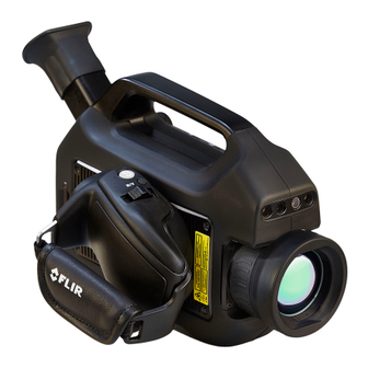
Page 82: Flir Gfx320 14.5° Fixed Lens
The FLIR GFx320 is used in industrial settings such as oil refineries, natural gas processing plants, off- shore platforms, chemical/petrochemical industries, and biogas and power generation plants. - Page 83 Technical data Image presentation Display Built-in widescreen, 4.3 in. LCD, 800 × 480 pixels Viewfinder Built-in, tiltable OLED, 800 × 480 pixels Automatic image adjustment Continuous/manual; linear or histogram based Manual image adjustment Level/span Image presentation modes Image modes IR image, visual image, high sensitivity mode (HSM) Measurement Temperature range...
- Page 84 Video streaming Radiometric IR video streaming Full dynamic to PC using USB cable. PC software capable of displaying the video stream include the following: • FLIR IR Camera Player • FLIR ResearchIR • FLIR Tools Non-radiometric IR video streaming RTP/MPEG4...
- Page 85 Technical data Power system External power operation AC adapter 90–260 VAC, 50/60 Hz or 12 V from a vehicle (cable with standard plug, optional) DC operation 8 to 15.3 V DC, polarity protected (proprietary protected) Power 8.5 W typically Start-up time Typically 7 min.
- Page 86 Technical data Certifications Compliance • ATEX/IECEx, Ex ic nC op is IIC T4 Gc II 3 G • ANSI/ISA-12.12.01-2013, Class I Division 2 • CSA 22.2 No. 213, Class I Division 2 Shipping information Packaging, type Cardboard box List of contents •...
-
Page 87: Flir Gfx320 24° Fixed Lens
The FLIR GFx320 is used in industrial settings such as oil refineries, natural gas processing plants, off- shore platforms, chemical/petrochemical industries, and biogas and power generation plants. - Page 88 Technical data Image presentation Display Built-in widescreen, 4.3 in. LCD, 800 × 480 pixels Viewfinder Built-in, tiltable OLED, 800 × 480 pixels Automatic image adjustment Continuous/manual; linear or histogram based Manual image adjustment Level/span Image presentation modes Image modes IR image, visual image, high sensitivity mode (HSM) Measurement Temperature range...
- Page 89 Video streaming Radiometric IR video streaming Full dynamic to PC using USB cable. PC software capable of displaying the video stream include the following: • FLIR IR Camera Player • FLIR ResearchIR • FLIR Tools Non-radiometric IR video streaming RTP/MPEG4...
- Page 90 Technical data Power system External power operation AC adapter 90–260 VAC, 50/60 Hz or 12 V from a vehicle (cable with standard plug, optional) DC operation 8 to 15.3 V DC, polarity protected (proprietary protected) Power 8.5 W typically Start-up time Typically 7 min.
- Page 91 Technical data Certifications Compliance • ATEX/IECEx, Ex ic nC op is IIC T4 Gc II 3 G • ANSI/ISA-12.12.01-2013, Class I Division 2 • CSA 22.2 No. 213, Class I Division 2 Shipping information Packaging, type Cardboard box List of contents •...
-
Page 92: Mechanical Drawings
Mechanical drawings [See next page] #T810169; r. AN/42241/42268; en-US... -
Page 95: Eu Declaration Of Conformity
EU Declaration of conformity [See next page] #T810169; r. AN/42241/42268; en-US... -
Page 97: Met Compliance Data Report (Truncated)
MET Compliance Data Report (truncated) [See next page] #T810169; r. AN/42241/42268; en-US... - Page 98 TEST STANDARD IEC/EN 60079-15 Clause Test 22.5.2 Before Seal Test Voltage Test (Component) 22.5.1 Conditioning (Component) 22.5.3.2 Seal Component Test (Component) Method 3 22.5.3.3 After Seal Test Dielectric Test (Component) Critical Drawings SAFJ TDS-103A Blank Test Data Sheets 6-17-2013 Page 1 of 10 Issued by: Department Manager or designee...
- Page 99 Century Court Tolpits Lane Walford, Herts, UK WD18 9RS Product description: IDCA Component within the FLIR George Camera, Model GFx320. Note: Testing will be with respect to EN/IEC 60079-15:2010 clause 22.5 as this testing is more onerous than ANSI/ISA 12.12.01:2012 and CSA/CAN C22.2 No. 213 (reaffirmed 2013) requirements.
-
Page 100: Iec/Iecee/Intertek Test Report (Truncated)
IEC/IECEE/Intertek Test Report (truncated) [See next page] #T810169; r. AN/42241/42268; en-US... - Page 101 Test Report. Test item description ..... : Infrared Optical Gas Imaging Camera Trade Mark ........: FLIR Manufacturer ........: FLIR Systems AB Model/Type reference ...... : FLIR GFX320 Ratings ..........: 7.2VDC (battery operated), Class III CLASS 2 LASER PRODUCT...
-
Page 103: Iec/Iecee/Intertek Cb Test Certificate
IEC/IECEE/Intertek CB Test Certificate [See next page] #T810169; r. AN/42241/42268; en-US... -
Page 106: Met Laboratories Test Certificate (Truncated)
MET Laboratories Test Certificate (truncated) [See next page] #T810169; r. AN/42241/42268; en-US... - Page 107 914 WEST PATAPSCO AVENUE ! BALTIMORE, MARYLAND 21230-3432 ! PHONE (410) 354-3300 ! FAX (410) 354-3313 FLIR SYSTEMS AB, GFx320 Optical Gas Imaging Camera Tested under ANSI/ISA-12.12.01-2016 Nonincendive Electrical Equipment for Use in Class I and II, Division 2 and Class III, Divisions 1 and 2 Hazardous (Classified) Locations, Seventh Edition C22.2 NO.
-
Page 108: Met Laboratories Letter Of Certification
MET Laboratories Letter of Certification [See next page] #T810169; r. AN/42241/42268; en-US... - Page 109 MET Mark Utilization Agreement or the MET Applicant Contract. The report covering the above stated product is forthcoming. Thank you for the opportunity to perform this service for FLIR Systems AB. We look forward to future opportunities with your company.
-
Page 110: Element Type Examination Certificate (Truncated)
Element Type Examination Certificate (truncated) [See next page] #T810169; r. AN/42241/42268; en-US... - Page 111 Directive 2014/34/EU – Annex VIII Type Examination EMT16ATEX0032X Certificate No.: Product: Optical Gas Imaging Camera, GFx320 Manufacturer: FLIR SYSTEMS AB, Address: Antennvägen 6, SE-187 15 Täby, Sweden This product and any acceptable variation thereto is specified in the schedule to this certificate and the documents therein referred to.
-
Page 112: Iecex Technical Report: Gb/Emt/Extr16.0015/00
IECEx Technical Report: GB/ EMT/ExTR16.0015/00 [See next page] #T810169; r. AN/42241/42268; en-US... - Page 113 IEC 60079-0 (Ed.6.0); IEC 60079-11 (Ed.6.0); IEC 60079-15 (Ed.4); IEC 60079-28 (Ed.2) Issuing ExTL*: EMT - Element Materials Technology Endorsing ExCB*: EMT - Element Materials Technology Manufacturer*: FLIR SYSTEMS AB Antennvägen 6, SE-187 15 Täby, Country of Manufacture*: Sweden Ex Protection*:...
-
Page 114: Iecex Quality Assessment Report: Gb/Emt/Qar16.0003/00
IECEx Quality Assessment Report: GB/EMT/QAR16.0003/00 [See next page] #T810169; r. AN/42241/42268; en-US... - Page 115 Audit Date*: 2016-09-06 (yyyy-mm-dd) Date of Issue*: 2016-10-14 (yyyy-mm-dd) Valid until*: 2019-09-05 (yyyy-mm-dd) Site(s) audited*: FLIR SYSTEMS AB, Antennvägen 6, SE-187 66 Täby, Sweden Issuing ExCB*: EMT - Element Materials Technology Manufacturer*: FLIR SYSTEMS AB, Antennvägen 6, SE-187 66 Täby,...
-
Page 116: Cleaning The Camera
Cleaning the camera 35.1 Camera housing, cables, and other items 35.1.1 Liquids Use one of these liquids: • Warm water • A weak detergent solution 35.1.2 Equipment A soft cloth 35.1.3 Procedure Follow this procedure: 1. Soak the cloth in the liquid. 2. -
Page 117: Cooler Maintenance
36.2 Signs to watch for The FLIR Systems microcooler is equipped with a closed-loop speed regulator, which adjusts the cooler motor speed to regulate the detector temperature. Typically, the cooler runs at maximum speed for 7–10 minutes (depending on model), and then slows to about 40% of maximum speed. -
Page 118: Detectable Gases
Detectable gases 37.1 General The FLIR GFx3xx camera has been engineered and designed to detect various gases, such as hydrocarbons. Within the laboratory, FLIR Systems has tested numerous gases for detection at varying concentrations. 37.2 Gases that can be detected by FLIR... - Page 119 Detectable gases Common name Molecular formula Structural formula Ethylene Heptane Hexane Isoprene m-Xylene Methane Methanol Methyl ethyl ketone #T810169; r. AN/42241/42268; en-US...
- Page 120 Detectable gases Common name Molecular formula Structural formula MIBK Octane Pentane Propane Propylene Toluene #T810169; r. AN/42241/42268; en-US...
-
Page 121: Why Do Some Gases Absorb Infrared Energy
Why do some gases absorb infrared energy? From a simplistic mechanical point of view, molecules in a gas could be compared to weights (the balls in the figures below), connected together via springs. Depending on the number of atoms, their respective size and mass, the elastic constant of the springs, molecules may move in given directions, vibrate along an axis, rotate, twist, stretch, rock, wag, etc. - Page 122 FLIR GFx3xx series cameras take advantage of the absorbing and emitting nature of cer- tain molecules, to visualize them in black or white in their native environments. The gas visualization contrast is a function of the gas concentration multiplied by the path length (CL), the temperature difference between to background (e.g.
- Page 123 Why do some gases absorb infrared energy? Figure 38.8 Sulfur hexafluoride (SF ). Strong absorption around 10.6 μm, CL=50 ppmxm, Source: PNNL #T810169; r. AN/42241/42268; en-US...
-
Page 124: About Flir Systems
• Prox Dynamics (2016) Figure 39.1 Patent documents from the early 1960s FLIR Systems has three manufacturing plants in the United States (Portland, OR, Bos- ton, MA, Santa Barbara, CA) and one in Sweden (Stockholm). Since 2007 there is also a manufacturing plant in Tallinn, Estonia. -
Page 125: More Than Just An Infrared Camera
39.1 More than just an infrared camera At FLIR Systems we recognize that our job is to go beyond just producing the best infra- red camera systems. We are committed to enabling all users of our infrared camera sys- tems to work more productively by providing them with the most powerful camera–... -
Page 126: Supporting Our Customers
About FLIR Systems 39.3 Supporting our customers FLIR Systems operates a worldwide service network to keep your camera running at all times. If you discover a problem with your camera, local service centers have all the equipment and expertise to solve it within the shortest possible time. Therefore, there is no need to send your camera to the other side of the world or to talk to someone who does not speak your language. -
Page 127: Terms, Laws, And Definitions
Terms, laws, and definitions Term Definition Absorption and emission The capacity or ability of an object to absorb incident radi- ated energy is always the same as the capacity to emit its own energy as radiation Apparent temperature uncompensated reading from an infrared instrument, con- taining all radiation incident on the instrument, regardless of its sources Color palette... - Page 128 Terms, laws, and definitions Term Definition Radiative heat transfer Heat transfer by the emission and absorption of thermal radiation Reflected apparent temperature apparent temperature of the environment that is reflected by the target into the IR camera Spatial resolution ability of an IR camera to resolve small objects or details Temperature measure of the average kinetic energy of the molecules and atoms that make up the substance...
-
Page 129: Thermographic Measurement Techniques
Thermographic measurement techniques 41.1 Introduction An infrared camera measures and images the emitted infrared radiation from an object. The fact that radiation is a function of object surface temperature makes it possible for the camera to calculate and display this temperature. However, the radiation measured by the camera does not only depend on the tempera- ture of the object but is also a function of the emissivity. - Page 130 Thermographic measurement techniques 41.2.1.1.1 Method 1: Direct method Follow this procedure: 1. Look for possible reflection sources, considering that the incident angle = reflection angle (a = b). Figure 41.1 1 = Reflection source 2. If the reflection source is a spot source, modify the source by obstructing it using a piece if cardboard.
- Page 131 Thermographic measurement techniques 3. Measure the radiation intensity (= apparent temperature) from the reflection source using the following settings: • Emissivity: 1.0 • D You can measure the radiation intensity using one of the following two methods: Figure 41.3 1 = Reflection source Figure 41.4 1 = Reflection source You can not use a thermocouple to measure reflected apparent temperature, because a thermocouple measures temperature, but apparent temperatrure is radiation intensity.
- Page 132 Thermographic measurement techniques 5. Measure the apparent temperature of the aluminum foil and write it down. The foil is considered a perfect reflector, so its apparent temperature equals the reflected appa- rent temperature from the surroundings. Figure 41.5 Measuring the apparent temperature of the aluminum foil. 41.2.1.2 Step 2: Determining the emissivity Follow this procedure: 1.
-
Page 133: Reflected Apparent Temperature
50%. 41.6 Other parameters In addition, some cameras and analysis programs from FLIR Systems allow you to com- pensate for the following parameters: • Atmospheric temperature – i.e. the temperature of the atmosphere between the cam- era and the target •... -
Page 134: About Calibration
42.3 Camera calibration at FLIR Systems Without calibration, an infrared camera would not be able to measure either radiance or temperature. At FLIR Systems, the calibration of uncooled microbolometer cameras with a measurement capability is carried out during both production and service. Cooled cam- eras with photon detectors are often calibrated by the user with special software. -
Page 135: The Differences Between A Calibration Performed By A User And That Performed Directly At Flir Systems
The calibration information, no matter if the calibration is done by FLIR Systems or the user, is stored in calibration curves, which are expressed by mathematical functions. As... -
Page 136: Non-Uniformity Correction
About calibration Calibration is also a prerequisite for adjustment, which is the set of operations carried out on a measuring system such that the system provides prescribed indications corre- sponding to given values of quantities to be measured, typically obtained from measure- ment standards. -
Page 137: History Of Infrared Technology
History of infrared technology Before the year 1800, the existence of the infrared portion of the electromagnetic spec- trum wasn't even suspected. The original significance of the infrared spectrum, or simply ‘the infrared’ as it is often called, as a form of heat radiation is perhaps less obvious to- day than it was at the time of its discovery by Herschel in 1800. - Page 138 History of infrared technology When Herschel revealed his discovery, he referred to this new portion of the electromag- netic spectrum as the ‘thermometrical spectrum’. The radiation itself he sometimes re- ferred to as ‘dark heat’, or simply ‘the invisible rays’. Ironically, and contrary to popular opinion, it wasn't Herschel who originated the term ‘infrared’.
- Page 139 History of infrared technology Figure 43.4 Samuel P. Langley (1834–1906) The improvement of infrared-detector sensitivity progressed slowly. Another major break- through, made by Langley in 1880, was the invention of the bolometer. This consisted of a thin blackened strip of platinum connected in one arm of a Wheatstone bridge circuit upon which the infrared radiation was focused and to which a sensitive galvanometer re- sponded.
-
Page 140: Theory Of Thermography
Theory of thermography 44.1 Introduction The subjects of infrared radiation and the related technique of thermography are still new to many who will use an infrared camera. In this section the theory behind thermography will be given. 44.2 The electromagnetic spectrum The electromagnetic spectrum is divided arbitrarily into a number of wavelength regions, called bands, distinguished by the methods used to produce and detect the radiation. -
Page 141: Planck's Law
Such cavity radiators are commonly used as sources of radiation in tempera- ture reference standards in the laboratory for calibrating thermographic instruments, such as a FLIR Systems camera for example. If the temperature of blackbody radiation increases to more than 525°C (977°F), the source begins to be visible so that it appears to the eye no longer black. -
Page 142: Wien's Displacement Law
Theory of thermography where: Blackbody spectral radiant emittance at wavelength λ. λb Velocity of light = 3 × 10 Planck’s constant = 6.6 × 10 Joule sec. Boltzmann’s constant = 1.4 × 10 Joule/K. Absolute temperature (K) of a blackbody. λ... -
Page 143: Stefan-Boltzmann's Law
Theory of thermography Figure 44.5 Wilhelm Wien (1864–1928) The sun (approx. 6 000 K) emits yellow light, peaking at about 0.5 μm in the middle of the visible light spectrum. At room temperature (300 K) the peak of radiant emittance lies at 9.7 μm, in the far infra- red, while at the temperature of liquid nitrogen (77 K) the maximum of the almost insignif- icant amount of radiant emittance occurs at 38 μm, in the extreme infrared wavelengths. -
Page 144: Non-Blackbody Emitters
Theory of thermography Figure 44.7 Josef Stefan (1835–1893), and Ludwig Boltzmann (1844–1906) Using the Stefan-Boltzmann formula to calculate the power radiated by the human body, at a temperature of 300 K and an external surface area of approx. 2 m , we obtain 1 kW. - Page 145 Theory of thermography • A selective radiator, for which ε varies with wavelength According to Kirchhoff’s law, for any material the spectral emissivity and spectral absorp- tance of a body are equal at any specified temperature and wavelength. That is: From this we obtain, for an opaque material (since α...
-
Page 146: Infrared Semi-Transparent Materials
Theory of thermography 44.4 Infrared semi-transparent materials Consider now a non-metallic, semi-transparent body – let us say, in the form of a thick flat plate of plastic material. When the plate is heated, radiation generated within its volume must work its way toward the surfaces through the material in which it is partially ab- sorbed. -
Page 147: The Measurement Formula
The measurement formula As already mentioned, when viewing an object, the camera receives radiation not only from the object itself. It also collects radiation from the surroundings reflected via the ob- ject surface. Both these radiation contributions become attenuated to some extent by the atmosphere in the measurement path. - Page 148 U according to the same equation, and get (Equation 3): Solve Equation 3 for U (Equation 4): This is the general measurement formula used in all the FLIR Systems thermographic equipment. The voltages of the formula are: Table 45.1 Voltages Calculated camera output voltage for a blackbody of temperature i.e.
- Page 149 5 volts, the resulting curve would have been very much the same as our real curve extrapolated beyond 4.1 volts, provided the calibration algo- rithm is based on radiation physics, like the FLIR Systems algorithm. Of course there must be a limit to such extrapolations.
- Page 150 The measurement formula Figure 45.3 Relative magnitudes of radiation sources under varying measurement conditions (LW cam- era). 1: Object temperature; 2: Emittance; Obj: Object radiation; Refl: Reflected radiation; Atm: atmos- phere radiation. Fixed parameters: τ = 0.88; T = 20°C (+68°F); T = 20°C (+68°F).
-
Page 151: Emissivity Tables
Emissivity tables This section presents a compilation of emissivity data from the infrared literature and measurements made by FLIR Systems. 46.1 References 1. Mikaél A. Bramson: Infrared Radiation, A Handbook for Applications, Plenum press, N.Y. 2. William L. Wolfe, George J. Zissis: The Infrared Handbook, Office of Naval Research, Department of Navy, Washington, D.C. - Page 152 Emissivity tables Table 46.1 T: Total spectrum; SW: 2–5 µm; LW: 8–14 µm, LLW: 6.5–20 µm; 1: Material; 2: Specification; 3:Temperature in °C; 4: Spectrum; 5: Emissivity: 6:Reference (continued) Aluminum anodized, light 0.61 gray, dull 0.97 Aluminum anodized, light gray, dull Aluminum as received, plate 0.09...
- Page 153 Emissivity tables Table 46.1 T: Total spectrum; SW: 2–5 µm; LW: 8–14 µm, LLW: 6.5–20 µm; 1: Material; 2: Specification; 3:Temperature in °C; 4: Spectrum; 5: Emissivity: 6:Reference (continued) Brass oxidized 0.03–0.07 Brass oxidized at 600°C 200–600 0.59–0.61 Brass polished 0.03 Brass polished, highly...
- Page 154 Emissivity tables Table 46.1 T: Total spectrum; SW: 2–5 µm; LW: 8–14 µm, LLW: 6.5–20 µm; 1: Material; 2: Specification; 3:Temperature in °C; 4: Spectrum; 5: Emissivity: 6:Reference (continued) Carbon graphite, filed 0.98 surface Carbon lampblack 20–400 0.95–0.97 0.90 Chipboard untreated Chromium polished...
- Page 155 Emissivity tables Table 46.1 T: Total spectrum; SW: 2–5 µm; LW: 8–14 µm, LLW: 6.5–20 µm; 1: Material; 2: Specification; 3:Temperature in °C; 4: Spectrum; 5: Emissivity: 6:Reference (continued) Glass pane (float non-coated 0.97 glass) Gold polished 0.018 Gold polished, carefully 200–600 0.02–0.03 Gold...
- Page 156 Emissivity tables Table 46.1 T: Total spectrum; SW: 2–5 µm; LW: 8–14 µm, LLW: 6.5–20 µm; 1: Material; 2: Specification; 3:Temperature in °C; 4: Spectrum; 5: Emissivity: 6:Reference (continued) Iron and steel rusty, red 0.69 Iron and steel shiny oxide layer, 0.82 sheet, Iron and steel...
- Page 157 Emissivity tables Table 46.1 T: Total spectrum; SW: 2–5 µm; LW: 8–14 µm, LLW: 6.5–20 µm; 1: Material; 2: Specification; 3:Temperature in °C; 4: Spectrum; 5: Emissivity: 6:Reference (continued) Lead oxidized, gray 0.28 Lead shiny 0.08 Lead unoxidized, 0.05 polished Lead red 0.93 Lead red, powder...
- Page 158 Emissivity tables Table 46.1 T: Total spectrum; SW: 2–5 µm; LW: 8–14 µm, LLW: 6.5–20 µm; 1: Material; 2: Specification; 3:Temperature in °C; 4: Spectrum; 5: Emissivity: 6:Reference (continued) Nickel oxidized at 600°C 200–600 0.37–0.48 Nickel polished 0.045 Nickel wire 200–1000 0.1–0.2 Nickel oxide...
- Page 159 Emissivity tables Table 46.1 T: Total spectrum; SW: 2–5 µm; LW: 8–14 µm, LLW: 6.5–20 µm; 1: Material; 2: Specification; 3:Temperature in °C; 4: Spectrum; 5: Emissivity: 6:Reference (continued) Paper white, 3 different 0.88–0.90 glosses Paper yellow 0.72 Plaster 0.86 Plaster plasterboard, 0.90...
- Page 160 Emissivity tables Table 46.1 T: Total spectrum; SW: 2–5 µm; LW: 8–14 µm, LLW: 6.5–20 µm; 1: Material; 2: Specification; 3:Temperature in °C; 4: Spectrum; 5: Emissivity: 6:Reference (continued) Slag boiler 600–1200 0.76–0.70 Snow: See Water Soil 0.92 Soil saturated with 0.95 water Stainless steel...
- Page 161 Emissivity tables Table 46.1 T: Total spectrum; SW: 2–5 µm; LW: 8–14 µm, LLW: 6.5–20 µm; 1: Material; 2: Specification; 3:Temperature in °C; 4: Spectrum; 5: Emissivity: 6:Reference (continued) Water frost crystals –10 0.98 Water ice, covered with 0.98 heavy frost Water ice, smooth 0.97...
- Page 162 A note on the technical production of this publication This publication was produced using XML — the eXtensible Markup Language. For more information about XML, please visit http://www.w3.org/XML/ A note on the typeface used in this publication This publication was typeset using Linotype Helvetica™ World. Helvetica™ was designed by Max Miedinger (1910–1980) LOEF (List Of Effective Files) T501212.xml;...
- Page 164 Disclaimer Specifications subject to change without further notice. Models and accessories subject to regional market considerations. License procedures may apply. Products described herein may be subject to US Export Regulations. Please refer to exportquestions@flir.com with any questions. Publ. No.: T810169...
Need help?
Do you have a question about the GFx320 and is the answer not in the manual?
Questions and answers