Table of Contents
Advertisement
Quick Links
Advertisement
Table of Contents

Related Manuals for FLIR GF7 Series


Summary of Contents for FLIR GF7 Series
- Page 1 User’s manual FLIR GF7x series...
- Page 2 Important note Before operating the device, you must read, understand, and follow all instructions, warnings, cautions, and legal disclaimers. Důležitá poznámka Před použitím zařízení si přečtěte veškeré pokyny, upozornění, varování a vyvázání se ze záruky, ujistěte se, že jim rozumíte, a řiďte se jimi.
-
Page 3: Table Of Contents
Submitting a question ..............8 Downloads ................8 Important note about training and applications ........9 General .................. 9 Introduction ..................10 FLIR GF77 ................10 6.1.1 Key features..............10 Gas leak example images ............11 Quick start guide ................12 Starting the camera for the first time .......... - Page 4 Table of contents 9.8.1 General..............25 9.8.2 Navigating using the navigation pad ......... 25 Detecting a gas leak................. 27 10.1 General ................27 10.2 Basic steps to gas detection............27 10.3 Adjusting the camera focus ............27 10.3.1 Manual focus............... 27 10.3.2 Autofocus ..............
- Page 5 Table of contents Recording modes ................43 15.1 General ................43 15.2 Video recording ..............43 15.2.1 General..............43 15.2.2 Procedure ..............43 15.3 Single shot ................43 15.3.1 General..............43 15.3.2 Procedure ..............43 15.4 Time-lapse ................44 15.4.1 General..............44 15.4.2 Procedure ..............
- Page 6 Table of contents Working with measurement tools ............58 18.1 General ................58 18.2 Adding/removing measurement tools .......... 58 18.3 Editing user presets..............58 18.3.1 General..............58 18.3.2 Procedure ..............59 18.4 Moving and resizing a measurement tool ........59 18.4.1 General..............
- Page 7 Table of contents 21.1.2 Using the stand-alone battery charger to charge the battery ............... 79 21.1.3 Using the USB battery charger to charge the battery when it is inside the camera..........79 21.1.4 Charging the battery using a USB cable connected to a computer..............
- Page 8 Connecting the camera to a WLAN ........... 105 Pairing Bluetooth devices............... 106 25.1 General ................106 25.2 Procedure ................106 Fetching data from external FLIR meters .......... 107 26.1 General ................107 26.2 Technical support for external meters ........107 26.3 Procedure ................
-
Page 9: Disclaimers
1.7 Copyright © 2020 FLIR Systems, Inc. All rights reserved worldwide. No parts of the software in- cluding source code may be reproduced, transmitted, transcribed or translated into any language or computer language in any form or by any means, electronic, magnetic, opti- cal, manual or otherwise, without the prior written permission of FLIR systems. -
Page 10: Safety Information
WARNING Applicability: Digital devices subject to 15.21. NOTICE: Changes or modifications made to this equipment not expressly approved by FLIR Systems may void the FCC authorization to operate this equipment. WARNING Applicability: Digital devices subject to 2.1091/2.1093/KDB 447498/RSS-102. - Page 11 High temperatures can cause damage to the camera. CAUTION Do not attach the batteries directly to a car’s cigarette lighter socket, unless FLIR Systems supplies a specific adapter to connect the batteries to a cigarette lighter socket. Damage to the batteries can occur.
- Page 12 Safety information CAUTION Do not put the battery on or near fires, stoves, or other high-temperature locations. Damage to the bat- tery and injury to persons can occur. CAUTION Do not solder directly onto the battery. Damage to the battery can occur. CAUTION Do not use the battery if, when you use, charge, or put the battery in storage, there is an unusual smell from the battery, the battery feels hot, changes color, changes shape, or is in an unusual condition.
- Page 13 Safety information CAUTION Make sure that the beams from the intensive energy sources do not go into the viewfinder. The beams can cause damage to the camera. This includes the devices that emit laser radiation, or the sun. CAUTION Applicability: Camera with IR lens f = 74 mm (6°) When you hold the camera, make sure that you support the lens with your hand.
-
Page 14: Notice To User
In the download area you will also find the latest releases of manuals for our other prod- ucts, as well as manuals for our historical and obsolete products. 3.6 Important note about this manual FLIR Systems issues generic manuals that cover several cameras within a model line. #T810411; r. AC/70277/70566; en-US... -
Page 15: Note About Authoritative Versions
Notice to user This means that this manual may contain descriptions and explanations that do not apply to your particular camera model. 3.7 Note about authoritative versions The authoritative version of this publication is English. In the event of divergences due to translation errors, the English text has precedence. -
Page 16: Customer Help
• The communication protocol, or method, between the camera and your device (e.g., SD card reader, HDMI, Ethernet, USB, or FireWire) • Device type (PC/Mac/iPhone/iPad/Android device, etc.) • Version of any programs from FLIR Systems • Full name, publication number, and revision number of the manual 4.3 Downloads... -
Page 17: Important Note About Training And Applications
Important note about training and applications 5.1 General Infrared inspection of gas leaks, furnaces, and high-temperature applications—including infrared image and other data acquisition, analysis, diagnosis, prognosis, and reporting —is a highly advanced skill. It requires professional knowledge of thermography and its applications, and is, in some countries, subject to certification and legislation. -
Page 18: Introduction
Introduction 6.1 FLIR GF77 The FLIR GF77 is an uncooled infrared camera that both visualizes gas emissions and measures temperature accurately to diagnose electrical and mechanical faults. The FLIR GF77 features multiple swappable lens options, LR and HR which are spectrally filtered from 7-8.5 and 9.5-12 μm respectively, to visualize gases of interest and are easily inter-... -
Page 19: Gas Leak Example Images
Easily toggle on/off High Sensitivity Mode (HSM) to highlight plume movement for in- creased gas detectability. • Award-winning ergonomic design Based on the FLIR T-series platform, the FLIR GF77 offers a 180° rotating optical block, vibrant touchscreen LCD, and eyepiece for ease of use in direct sunlight. • Streamlined reporting features Organize your findings in the field using the built-in voice annotation, GPS tagging, customizable work folders, and Wi-Fi connections for video streaming or sharing. -
Page 20: Quick Start Guide
Quick start guide 7.1 Starting the camera for the first time 1. Charge the battery for 3 hours using the stand-alone battery charger. 2. Put the battery into the camera battery compartment. 3. Insert a memory card into the card slot. Note Empty or use a memory card that has not previously been used in another type of camera. -
Page 21: Register The Camera
Register your camera to receive an extended warranty and other related benefits. To register the camera, you must log in using a FLIR Customer Support account. If you already have an existing FLIR Customer Support account, you can use the same login credentials. - Page 22 Register the camera 3. To create a new FLIR Customer Support account, do the following: 3.1. Click Create a New Account. 3.2. Enter the required information and click Create Account. 4. On the camera, select (Settings) >Device settings > Camera information >...
- Page 23 Register the camera 5. Select Register and push the navigation pad. This displays a dialog box with the seri- al number of the camera. 6. On the computer, enter the serial number of the camera and click Validate. 7. When the serial number is validated, click Continue. #T810411;...
- Page 24 9. When the registration is completed, the four-digit code is displayed. Note • The code is also sent by e-mail to the address registered with your FLIR Customer Support account. • The code is also displayed in your FLIR Customer Support portal under My Stuff >...
- Page 25 Register the camera 10. On the camera, do the following to enter the code: • Push the navigation pad up/down to select a digit. • Push the navigation pad left/right to navigate to the previous/next digit. • When all digits have been entered, push the navigation pad right to select Submit. Push the navigation pad to confirm.
-
Page 26: Camera Overview
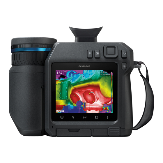
Camera overview 9.1 View from the rear 1. Focus ring. 2. Speaker. 3. Programmable button. 4. Image archive button. 5. Navigation pad with center push. 6. Back button. 7. On/off button. 8. Hand strap. 9. Multi-touch LCD screen. 10. Light sensor. 11. -
Page 27: View From The Front
Camera overview 9.2 View from the front 1. Autofocus button. 2. Save button. 3. Viewfinder. 4. Knob to change the dioptric correction for the viewfinder. 5. Attachment point for the neck strap. 6. Laser receiver. 7. Laser transmitter. 8. Camera lamp (left and right sides). 9. -
Page 28: View From The Bottom
5. Battery. 9.4 Lenses The FLIR GF77 has the following lens options: 25° LR (7.0–8.5 μm), 25° HR (9.5–12 μm), 6° LR (7.0–8.5 μm), and 6° LR (9.5–12 μm). The waveband is printed on the front of the lens and on a colored field inside the lens; red for LR and green for HR. -
Page 29: Laser Transmitter And Receiver
Camera overview Note • The laser is enabled by a setting. Select (Settings) > Device settings > Lamp & la- ser > Enable lamp & laser. • The symbol is displayed on the screen when the laser is on. • The camera can be configured to automatically measure the distance when an image is saved. -
Page 30: Laser Warning Label
Camera overview 9.5.4 Laser warning label A laser warning label with the following information is attached to the camera: 9.5.5 Laser rules and regulations Wavelength: 650 nm. Maximum output power: 1 mW. This product complies with 21 CFR 1040.10 and 1040.11 except for deviations pursuant to Laser Notice No. -
Page 31: Menu System
Camera overview 9.7.2 Menu system To display the menu system, push the navigation pad or tap the menu system button 1. Recording mode button. 2. Measurement parameters button. 3. Image mode button. 4. Measurement button. 5. Color button. 6. Settings button. 7. -
Page 32: Status Icons And Indicators
Camera overview Note • Before you can turn on the camera lamp, you need to enable the lamp. Select (Settings) > Device settings > Lamp & laser > Enable lamp & laser or Enable lamp & laser + Use lamp as flash. •... -
Page 33: Image Overlay
Camera overview 9.7.6 Image overlay The camera saves image information such as date, time, and items related to tempera- ture measurements to the image file. This image information can be viewed in the image archive. You can also choose to display selected image information items, and also lens information, as an overlay on the image. - Page 34 Camera overview • To navigate in menus, submenus, and dialog boxes, and to change values in dialog boxes, push the navigation pad up/down or left/right. • To confirm changes and settings in menus and dialog boxes, push the center of the navigation pad.
-
Page 35: Detecting A Gas Leak
Detecting a gas leak 10.1 General Full gas detection functionality, including High Sensitivity Mode (HSM) (see section 10.4 Enhancing the image using High Sensitivity Mode (HSM), page 28), is available when the camera is set to Gas detection mode. You can use the camera to also detect gas in Temperature measurements mode. With this setting, however, High Sensitivity Mode is not available. -
Page 36: Enhancing The Image Using High Sensitivity Mode (Hsm)
Detecting a gas leak Note For large lenses that cover the laser transmitter and receiver, the laser functional- ity is disabled. This means that continuous autofocus is not available. 10.4 Enhancing the image using High Sensitivity Mode (HSM) 10.4.1 General High Sensitivity Mode (HSM) is an adjustment method specifically designed for gas de- tection applications. -
Page 37: Changing The Color Palettes
Detecting a gas leak 10.6 Changing the color palettes You can change the color palette that the camera uses to display different temperatures. A different palette can make it easier to see a gas cloud. For more information, see sec- tion 13 Color palettes, page 38. -
Page 38: Measuring Temperatures
Measuring temperatures 11.1 General To measure a temperature, you can use one or more measurement tools, e.g., a spot- meter or a box. For more information, see section 18 Working with measurement tools, page 58. By using color alarms (isotherms), temperature anomalies can easily be discovered in an infrared image. -
Page 39: Autofocus
Measuring temperatures 11.3.2 Autofocus You can autofocus the infrared camera by pushing the Autofocus button. For more infor- mation, see section 21.5 Autofocusing the infrared camera, page 82. WARNING When the camera is set to autofocusing with the laser method (Settings > Device settings > Focus > Au- to focus >Laser), do not point the camera at the face of a person when you use the autofocus function. -
Page 40: Procedure
Measuring temperatures For accurate temperature measurements, you must change the Camera temperature range setting to suit the expected temperature of the object you are inspecting. Note For more information, see section 30 About calibration, page 118. 11.5.2 Procedure Follow this procedure: 1. -
Page 41: Performing An Nuc Manually
Measuring temperatures other optical and geometrical disturbances . For more information, see section 30 About calibration, page 118. An NUC is performed automatically, for example at start-up, when changing a measure- ment range, or when the environment temperature changes. You can also perform an NUC manually. This is useful when you have to perform a critical measurement with as little image disturbance as possible. -
Page 42: Infrared Image Adjustment
Infrared image adjustment 12.1 General An infrared image can be adjusted automatically or manually. In automatic mode, the camera continuously adjusts the level and span for the best im- age presentation. The colors are distributed based on the thermal content of the image (histogram color distribution). -
Page 43: Manual Adjustment By Touching The Screen
Infrared image adjustment 12.3 Manual adjustment by touching the screen 12.3.1 General The touch functionality for manual image adjustments is enabled/disabled by a setting. Select (Settings) > Device settings > User interface options > Manual adjustment us- ing touch > On/Off. When manual image adjustment mode is active, an adjustment wheel is displayed to the right of the temperature scale. -
Page 44: Locking The Touch Screen
Infrared image adjustment 12.3.4 Locking the touch screen When you have adjusted the image to levels that allow you to study your area of interest, you can lock the touch screen to prevent further unintentional adjustments. To lock the screen, touch the icon to the left of the temperature scale. - Page 45 Infrared image adjustment 1. In live mode, touch the soft button to enter manual image adjustment mode. 2. To simultaneously change the temperature scale minimum and maximum limits, push the navigation pad up/down. 3. To change the minimum limit or the maximum limit, do the following: •...
-
Page 46: Color Palettes
Color palettes 13.1 General You can change the color palette that the camera uses to display different temperatures. A different palette can make it easier to see a gas cloud and to analyze an image. This table explains the different types of color palettes. Iron Arctic Rainbow... -
Page 47: Changing The Color Palettes
Color palettes White hot Black hot Lava 13.2 Changing the color palettes 1. Push the navigation pad to display the menu system. 2. Select (Color) and push the navigation pad. This displays a submenu. 3. Use the navigation pad to select a different palette. 4. -
Page 48: Image Modes
• For the Thermal MSX, Thermal, and Picture in picture image modes, all thermal and visual information is stored when an image is saved. This means that you can edit the image later, in the image archive or in a FLIR Thermography software, and select any of the image modes. -
Page 49: Selecting An Image Mode
Image modes Image mode Image Thermal Thermal MSX Picture in picture Digital camera 14.3 Selecting an image mode 1. Push the navigation pad to display the menu system. 2. Select (Image mode) and push the navigation pad. This displays a submenu. #T810411;... - Page 50 Image modes 3. Use the navigation pad to select one of the following: • (Thermal MSX). • (Thermal). • (HSM). • (Picture in picture). • (Digital camera). Note • If the *.csq video format is selected (Settings > Save options & storage > Video compression) and the recording mode Video is selected, it will only be possible to select the image mode Thermal.
-
Page 51: Recording Modes
◦ Radiometric storage (*csq): A *.csq file supports full radiometry but is only sup- ported by FLIR Systems software. The file does not include any visual image infor- mation. With this setting, it is not possible to record video in HSM mode. Also, only the image mode Thermal is supported. -
Page 52: Time-Lapse
Recording modes 15.4 Time-lapse 15.4.1 General You can program the camera to save images periodically (time-lapse). 15.4.2 Procedure 1. Push the navigation pad to display the menu system. 2. Select (Recording mode) and push the navigation pad. This displays a submenu. 3. -
Page 53: Working With Images
Working with images 16.1 Saving an image Note This procedure assumes that you have set up the camera for single shot record- ing. Select (Recording mode) > (Single shot). 1. To save an image, push the Save button. Note Depending on the settings in (Settings) >... -
Page 54: Procedure
Working with images 16.3.2 Procedure 1. In Preview mode, push the navigation pad. This displays a context menu. • Select (Cancel) to exit edit mode. • Select (Measurement parameters) to change the global parameters. • Select (Image mode) to change the image mode. •... -
Page 55: Adding A Text Comment Table
Working with images 16.4.2.2 Procedure Follow this procedure: 1. Open the image in the image archive. 2. Push the navigation pad to display the top toolbar. 3. On the top toolbar, select the icon and push the navigation pad. 4. On the right toolbar, select the icon and push the navigation pad. - Page 56 16.4.3.3.2 Manually creating a table template 16.4.3.3.2.1 General A text comment file (*.tcf) is an annotation format that is proprietary to FLIR Systems. It defines a table structure that can be used to add text table annotations to FLIR images.
-
Page 57: Adding A Voice Annotation
A voice annotation is an audio recording that is saved to the infrared image file. The re- cording can be played back in the camera, and in image analysis and reporting software from FLIR Systems. The voice annotation is recorded using the built-in microphone. You can also use a Blue- tooth-enabled headset. -
Page 58: Adding A Sketch
Working with images 16.4.4.2 Procedure Follow this procedure: 1. Open the image in the image archive. 2. Push the navigation pad to display the top toolbar. 3. On the top toolbar, select the icon and push the navigation pad. 4. On the right toolbar, select the icon and push the navigation pad. - Page 59 Working with images 16.4.5.2 Procedure Follow this procedure: 1. Open the image in the image archive. 2. Push the navigation pad to display the top toolbar. 3. On the top toolbar, select the icon and push the navigation pad. 4. On the right toolbar, select the icon and push the navigation pad.
-
Page 60: Gallery - Video And Image Archive
Gallery — video and image archive 17.1 General When you save a video clip or an image, the camera stores the video/image file in the im- age archive on the memory card. You can open and play saved video clips in the image archive. -
Page 61: Opening A Saved Image
Gallery — video and image archive 4. To play the video clip, do the following: 4.1. Push the navigation pad to display the top toolbar. 4.2. On the top toolbar, select the icon and push the navigation pad. 4.3. To play or pause the video clip, push the navigation pad. 5. -
Page 62: Related Topics
Gallery — video and image archive 8. Push the navigation pad. This displays a context menu. • Select (Cancel) to exit edit mode. • Select (Measurement parameters) to change the global parameters. • Select (Image mode) to change the image mode. •... -
Page 63: Renaming A Folder
Gallery — video and image archive 5. The new folder automatically becomes the active folder and appears at the top of the Gallery. Note You can also create a new folder via the soft button 17.7 Renaming a folder You can change the name of the folders in the archive. The active folder cannot be renamed. -
Page 64: Deleting A Folder
Gallery — video and image archive 4. Use the navigation pad to select the image and video items you want to move. You can also select the items by touching the screen. Selected items are marked with a tick. 5. On the right toolbar, select the icon and push the navigation pad. -
Page 65: Deleting Multiple Files
Gallery — video and image archive 17.12 Deleting multiple files 17.12.1 General You can delete multiple video and image files from the image archive. 17.12.2 Procedure 1. Push the image archive button . This displays the Gallery . 2. Select a folder and push the navigation pad. 3. -
Page 66: Working With Measurement Tools
Working with measurement tools 18.1 General To measure a temperature, you can use one or more measurement tools, e.g., a spot- meter or a box. Note The temperature measurement functionality is enabled by a setting. Select (Settings) > Application options > Gas camera mode > Temperature measurements. 18.2 Adding/removing measurement tools Follow this procedure: 1. -
Page 67: Procedure
Working with measurement tools 18.3.2 Procedure Follow this procedure: 1. Push the navigation pad to display the menu system. 2. Select (Measurement) and push the navigation pad. This displays a submenu. 3. Use the navigation pad to select (User preset 1) or (User preset 2). -
Page 68: Moving And Resizing A Box Or Circle Tool
Working with measurement tools 3. To move the spot, do the following: 3.1. Select (Move spot) and push the navigation pad. 3.2. Push the navigation pad up/down and left/right to move the spot. 4. To center the spot, select Center spot and push the navigation pad. 5. -
Page 69: Recommended Values
Working with measurement tools • Atmospheric temperature, i.e., the temperature of the air between the camera and the object of interest. • Relative humidity, i.e., the relative humidity of the air between the camera and the ob- ject of interest. •... - Page 70 Working with measurement tools 3. Use the navigation pad to select one or more of the global measurement parameters: • (External IR window compensation). • (Object distance). • (Atmospheric temperature). • (Relative humidity). • (Reflected temperature). • (Emissivity). 4. Push the navigation pad to display a dialog box. 5.
-
Page 71: Displaying Values In The Result Table
Working with measurement tools Note When you select another measurement tool, the local parameters are reset. If you wish to keep the local parameter settings, use the user preset feature, see section 18.3 Editing user presets, page 58. 18.6 Displaying values in the result table 18.6.1 General For the box and circle tools, you can set the camera to display the maximum, minimum, average, and area values in the result table. -
Page 72: Creating And Setting Up A Difference Calculation
Working with measurement tools 8. Select (Done) and push the navigation pad. 18.7 Creating and setting up a difference calculation 18.7.1 General A difference calculation gives the difference between the values of two known measure- ment results. 18.7.2 Procedure Note •... -
Page 73: Procedure
Working with measurement tools You can also set an audible alarm (there will be a “beep” when the alarm is triggered). 18.8.4 Procedure There are different procedures for setting up an alarm for a spot, for a box or circle, and for a difference calculation. - Page 74 Working with measurement tools 4. In the dialog box, you can define the settings for the alarm. • Alarm condition: The condition that triggers the alarm. Applicable values are Above, Below, or Off. • Select measurement: Applicable settings are the values you have previously de- fined (Max, Min, and/or Avg).
-
Page 75: Working With Color Alarms And Isotherms
Working with color alarms and isotherms 19.1 General Color alarms and isotherms are functions applicable to temperature measurements. The temperature measurement functionality is enabled by a setting. Select (Set- tings) > Application options > Gas camera mode > Temperature measurements. 19.2 Color alarms 19.2.1 General By using color alarms (isotherms), anomalies can easily be discovered in an infrared im-... -
Page 76: Setting Up Above, Below, And Interval Alarms
Working with color alarms and isotherms Image Color alarm Interval alarm Condensation alarm Insulation alarm 19.2.3 Setting up above, below, and interval alarms Follow this procedure: 1. Push the navigation pad to display the menu system. 2. Select (Color) and push the navigation pad. This displays a submenu. 3. -
Page 77: Building Isotherms
Working with color alarms and isotherms 19.2.4 Building isotherms Note The Condensation and Insulation alarms are not supported by all camera models. 19.2.4.1 About the Condensation alarm To detect areas with potential moisture problems, you can use the Condensation alarm. You can set the relative humidity above which the isotherm will colorize the image. - Page 78 Working with color alarms and isotherms 4. Push the navigation pad. This displays a dialog box where you can define the settings for the alarm. For the Condensation alarm, the following parameters can be set: • Atmospheric temperature: The current atmospheric temperature. •...
-
Page 79: Inspection Route
1. Prepare the inspection route file, using one of the following methods: • FLIR thermography software that has inspection route support. • Your own solution. The FLIR Thermal SDK can be used to build your own export/ import software or to interface your existing asset management system. -
Page 80: Drop-Down Menu
Inspection Route ◦ Displays an image icon if there is an image saved for the inspection point. ◦ Displays the status of the inspection point. • Next arrow Tap to go to the next inspection point. • Document icon This icon is displayed if there is a description and/or comment available for the inspec- tion point. -
Page 81: Performing An Inspection
Inspection Route Figure 20.1 Figure 20.1 shows an example of the inspection list: • The first inspection route is completed and locked, which is indicated by the check mark to the right. • The second inspection route has started. It includes a total of 91 inspection points, and one of them has been inspected. -
Page 82: Capturing Inspection Data
Inspection Route 4. Activate the Inspection Route function by selecting (Settings) > Save options & storage > Inspection route > On. 5. The camera is now ready. 20.3.2 Capturing inspection data Once the camera is prepared, the inspection can start. Note You can turn off the camera in the middle of an inspection. -
Page 83: Editing Inspection Point Data
Inspection Route 8. When you have completed the inspection, transfer the inspection results to a com- puter for post-processing. For more information, see section 20.3.9 Transferring in- spection results. 20.3.3 Editing inspection point data You can edit the data for the inspection point displayed by the current point indicator. To go to another inspection point, use the back or next arrow or select the inspection point from the inspection list, see section 20.3.7 Inspection list. -
Page 84: Inspection List
Inspection Route 20.3.7 Inspection list In the inspection list, you can see the progress of the inspection routes and review the in- spection point results. To see the progress and review the results, do the following: 1. Tap the current point indicator. This displays a drop-down menu. 2. -
Page 85: Creating An Inspection Route
The inspection route file can be created using one of the following methods: • FLIR thermography software that has inspection route support. • Your own solution. The FLIR Thermal SDK can be used to build your own export/im- port software or to interface your existing asset management system. -
Page 86: Manually Editing An Xml File
Inspection Route 9. When the inspection route is completed, make sure to copy the XML file on the mem- ory card to a computer for future use. When you start an inspection in the camera, the inspection data will be written to the XML file on the memory card. 20.5.2 Manually editing an XML file An example or empty XML file can be created on the memory card in the camera. -
Page 87: Handling The Camera
Handling the camera 21.1 Charging the battery 21.1.1 General • Before starting the camera for the first time, charge the battery for 3 hours using the stand-alone battery charger. • Select a mains socket that is near the equipment and easily accessible. 21.1.2 Using the stand-alone battery charger to charge the battery 21.1.2.1 Stand-alone battery charger LED indicator Type of signal... -
Page 88: Charging The Battery Using A Usb Cable Connected To A Computer
Handling the camera 6. It is good practice to disconnect the USB battery charger from the mains socket when the battery is fully charged. Note When closing the cover for the connector compartment, firmly press along the edges of the cover to make sure that it closes tightly. 21.1.4 Charging the battery using a USB cable connected to a computer Follow this procedure: 1. -
Page 89: Turning On And Turning Off The Camera
Handling the camera 2. Push the two release buttons and remove the battery from the camera. 21.3 Turning on and turning off the camera • To turn on the camera, push the on/off button • To turn off the camera, push and hold the on/off button for more than 0.5 second. -
Page 90: Autofocusing The Infrared Camera
Handling the camera • For far focus, rotate the focus ring clockwise (with the LCD screen facing toward you). • For near focus, rotate the focus ring counter-clockwise (with the LCD screen facing to- ward you). Note • Do not touch the lens surface when you adjust the infrared camera focus manually. If this happens, clean the lens according to the instructions in 22.2 Infrared lens, page •... -
Page 91: Continuous Autofocus
Handling the camera Note You can also assign the autofocus function to one of the programmable buttons. For more information, see section 21.15 Assigning functions to the programmable but- tons, page 90. 21.6 Continuous autofocus 21.6.1 General The infrared camera can be set up to perform continuous autofocusing. When the continuous autofocus function is enabled, the camera bases the focus adjust- ments on continuous laser distance measurements. -
Page 92: A Note About Ergonomics
Handling the camera To digitally zoom an image, do the following: • Zoom in: Touch the screen with two fingers and spread the fingers apart. • Zoom out: Touch the screen with two fingers and pinch the fingers together. 21.8 A note about ergonomics 21.8.1 General To prevent strain-related injuries, it is important that you hold the camera ergonomically correctly. -
Page 93: Figure
Handling the camera 21.8.2 Figure #T810411; r. AC/70277/70566; en-US... -
Page 94: Adjusting The Viewfinder's Dioptric Correction (Sharpness)
Handling the camera 21.9 Adjusting the viewfinder’s dioptric correction (sharpness) CAUTION Make sure that the beams from the intensive energy sources do not go into the viewfinder. The beams can cause damage to the camera. This includes the devices that emit laser radiation, or the sun. To adjust the viewfinder’s dioptric correction, look through the viewfinder and rotate the adjustment knob clockwise or counter-clockwise for the best sharpness. -
Page 95: Adjusting The Angle Of The Lens
Handling the camera 21.10 Adjusting the angle of the lens To adjust the angle, tilt the lens up or down. 21.11 Operating the laser distance meter 21.11.1 General The laser distance meter consists of a laser transmitter and a laser receiver. The laser distance meter determines the distance to a target by measuring the time it takes for a la- ser pulse to reach the target and return to the laser receiver. -
Page 96: Procedure
Handling the camera Note • The laser is enabled by a setting. Select (Settings) > Device settings > Lamp & la- ser > Enable lamp & laser. • The symbol is displayed on the screen when the laser is on. •... -
Page 97: Connecting External Devices And Storage Media
Handling the camera 2. Set the camera to measure and display the area of the box or circle, see section 18.6 Displaying values in the result table, page 63. 3. Make sure that the box or circle tool is in the center of the image, see section 18.4 Moving and resizing a measurement tool, page 59. -
Page 98: Moving Files To A Computer
Note Moving a file using a drag-and-drop operation does not delete the file in the camera. • Import the images into a FLIR Thermography software. Note When closing the cover for the connector compartment, firmly press along the edges of the cover to make sure that it closes tightly. - Page 99 Handling the camera You can assign different functions to the programmable buttons. You can, for example, use a programmable button to easily switch between two settings you use often. You can also choose to define two different setups for saving and previewing: the usual setup for the Save button (which is defined by the Save options and storage settings, see section 23.4 Save options &...
-
Page 100: Procedure
Handling the camera • Save + Prompt for voice annotation: Save an image and display the voice annotation tool. • Save + Prompt for sketch: Save an image and display the sketch annotation tool. • Save + Select annotation from menu: Save an image and display the annotation tool menu. -
Page 101: Procedure
21.18 Changing the camera lenses Note Before a new lens can be used with the camera, the lens–camera combination must be calibrated. This is a process that has to be performed by a FLIR service department. Note Do not touch the lens surface when you change lenses. If this happens, clean the lens according to the instructions in 22.2 Infrared lens, page 99. - Page 102 Handling the camera 2. Carefully pull out the lens. 3. The infrared detector is now fully exposed. Do not touch this surface. If you see dust on the detector, follow the instructions in 22.3 Infrared detector, page 100. #T810411; r. AC/70277/70566; en-US...
- Page 103 Handling the camera 4. Make sure that the inner ring of the camera lens is fully in its open position. • Correct: The tooth (1) is in its end position at the black stop pin (2). • Wrong: You must rotate the inner ring until the tooth (1) reaches the black stop pin (2).
- Page 104 Handling the camera 6. Rotate the inner ring of the lens 30° clockwise. The lens makes a click when it locks in place. 7. Make sure that the two index marks are aligned, indicating that the lens is locked in place.
-
Page 105: Neck Strap
Handling the camera 21.19 Neck strap To attach the neck strap to the camera, use the two attachment points indicated in the figure. 21.20 Hand strap To replace the hand strap, follow this procedure: 1. Remove the battery. 2. Open the hook-and-loop fastener and remove the hand strap from the upper attach- ment point. - Page 106 Handling the camera 4. Remove the hand strap from the bracket at the base of the camera. 5. Put the new hand strap into the bracket at the base of the camera. 6. Push the bracket into the camera. Make sure that the two holes in the hand strap are aligned with the holes in the bracket.
-
Page 107: Cleaning The Camera
Cleaning the camera 22.1 Camera housing, cables, and other items 22.1.1 Liquids Use one of these liquids: • Warm water • A weak detergent solution 22.1.2 Equipment A soft cloth 22.1.3 Procedure Follow this procedure: 1. Soak the cloth in the liquid. 2. -
Page 108: Infrared Detector
Cleaning the camera 22.3 Infrared detector 22.3.1 General Even small amounts of dust on the infrared detector can result in major blemishes in the image. To remove any dust from the detector, follow the procedure below. Note • This section only applies to cameras where removing the lens exposes the infrared detector. -
Page 109: Camera Settings
Camera settings You can change a variety of settings in the camera. You do this on the Settings menu. The available settings depend on the Gas camera mode setting (see section 23.1 Appli- cation options, page 101) and on the lens model. The Settings menu includes the following: •... -
Page 110: Device Settings
◦ Radiometric storage (*.csq): A CSQ file supports full radiometry but is only sup- ported by FLIR Systems software. The file does not include any visual image infor- mation. With this setting, it is not possible to record video in HSM mode. Also, only the image mode Thermal is supported when recording video. - Page 111 Camera settings Note You can also enable/disable screen rotation on the swipe-down menu. For more information, see section 9.7.5 Swipe-down menu, page 24. ◦ Image overlay information: This setting specifies what image information, and also lens information, the camera will display as an overlay on the image. For more in- formation, see section 9.7.6 Image overlay, page 25.
- Page 112 Camera settings ◦ Reset device settings to factory default...: This setting will affect all camera settings, including regional settings. Saved videos/images will not be affected. The camera will be restarted and you will be prompted to set the regional settings. ◦...
-
Page 113: Configuring Wi-Fi
Configuring Wi-Fi 24.1 General Depending on your camera configuration, you can connect the camera to a wireless local area network (WLAN) using Wi-Fi, or let the camera provide Wi-Fi access to other devices. You can connect the camera in two different ways: •... -
Page 114: Pairing Bluetooth Devices
7. When a Bluetooth device is found, select the device to add it, and begin the pairing procedure. The device is then ready to be used. Note • Only METERLiNK devices (FLIR meters) and Bluetooth-enabled headsets will appear in the list of available devices. • You can add several devices. -
Page 115: Fetching Data From External Flir Meters
The live value is displayed with a dotted outline. If the screen display for values is full, it is still possible to add more values from the FLIR meter. Added values are then indicated by a box with a number that counts up each time a new value is added. -
Page 116: Typical Moisture Measurement And Documentation Procedure
Fetching data from external FLIR meters 4. On the FLIR meter, choose the quantity that you want to use (voltage, current, resist- ance, etc.). Refer to the user documentation for the meter for information on how to do this. Results from the meter will now automatically be displayed in the result table in the top left corner of the infrared camera screen. -
Page 117: About Video And Image Files
The image *.jpg file is fully radiometric and saved lossless, which enables full post-proc- essing in image analysis and reporting software from FLIR Systems. There is also a reg- ular *.jpg component (lossy) for convenient viewing in non-FLIR Systems software (e.g., Microsoft Explorer). -
Page 118: Ultramax
UltraMax image. Some FLIR Thermography software has the ability to process UltraMax images. Other FLIR software will treat the image as a regular image. -
Page 119: Mechanical Drawings
Mechanical drawings [See next page] #T810411; r. AC/70277/70566; en-US... -
Page 124: Ce Declaration Of Conformity
CE Declaration of conformity [See next page] #T810411; r. AC/70277/70566; en-US... -
Page 126: About Calibration
30.3 Camera calibration at FLIR Systems Without calibration, an infrared camera would not be able to measure either radiance or temperature. At FLIR Systems, the calibration of uncooled microbolometer cameras with a measurement capability is carried out during both production and service. Cooled cam- eras with photon detectors are often calibrated by the user with special software. -
Page 127: The Differences Between A Calibration Performed By A User And That Performed Directly At Flir Systems
The calibration information, no matter if the calibration is done by FLIR Systems or the user, is stored in calibration curves, which are expressed by mathematical functions. As... -
Page 128: Non-Uniformity Correction
About calibration Calibration is also a prerequisite for adjustment, which is the set of operations carried out on a measuring system such that the system provides prescribed indications corre- sponding to given values of quantities to be measured, typically obtained from measure- ment standards. -
Page 129: About Flir Systems
• Extech Instruments (2007) Figure 31.1 Patent documents from the early 1960s FLIR Systems has three manufacturing plants in the United States (Portland, OR, Boston, MA, Santa Barbara, CA) and one in Sweden (Stockholm). Since 2007 there is also a manufacturing plant in Tallinn, Estonia. -
Page 130: More Than Just An Infrared Camera
31.1 More than just an infrared camera At FLIR Systems we recognize that our job is to go beyond just producing the best infra- red camera systems. We are committed to enabling all users of our infrared camera sys- tems to work more productively by providing them with the most powerful camera–... -
Page 131: Supporting Our Customers
31.3 Supporting our customers FLIR Systems operates a worldwide service network to keep your camera running at all times. If you discover a problem with your camera, local service centers have all the equipment and expertise to solve it within the shortest possible time. - Page 132 Disclaimer Specifications subject to change without further notice. Models and accessories subject to regional market considerations. License procedures may apply. Products described herein may be subject to US Export Regulations. Please refer to exportquestions@flir.com with any questions. Publ. No.: T810411...
Need help?
Do you have a question about the GF7 Series and is the answer not in the manual?
Questions and answers