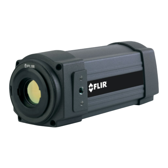
FLIR A3 series User Manual
Hide thumbs
Also See for A3 series:
- Installation manual (108 pages) ,
- Getting started manual (74 pages) ,
- User manual (104 pages)
Table of Contents
Advertisement
Quick Links
Advertisement
Table of Contents

Related Manuals for FLIR A3 series


Summary of Contents for FLIR A3 series
- Page 1 User’s manual FLIR A3xx/A3xx sc series...
- Page 3 User’s manual FLIR A3xx/A3xx sc series #T559498; r.22370/22370; en-US...
-
Page 5: Table Of Contents
Procedure ..............15 Removing an additional infrared lens........... 15 8.2.1 Procedure ..............15 Connectors, controls, and indicators ..........16 FLIR A3xx series ..............16 Explanation ................16 FLIR A3xx sc series..............16 Explanation ................16 Example system overviews............... 18 10.1 FLIR A3xx series .............. - Page 6 13.8 FLIR A315................45 13.9 FLIR A315 (9 Hz) ..............48 13.10 FLIR A320 Tempscreen............51 13.11 FLIR A320 Tempscreen (9 Hz) ........... 55 13.12 FLIR A325sc................59 Mechanical drawings ............... 62 Pin configurations ................71 15.1 Pin configuration for I/O connector ..........71 15.2...
- Page 7 Table of contents 19.4 Distance ................83 19.5 Relative humidity ..............83 19.6 Other parameters..............83 History of infrared technology............85 Theory of thermography..............88 21.1 Introduction ................88 21.2 The electromagnetic spectrum........... 88 21.3 Blackbody radiation..............88 21.3.1 Planck’s law ..............89 21.3.2 Wien’s displacement law..........
-
Page 9: Legal Disclaimer
Products which are not manufactured by FLIR Systems but included in systems deliv- ered by FLIR Systems to the original purchaser, carry the warranty, if any, of the particu- lar supplier only. FLIR Systems has no responsibility whatsoever for such products. -
Page 10: Quality Assurance
1.8 EULA Terms • You have acquired a device (“INFRARED CAMERA”) that includes software licensed by FLIR Systems AB from Microsoft Licensing, GP or its affiliates (“MS”). Those in- stalled software products of MS origin, as well as associated media, printed materials, and “online”... - Page 11 Legal disclaimer • NO WARRANTIES FOR THE SOFTWARE. THE SOFTWARE is provided “AS IS” and with all faults. THE ENTIRE RISK AS TO SATISFACTORY QUALITY, PER- FORMANCE, ACCURACY, AND EFFORT (INCLUDING LACK OF NEGLIGENCE) IS WITH YOU. ALSO, THERE IS NO WARRANTY AGAINST INTERFERENCE WITH YOUR ENJOYMENT OF THE SOFTWARE OR AGAINST INFRINGEMENT.
-
Page 12: Safety Information
Safety information WARNING Make sure that you read all applicable MSDS (Material Safety Data Sheets) and warning labels on con- tainers before you use a liquid. The liquids can be dangerous. Injury to persons can occur. CAUTION Do not point the infrared camera (with or without the lens cover) at strong energy sources, for example, devices that cause laser radiation, or the sun. -
Page 13: Notice To User
3.2 Calibration FLIR Systems recommends that you verify your calibration yearly. You can verify the cali- bration yourself or with the help of a FLIR Systems Partner. If preferred, FLIR Systems of- fers a calibration, adjustment, and general maintenance service. -
Page 14: Customer Help
Customer help 4.1 General For customer help, visit: http://support.flir.com 4.2 Submitting a question To submit a question to the customer help team, you must be a registered user. It only takes a few minutes to register online. If you only want to search the knowledgebase for existing questions and answers, you do not need to be a registered user. -
Page 15: Downloads
• The communication protocol, or method, between the camera and your device (for ex- ample, HDMI, Ethernet, USB, or FireWire) • Device type (PC/Mac/iPhone/iPad/Android device, etc.) • Version of any programs from FLIR Systems • Full name, publication number, and revision number of the manual 4.3 Downloads On the customer help site you can also download the following: •... -
Page 16: List Of Accessories And Services
T197896 High temp option +300°C to 2000°C (+572°F to 3632°F) for FLIR A6xxsc and T6xx T197000 High temp. option +1200°C/+2192°F for FLIR T/ B2xx to T/B4xx and A3xx, A3xxf, A3xxpt, A3xxsc series T197411 IR lens, 4 mm (90°) with case and mounting sup-... - Page 17 List of accessories and services Part number Product name ITC-ADV-3029 ITC Advanced General Thermography Course- group of 10 pers. ITC-ADV-3061 ITC Advanced Thermal applications course - at- tendance 1 pers. (3 days) ITC-ADV-3069 ITC Advanced Thermal applications course - group up to 10 pers. (3 days) ITC-ADV-3041 ITC Advanced Thermal measurements (R&D) - at- tendance 1 pers.
- Page 18 USB cable Std A <-> Mini-B 908929 Video cable, 3.0 m/9.8 ft. NOTE FLIR Systems reserves the right to discontinue models, parts or accessories, and other items, or to change specifications at any time without prior notice. #T559498; r.22370/22370; en-US...
-
Page 19: Installation
• FLIR IR Camera Player: A PC-based remote control and video player for IR cameras from FLIR Systems. • A link to a web installation of FLIR AXXX Control & Image Interfaces: An installation that includes Interface Control Documents (ICDs), user documentation and C-code examples. -
Page 20: Installation
CD-ROM. We recommend that you read this file before you install the programs. NOTE • If you experience problems during the installation, visit our Customer Help at http://support.flir.com. • You must be an Administrator or a user with Administrative Rights to install the programs. -
Page 21: Mechanical Installation
7.4 Further information For further information regarding installation recommendations and environmental enclo- sures, contact FLIR Systems. 7.5 Cable strain relief In installations were the camera is subject to vibrations or shocks the power cord may need an external strain relief arrangement to avoid power port failure. - Page 22 Mechanical installation Example 2, cable strain relief with cable clamps. #T559498; r.22370/22370; en-US...
-
Page 23: Mounting And Removing Lenses
Mounting and removing lenses 8.1 Mounting an additional infrared lens NOTE Do not touch the lens surface when you mount an infrared lens. If this happens, clean the lens accord- ing to the instructions in section 16.2 Infrared lens, page 72. 8.1.1 Procedure Follow this procedure to mount an additional infrared lens: 1. -
Page 24: Connectors, Controls, And Indicators
Use an unbent paper clip or a similar tool to press the reset button through the small hole on the back of the camera for 5 seconds, then release the button. 9.3 FLIR A3xx sc series 9.4 Explanation 1. Network cable with an RJ45 connector for Ethernet connectivity and PoE (dependent on the camera model). - Page 25 Connectors, controls, and indicators 2. Power cable for 12–24 V DC power in. NOTE The power connector on the camera is polarity protected. 3. Digital I/O ports, opto-isolated (six-pole screw terminal). A.Power indicator. NOTE The LEDs indicate the following: B.Hardware reset button (for a factory default reset). Use an unbent paper clip or a similar tool to press the reset button through the small hole on the back of the camera for 5 seconds, then release the button.
-
Page 26: Example System Overviews
Example system overviews 10.1 FLIR A3xx series 10.1.1 Figure 10.1.2 Explanation 1. Computer. 2. CAT-6 Ethernet cable with RJ45 connectors. 3. Industrial Ethernet switches with fiber-optic ports. 4. Fiber-optic cable. 5. FLIR A3xx cameras. 6. Industrial process to be monitored, e.g., items on a conveyor belt. -
Page 27: Figure
Example system overviews 10.1.3 Figure 10.1.4 Explanation 1. Computer. 2. CAT-6 Ethernet cable with RJ45 connectors. 3. Industrial Ethernet switch. 4. FLIR A3xx cameras. 5. Industrial process to be monitored, e.g., a gasifier. #T559498; r.22370/22370; en-US... -
Page 28: Figure
3. Industrial Ethernet switches with fiber optic ports. 4. Fiber-optic cable. 5. Wireless access points. 6. CAT-6 Ethernet cable with RJ45 connectors—powering the camera using PoE (de- pendent on the camera model). 7. Industrial Ethernet switch. 8. FLIR A3xx cameras. #T559498; r.22370/22370; en-US... -
Page 29: Flir A3Xx Sc Series
Example system overviews 10.2 FLIR A3xx sc series 10.2.1 Figure 10.2.2 Explanation 1. Computer. 2. CAT-6 Ethernet cable with RJ45 connectors. 3. Laboratory set-up with a FLIR A3xx sc camera. #T559498; r.22370/22370; en-US... -
Page 30: Temperature Screening
NOTE • You can change the temperature by 2°C (3.6°F) (described below) using the Screening tab in FLIR IR Monitor (included on the ThermoVision System Tools & Utilities 1.5.1 HF2 (1.5.1.16)). HF2 can be downloaded from http://support.flir.com. •... - Page 31 Temperature screening #T559498; r.22370/22370; en-US...
-
Page 32: Network Troubleshooting
Network troubleshooting Try one of the following if you experience network problems: • Reset the modem and unplug and replug the Ethernet cable at both ends. • Reboot the computer with the cables connected. • Swap your Ethernet cable with another cable that is either brand new or known to be in working condition. -
Page 33: Technical Data
FLIR A3xx/A3xx sc camera for field-of- view tables for all lens–camera combinations in this camera series. 13.2 Note about technical data FLIR Systems reserves the right to change specifications at any time without prior notice. Please check http://support.flir.com for latest changes. -
Page 34: Flir A300
Rev.: 22369 General description The FLIR A300 offers an affordable and accurate temperature measurement solution for anyone who needs to solve problems that do not call for the highest speed or reaction and who uses a PC. Due to its composite video output, it is also an excellent choice for thermal image automation applications, where you can utilize its unique properties such as looking through steam. - Page 35 Ethernet, type 100 Mbps Ethernet, standard IEEE 802.3 Ethernet, connector type RJ-45 Ethernet, communication TCP/IP socket-based FLIR proprietary Ethernet, video streaming MPEG-4, ISO/IEC 14496-1 MPEG-4 ASP@L5 Ethernet, image streaming 16-bit 320 × 240 pixels @ 3 Hz • Radiometric Ethernet, power Power over Ethernet, PoE IEEE 802.3af class 0.
- Page 36 • T197411; IR lens, 4 mm (90°) with case and mounting support for A3xx, A3xxsc • T197415; Close-up 1× (25 µm) incl. case and mounting support for A3xx, A3xxsc • T197000; High temp. option +1200°C/+2192°F for FLIR T/B2xx to T/B4xx and A3xx, A3xxf, A3xxpt, A3xxsc series •...
- Page 37 Technical data • T198583; FLIR Tools+ (license only) • DSW-10000; FLIR IR Camera Player • APP-10002; FLIR Tools Mobile (Android Application) • T198567; ThermoVision™ System Developers Kit Ver. 2.6 • T198566; ThermoVision™ LabVIEW® Digital Toolkit Ver. 3.3 #T559498; r.22370/22370; en-US...
-
Page 38: Flir A300 (9 Hz)
Rev.: 22369 General description The FLIR A300 (9 Hz) provides an affordable and accurate temperature measurement solution for any- one who needs to solve problems that do not call for the highest speed or reaction and who uses a PC. - Page 39 Ethernet, type 100 Mbps Ethernet, standard IEEE 802.3 Ethernet, connector type RJ-45 Ethernet, communication TCP/IP socket-based FLIR proprietary Ethernet, video streaming MPEG-4, ISO/IEC 14496-1 MPEG-4 ASP@L5 Ethernet, image streaming 16-bit 320 × 240 pixels @ 3 Hz • Radiometric Ethernet, power Power over Ethernet, PoE IEEE 802.3af class 0.
- Page 40 • T197411; IR lens, 4 mm (90°) with case and mounting support for A3xx, A3xxsc • T197415; Close-up 1× (25 µm) incl. case and mounting support for A3xx, A3xxsc • T197000; High temp. option +1200°C/+2192°F for FLIR T/B2xx to T/B4xx and A3xx, A3xxf, A3xxpt, A3xxsc series •...
- Page 41 Technical data • T198583; FLIR Tools+ (license only) • DSW-10000; FLIR IR Camera Player • APP-10002; FLIR Tools Mobile (Android Application) • T198567; ThermoVision™ System Developers Kit Ver. 2.6 • T198566; ThermoVision™ LabVIEW® Digital Toolkit Ver. 3.3 #T559498; r.22370/22370; en-US...
-
Page 42: Flir A305Sc
General description The FLIR A305sc is an excellent choice for those working in R&D but who do not need the highest frame rates or a resolution higher than 320 × 240 pixels. When using the camera in R&D, it is highly rec- ommended to use the FLIR ResearchIR software from FLIR Systems. - Page 43 Control and image Ethernet, type Gigabit Ethernet Ethernet, standard IEEE 802.3 Ethernet, connector type RJ-45 Ethernet, communication TCP/IP socket-based FLIR proprietary and GenI- Cam protocol Ethernet, image streaming 16-bit 320 × 240 pixels @ 9 Hz • Signal linear • Temperature linear •...
- Page 44 • T197411; IR lens, 4 mm (90°) with case and mounting support for A3xx, A3xxsc • T197415; Close-up 1× (25 µm) incl. case and mounting support for A3xx, A3xxsc • T197000; High temp. option +1200°C/+2192°F for FLIR T/B2xx to T/B4xx and A3xx, A3xxf, A3xxpt, A3xxsc series •...
-
Page 45: Flir A310
Ethernet hardware and software protocols. The FLIR A310 also has built in support to connect to industrial control equipment such as PLCs, and allows for sharing of analysis and alarm results and simple control using the Ethernet/IP and Modbus TCP field bus protocols. - Page 46 Ethernet, type 100 Mbps Ethernet, standard IEEE 802.3 Ethernet, connector type RJ-45 Ethernet, communication TCP/IP socket-based FLIR proprietary Ethernet, video streaming MPEG-4, ISO/IEC 14496-1 MPEG-4 ASP@L5 Ethernet, image streaming 16-bit 320 × 240 pixels @ 7-8 Hz • Radiometric #T559498; r.22370/22370; en-US...
- Page 47 In such cases, power the camera using the external power cable, or modify the camera according to Service bulletin SB14-006. For modification, please contact your local service department. See http://support.flir.com/service for contact details. Ethernet, protocols Ethernet/IP, Modbus TCP, TCP, UDP, SNTP, RTSP,...
- Page 48 • T197411; IR lens, 4 mm (90°) with case and mounting support for A3xx, A3xxsc • T197415; Close-up 1× (25 µm) incl. case and mounting support for A3xx, A3xxsc • T197000; High temp. option +1200°C/+2192°F for FLIR T/B2xx to T/B4xx and A3xx, A3xxf, A3xxpt, A3xxsc series •...
-
Page 49: Flir A310 (9 Hz)
Ethernet hardware and software protocols. The FLIR A310 also has built in support to connect to industrial control equipment such as PLCs, and allows for sharing of analysis and alarm results and simple control using the Ethernet/IP and Modbus TCP field bus protocols. - Page 50 Ethernet, type 100 Mbps Ethernet, standard IEEE 802.3 Ethernet, connector type RJ-45 Ethernet, communication TCP/IP socket-based FLIR proprietary Ethernet, video streaming MPEG-4, ISO/IEC 14496-1 MPEG-4 ASP@L5 Ethernet, image streaming 16-bit 320 × 240 pixels @ 4.5 Hz • Radiometric #T559498; r.22370/22370; en-US...
- Page 51 In such cases, power the camera using the external power cable, or modify the camera according to Service bulletin SB14-006. For modification, please contact your local service department. See http://support.flir.com/service for contact details. Ethernet, protocols Ethernet/IP, Modbus TCP, TCP, UDP, SNTP, RTSP,...
- Page 52 • T197411; IR lens, 4 mm (90°) with case and mounting support for A3xx, A3xxsc • T197415; Close-up 1× (25 µm) incl. case and mounting support for A3xx, A3xxsc • T197000; High temp. option +1200°C/+2192°F for FLIR T/B2xx to T/B4xx and A3xx, A3xxf, A3xxpt, A3xxsc series •...
-
Page 53: Flir A315
Rev.: 22369 General description The FLIR A315 has features and functions that make it the natural choice for anyone who uses PC soft- ware to solve problems and for whom 320 × 240 pixel resolution is sufficient. Among its main features are GigE Vision and GenICam compliance, which makes it plug-and-play when used with software packages such as IMAQ Vision and Halcon. - Page 54 Control and image Ethernet, type Gigabit Ethernet Ethernet, standard IEEE 802.3 Ethernet, connector type RJ-45 Ethernet, communication TCP/IP socket-based FLIR proprietary and GenI- Cam protocol Ethernet, image streaming 16-bit 320 × 240 pixels @ 60 Hz • Signal linear • Temperature linear •...
- Page 55 • T197411; IR lens, 4 mm (90°) with case and mounting support for A3xx, A3xxsc • T197415; Close-up 1× (25 µm) incl. case and mounting support for A3xx, A3xxsc • T197000; High temp. option +1200°C/+2192°F for FLIR T/B2xx to T/B4xx and A3xx, A3xxf, A3xxpt, A3xxsc series •...
-
Page 56: Flir A315 (9 Hz)
Rev.: 22369 General description The FLIR A315 (9 Hz) has features and functions that make it the natural choice for anyone who uses PC software to solve problems and for whom 320 × 240 pixel resolution is sufficient. Among its main features are GigE Vision and GenICam compliance, which makes it plug-and-play when used with soft- ware packages such as IMAQ Vision and Halcon. - Page 57 Control and image Ethernet, type Gigabit Ethernet Ethernet, standard IEEE 802.3 Ethernet, connector type RJ-45 Ethernet, communication TCP/IP socket-based FLIR proprietary and GenI- Cam protocol Ethernet, image streaming 16-bit 320 × 240 pixels @ 9 Hz • Signal linear • Temperature linear •...
- Page 58 • T197411; IR lens, 4 mm (90°) with case and mounting support for A3xx, A3xxsc • T197415; Close-up 1× (25 µm) incl. case and mounting support for A3xx, A3xxsc • T197000; High temp. option +1200°C/+2192°F for FLIR T/B2xx to T/B4xx and A3xx, A3xxf, A3xxpt, A3xxsc series •...
-
Page 59: Flir A320 Tempscreen
Rev.: 22369 General description The FLIR A320 Tempscreen is a camera preconfigured to work well in applications where you want to find temperature deviations in a population of people, utilizing difference temperature alarms with a dy- namically updated reference temperature. - Page 60 Standard JPEG, 16-bit measurement data included Ethernet Ethernet Control, result and image Ethernet, type 100 Mbps Ethernet, standard IEEE 802.3 Ethernet, connector type RJ-45 Ethernet, communication TCP/IP socket-based FLIR proprietary Ethernet, video streaming MPEG-4, ISO/IEC 14496-1 MPEG-4 ASP@L5 #T559498; r.22370/22370; en-US...
- Page 61 In such cases, power the camera using the external power cable, or modify the camera according to Service bulletin SB14-006. For modification, please contact your local service department. See http://support.flir.com/service for contact details. Ethernet, protocols TCP, UDP, SNTP, RTSP, RTP, HTTP, ICMP, IGMP,...
- Page 62 • T197411; IR lens, 4 mm (90°) with case and mounting support for A3xx, A3xxsc • T197415; Close-up 1× (25 µm) incl. case and mounting support for A3xx, A3xxsc • T197000; High temp. option +1200°C/+2192°F for FLIR T/B2xx to T/B4xx and A3xx, A3xxf, A3xxpt, A3xxsc series •...
-
Page 63: Flir A320 Tempscreen (9 Hz)
Rev.: 22369 General description The FLIR A320 Tempscreen (9 Hz) is a camera preconfigured to work well in applications where you need to find temperature deviations in a population of people, utilizing difference temperature alarms with a dynamically updated reference temperature. - Page 64 Standard JPEG, 16-bit measurement data included Ethernet Ethernet Control, result and image Ethernet, type 100 Mbps Ethernet, standard IEEE 802.3 Ethernet, connector type RJ-45 Ethernet, communication TCP/IP socket-based FLIR proprietary Ethernet, video streaming MPEG-4, ISO/IEC 14496-1 MPEG-4 ASP@L5 #T559498; r.22370/22370; en-US...
- Page 65 In such cases, power the camera using the external power cable, or modify the camera according to Service bulletin SB14-006. For modification, please contact your local service department. See http://support.flir.com/service for contact details. Ethernet, protocols TCP, UDP, SNTP, RTSP, RTP, HTTP, ICMP, IGMP,...
- Page 66 • T197411; IR lens, 4 mm (90°) with case and mounting support for A3xx, A3xxsc • T197415; Close-up 1× (25 µm) incl. case and mounting support for A3xx, A3xxsc • T197000; High temp. option +1200°C/+2192°F for FLIR T/B2xx to T/B4xx and A3xx, A3xxf, A3xxpt, A3xxsc series •...
-
Page 67: Flir A325Sc
Rev.: 22369 General description The FLIR A325sc is an excellent choice for those working in R&D and need high frame rates but for whom 320 × 240 pixel resolution is sufficient. When using the camera in R&D, it is highly recommended to use the FLIR ResearchIR software from FLIR Systems. - Page 68 Control and image Ethernet, type Gigabit Ethernet Ethernet, standard IEEE 802.3 Ethernet, connector type RJ-45 Ethernet, communication TCP/IP socket-based FLIR proprietary and GenI- Cam protocol Ethernet, image streaming 16-bit 320 × 240 pixels @ 60 Hz • Signal linear • Temperature linear •...
- Page 69 • T197411; IR lens, 4 mm (90°) with case and mounting support for A3xx, A3xxsc • T197415; Close-up 1× (25 µm) incl. case and mounting support for A3xx, A3xxsc • T197000; High temp. option +1200°C/+2192°F for FLIR T/B2xx to T/B4xx and A3xx, A3xxf, A3xxpt, A3xxsc series •...
-
Page 70: Mechanical Drawings
Mechanical drawings #T559498; r.22370/22370; en-US... -
Page 79: Pin Configurations
Pin configurations 15.1 Pin configuration for I/O connector Configuration IN 1 IN 2 OUT 1 OUT 2 I/O + I/O – NOTE Cables for digital I/O ports should be 100 m (328′) maximum. 15.2 Schematic overview of the digital I/O ports 15.3 LED indicators The LEDs indicate the following: Type of signal... -
Page 80: Cleaning The Camera
Cleaning the camera 16.1 Camera housing, cables, and other items 16.1.1 Liquids Use one of these liquids: • Warm water • A weak detergent solution 16.1.2 Equipment A soft cloth 16.1.3 Procedure Follow this procedure: 1. Soak the cloth in the liquid. 2. -
Page 81: Procedure
Cleaning the camera NOTE • This section only applies to cameras where removing the lens exposes the infrared detector. • In some cases the dust cannot be removed by following this procedure: the infrared detector must be cleaned mechanically. This mechanical cleaning must be carried out by an authorized service partner. -
Page 82: About Flir Systems
R & D, non-destructive testing, process control and au- tomation, and machine vision, among many others. FLIR Systems has three manufacturing plants in the United States (Portland, OR, Bos- ton, MA, Santa Barbara, CA) and one in Sweden (Stockholm). Since 2007 there is also a manufacturing plant in Tallinn, Estonia. -
Page 83: More Than Just An Infrared Camera
10 L (2.6 US gallon) jar with liquid nitrogen. To the left of the oscilloscope the Polaroid attachment (6 kg/13 lb.) can be seen. RIGHT: FLIR One, which was launched in January 2014, is a slide- on attachment that gives iPhones thermal imaging capabilities. -
Page 84: A Few Images From Our Facilities
About FLIR Systems 17.4 A few images from our facilities Figure 17.3 LEFT: Development of system electronics; RIGHT: Testing of an FPA detector Figure 17.4 LEFT: Diamond turning machine; RIGHT: Lens polishing #T559498; r.22370/22370; en-US... -
Page 85: Glossary
Glossary absorption The amount of radiation absorbed by an object relative to the re- (absorption ceived radiation. A number between 0 and 1. factor) atmosphere The gases between the object being measured and the camera, nor- mally air. autoadjust A function making a camera perform an internal image correction. autopalette The IR image is shown with an uneven spread of colors, displaying cold objects as well as hot ones at the same time. - Page 86 Glossary image correc- A way of compensating for sensitivity differences in various parts of tion (internal or live images and also of stabilizing the camera. external) infrared Non-visible radiation, having a wavelength from about 2–13 μm. infrared isotherm A function highlighting those parts of an image that fall above, below or between one or more temperature intervals.
- Page 87 Glossary span The interval of the temperature scale, usually expressed as a signal value. spectral (radi- Amount of energy emitted from an object per unit of time, area and ant) emittance wavelength (W/m /μm) temperature A value which is the result of a subtraction between two temperature difference, or values.
-
Page 88: Thermographic Measurement Techniques
Thermographic measurement techniques 19.1 Introduction An infrared camera measures and images the emitted infrared radiation from an object. The fact that radiation is a function of object surface temperature makes it possible for the camera to calculate and display this temperature. However, the radiation measured by the camera does not only depend on the tempera- ture of the object but is also a function of the emissivity. - Page 89 Thermographic measurement techniques 19.2.1.1.1 Method 1: Direct method Follow this procedure: 1. Look for possible reflection sources, considering that the incident angle = reflection angle (a = b). Figure 19.1 1 = Reflection source 2. If the reflection source is a spot source, modify the source by obstructing it using a piece if cardboard.
- Page 90 Thermographic measurement techniques 3. Measure the radiation intensity (= apparent temperature) from the reflecting source using the following settings: • Emissivity: 1.0 • D You can measure the radiation intensity using one of the following two methods: Figure 19.3 1 = Reflection source NOTE Using a thermocouple to measure reflected apparent temperature is not recommended for two impor- tant reasons:...
-
Page 91: Reflected Apparent Temperature
50%. 19.6 Other parameters In addition, some cameras and analysis programs from FLIR Systems allow you to com- pensate for the following parameters: • Atmospheric temperature – i.e. the temperature of the atmosphere between the cam- era and the target •... - Page 92 Thermographic measurement techniques • External optics transmittance – i.e. the transmission of any external lenses or windows used in front of the camera #T559498; r.22370/22370; en-US...
-
Page 93: History Of Infrared Technology
History of infrared technology Before the year 1800, the existence of the infrared portion of the electromagnetic spec- trum wasn't even suspected. The original significance of the infrared spectrum, or simply ‘the infrared’ as it is often called, as a form of heat radiation is perhaps less obvious to- day than it was at the time of its discovery by Herschel in 1800. - Page 94 History of infrared technology When Herschel revealed his discovery, he referred to this new portion of the electromag- netic spectrum as the ‘thermometrical spectrum’. The radiation itself he sometimes re- ferred to as ‘dark heat’, or simply ‘the invisible rays’. Ironically, and contrary to popular opinion, it wasn't Herschel who originated the term ‘infrared’.
- Page 95 History of infrared technology Figure 20.4 Samuel P. Langley (1834–1906) The improvement of infrared-detector sensitivity progressed slowly. Another major break- through, made by Langley in 1880, was the invention of the bolometer. This consisted of a thin blackened strip of platinum connected in one arm of a Wheatstone bridge circuit upon which the infrared radiation was focused and to which a sensitive galvanometer re- sponded.
-
Page 96: Theory Of Thermography
Theory of thermography 21.1 Introduction The subjects of infrared radiation and the related technique of thermography are still new to many who will use an infrared camera. In this section the theory behind thermography will be given. 21.2 The electromagnetic spectrum The electromagnetic spectrum is divided arbitrarily into a number of wavelength regions, called bands, distinguished by the methods used to produce and detect the radiation. -
Page 97: Planck's Law
Such cavity radiators are commonly used as sources of radiation in tempera- ture reference standards in the laboratory for calibrating thermographic instruments, such as a FLIR Systems camera for example. If the temperature of blackbody radiation increases to more than 525°C (977°F), the source begins to be visible so that it appears to the eye no longer black. -
Page 98: Wien's Displacement Law
Theory of thermography Blackbody spectral radiant emittance at wavelength λ. λb Velocity of light = 3 × 10 Planck’s constant = 6.6 × 10 Joule sec. Boltzmann’s constant = 1.4 × 10 Joule/K. Absolute temperature (K) of a blackbody. λ Wavelength (μm). -
Page 99: Stefan-Boltzmann's Law
Theory of thermography Figure 21.5 Wilhelm Wien (1864–1928) The sun (approx. 6 000 K) emits yellow light, peaking at about 0.5 μm in the middle of the visible light spectrum. At room temperature (300 K) the peak of radiant emittance lies at 9.7 μm, in the far infra- red, while at the temperature of liquid nitrogen (77 K) the maximum of the almost insignif- icant amount of radiant emittance occurs at 38 μm, in the extreme infrared wavelengths. -
Page 100: Non-Blackbody Emitters
Theory of thermography Figure 21.7 Josef Stefan (1835–1893), and Ludwig Boltzmann (1844–1906) Using the Stefan-Boltzmann formula to calculate the power radiated by the human body, at a temperature of 300 K and an external surface area of approx. 2 m , we obtain 1 kW. - Page 101 Theory of thermography • A selective radiator, for which ε varies with wavelength According to Kirchhoff’s law, for any material the spectral emissivity and spectral absorp- tance of a body are equal at any specified temperature and wavelength. That is: From this we obtain, for an opaque material (since α...
-
Page 102: Infrared Semi-Transparent Materials
Theory of thermography Figure 21.9 Spectral emissivity of three types of radiators. 1: Spectral emissivity; 2: Wavelength; 3: Black- body; 4: Graybody; 5: Selective radiator. 21.4 Infrared semi-transparent materials Consider now a non-metallic, semi-transparent body – let us say, in the form of a thick flat plate of plastic material. -
Page 103: The Measurement Formula
The measurement formula As already mentioned, when viewing an object, the camera receives radiation not only from the object itself. It also collects radiation from the surroundings reflected via the ob- ject surface. Both these radiation contributions become attenuated to some extent by the atmosphere in the measurement path. - Page 104 U according to the same equation, and get (Equation 3): Solve Equation 3 for U (Equation 4): This is the general measurement formula used in all the FLIR Systems thermographic equipment. The voltages of the formula are: Table 22.1 Voltages Calculated camera output voltage for a blackbody of temperature i.e.
- Page 105 5 volts, the resulting curve would have been very much the same as our real curve extrapolated beyond 4.1 volts, provided the calibration algo- rithm is based on radiation physics, like the FLIR Systems algorithm. Of course there must be a limit to such extrapolations.
- Page 106 The measurement formula Figure 22.3 Relative magnitudes of radiation sources under varying measurement conditions (LW cam- era). 1: Object temperature; 2: Emittance; Obj: Object radiation; Refl: Reflected radiation; Atm: atmos- phere radiation. Fixed parameters: τ = 0.88; T = 20°C (+68°F); T = 20°C (+68°F).
-
Page 107: Emissivity Tables
Emissivity tables This section presents a compilation of emissivity data from the infrared literature and measurements made by FLIR Systems. 23.1 References 1. Mikaél A. Bramson: Infrared Radiation, A Handbook for Applications, Plenum press, N.Y. 2. William L. Wolfe, George J. Zissis: The Infrared Handbook, Office of Naval Research, Department of Navy, Washington, D.C. - Page 108 Emissivity tables Table 23.1 T: Total spectrum; SW: 2–5 µm; LW: 8–14 µm, LLW: 6.5–20 µm; 1: Material; 2: Specification; 3:Temperature in °C; 4: Spectrum; 5: Emissivity: 6:Reference (continued) Aluminum anodized, light 0.97 gray, dull Aluminum as received, plate 0.09 Aluminum as received, 0.09...
- Page 109 Emissivity tables Table 23.1 T: Total spectrum; SW: 2–5 µm; LW: 8–14 µm, LLW: 6.5–20 µm; 1: Material; 2: Specification; 3:Temperature in °C; 4: Spectrum; 5: Emissivity: 6:Reference (continued) Brass polished 0.03 Brass polished, highly 0.03 0.20 Brass rubbed with 80- grit emery Brass sheet, rolled...
- Page 110 Emissivity tables Table 23.1 T: Total spectrum; SW: 2–5 µm; LW: 8–14 µm, LLW: 6.5–20 µm; 1: Material; 2: Specification; 3:Temperature in °C; 4: Spectrum; 5: Emissivity: 6:Reference (continued) Chipboard untreated 0.90 polished 0.10 Chromium Chromium polished 500–1000 0.28–0.38 Clay fired 0.91 Cloth...
- Page 111 Emissivity tables Table 23.1 T: Total spectrum; SW: 2–5 µm; LW: 8–14 µm, LLW: 6.5–20 µm; 1: Material; 2: Specification; 3:Temperature in °C; 4: Spectrum; 5: Emissivity: 6:Reference (continued) Granite polished 0.849 Granite rough 0.879 0.95–0.97 Granite rough, 4 different samples 0.77–0.87 Granite...
- Page 112 Emissivity tables Table 23.1 T: Total spectrum; SW: 2–5 µm; LW: 8–14 µm, LLW: 6.5–20 µm; 1: Material; 2: Specification; 3:Temperature in °C; 4: Spectrum; 5: Emissivity: 6:Reference (continued) Iron and steel wrought, carefully 40–250 0.28 polished 0.64 Iron galvanized heavily oxidized Iron galvanized heavily oxidized...
- Page 113 Emissivity tables Table 23.1 T: Total spectrum; SW: 2–5 µm; LW: 8–14 µm, LLW: 6.5–20 µm; 1: Material; 2: Specification; 3:Temperature in °C; 4: Spectrum; 5: Emissivity: 6:Reference (continued) Lead red 0.93 Lead red, powder 0.93 Leather tanned 0.75–0.80 Lime 0.3–0.4 Magnesium 0.07...
- Page 114 Emissivity tables Table 23.1 T: Total spectrum; SW: 2–5 µm; LW: 8–14 µm, LLW: 6.5–20 µm; 1: Material; 2: Specification; 3:Temperature in °C; 4: Spectrum; 5: Emissivity: 6:Reference (continued) Nickel oxide 500–650 0.52–0.59 Oil, lubricating 0.025 mm film 0.27 0.46 Oil, lubricating 0.050 mm film Oil, lubricating...
- Page 115 Emissivity tables Table 23.1 T: Total spectrum; SW: 2–5 µm; LW: 8–14 µm, LLW: 6.5–20 µm; 1: Material; 2: Specification; 3:Temperature in °C; 4: Spectrum; 5: Emissivity: 6:Reference (continued) Plaster plasterboard, 0.90 untreated Plaster rough coat 0.91 Plastic glass fibre lami- 0.94 nate (printed circ.
- Page 116 Emissivity tables Table 23.1 T: Total spectrum; SW: 2–5 µm; LW: 8–14 µm, LLW: 6.5–20 µm; 1: Material; 2: Specification; 3:Temperature in °C; 4: Spectrum; 5: Emissivity: 6:Reference (continued) Soil saturated with 0.95 water Stainless steel alloy, 8% Ni, 18% 0.35 Stainless steel rolled...
- Page 117 Emissivity tables Table 23.1 T: Total spectrum; SW: 2–5 µm; LW: 8–14 µm, LLW: 6.5–20 µm; 1: Material; 2: Specification; 3:Temperature in °C; 4: Spectrum; 5: Emissivity: 6:Reference (continued) Water ice, smooth –10 0.96 Water layer >0.1 mm 0–100 0.95–0.98 thick Water snow...
- Page 118 A note on the technical production of this publication This publication was produced using XML — the eXtensible Markup Language. For more information about XML, please visit http://www.w3.org/XML/ A note on the typeface used in this publication This publication was typeset using Linotype Helvetica™ World. Helvetica™ was designed by Max Miedinger (1910–1980) LOEF (List Of Effective Files) T501010.xml;...
- Page 120 Disclaimer Specifications subject to change without further notice. Models and accessories subject to regional market considerations. License procedures may apply. Products described herein may be subject to US Export Regulations. Please refer to exportquestions@flir.com with any questions. Publ. No.: T559498...
Need help?
Do you have a question about the A3 series and is the answer not in the manual?
Questions and answers