
Related Manuals for IBASE Technology ASB200-915


Summary of Contents for IBASE Technology ASB200-915
- Page 1 ASB200-915 3.5” Slim & Disk-Size SBC System User’s Manual Version 1.0a (Dec. 2018)
- Page 2 No part of this publication may be reproduced, copied, stored in a retrieval system, translated into any language or transmitted in any form or by any means, electronic, mechanical, photocopying, or otherwise, without the prior written consent of IBASE Technology, Inc. (hereinafter referred to as “IBASE”).
-
Page 3: Compliance
0.1% by weight (1000 ppm) except for cadmium, limited to 0.01% by weight (100 ppm). • Lead (Pb) • Mercury (Hg) • Cadmium (Cd) • Hexavalent chromium (Cr6+) • Polybrominated biphenyls (PBB) • Polybrominated diphenyl ether (PBDE) ASB200-915 User Manual... -
Page 4: Important Safety Information
You are not suggested to disassemble, repair or make any modification to the device. Disassembly, modification, or any attempt at repair could generate hazards and cause damage to the device, even bodily injury or property damage, and will void any warranty. ASB200-915 User Manual... -
Page 5: Caution
Software in use (such as OS and application software, including the version numbers) 3. If repair service is required, you can download the RMA form at http://www.ibase.com.tw/english/Supports/RMAService/. Fill out the form and contact your distributor or sales representative. ASB200-915 User Manual... -
Page 6: Table Of Contents
Jumpers Quick Reference ..............27 2.4.1 LVDS Panel Brightness Control Selection (JP1) ....27 2.4.2 LVDS Panel Power Selection (J2, JP6) ........ 28 2.4.3 ME Register Clearance (J7) ..........29 2.4.4 CMOS Data Clearance (J8) ..........29 ASB200-915 User Manual... - Page 7 BIOS Setup ................57 Introduction ................... 58 BIOS Setup ................... 58 Main Settings ..................59 Advanced Settings ................60 4.4.1 ACPI Settings ................. 61 4.4.2 LVDS (eDP/DP) Configuration ..........62 4.4.3 iSmart Controller ..............63 4.4.4 AMT Configuration ..............65 ASB200-915 User Manual...
- Page 8 PCH-IO Configuration ............. 81 Security Settings ................... 82 Boot Settings..................83 Save & Exit Settings................84 Appendix ...................... 85 I/O Port Address Map ................86 Interrupt Request Lines (IRQ) ............... 89 Watchdog Timer Configuration .............. 91 viii ASB200-915 User Manual...
-
Page 9: Chapter 1 General Information
Chapter 1 General Information The information provided in this chapter includes: • Features • Packing List • Optional Accessories • Specifications • Overview • Dimensions... -
Page 10: Introduction
1.1 Introduction The ASB200-915 is a product series of IBASE embedded computing system, applicable to thin clients, smart industrial automation or controller, and retail ® equipment. It is a compact and fanless design with an Intel Gen. Core™ i3 / i5 / i7 U-series processor. This product also features iSMART that allows the device capable of auto-scheduling for general applications and gives energy savings on power. -
Page 11: Packing List
General Information 1.3 Packing List Your ASB200-915 package should include the items listed below. If any of the items below is missing, contact the distributor or the dealer from whom you purchased the product. • ASB200-915 • Power Adapter (either with a 3-pin terminal block or a locking DC jack) •... -
Page 12: Specifications
12 ~ 24V DC-in through a 3-pin terminal block DC Input (Optional: a locking DC Jack) 2 x RJ45 GbE LAN • 2 x USB 2.0 • 4 x USB 3.0 • 1 x USB 3.1 Type-C ASB200-915 User Manual... - Page 13 Operating: 0.25 Grms / 5 ~ 500 Hz Vibration • Protection Non-operating: 1 Grms / 5 ~ 500Hz • Operating: 20 g / 11 ms Shock • Protection Non-operating: 40 g / 11 ms All specifications are subject to change without prior notice. ASB200-915 User Manual...
-
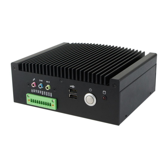
Page 14: Overview
1.6 Overview Front View No. Name Name Digital I/O Connector USB 2.0 Ports Microphone Input Power Button Line-In HDD LED Indicator Line-Out ASB200-915 User Manual... - Page 15 General Information Rear View No. Name Name Antenna Holes USB 3.1 Type-C COM1 (RJ50) RS-232/422/485 DC-In Power Connector Port COM2 / COM3 / COM4 (DB-9) DisplayPort RS-232 Ports LAN Ports (GbE) Wall Mount Kit USB 3.0 Ports ASB200-915 User Manual...
- Page 16 Oblique View ASB200-915 User Manual...
-
Page 17: Dimensions
General Information 1.7 Dimensions Unit: mm ASB200-915 User Manual... -
Page 18: Chapter 2 Hardware Configuration
Chapter 2 Hardware Configuration The information provided in this chapter includes: • Essential installations before you begin • Information and locations of connectors... -
Page 19: Essential Installations Before You Begin
Hardware Configuration 2.1 Essential Installations Before You Begin Before installations, you need to disassemble the device cover by loosen 6 screws from the device and pull out the cover. ASB200-915 User Manual... -
Page 20: Hdd Installation
If you need to install or replace an SSD or a HDD, follow the instructions below for installation after you disassemble the device cover. 1. Loosen 4 screws below. 2. Attach your SSD / HDD and tighten these screws. ASB200-915 User Manual... -
Page 21: Memory Installation
Hardware Configuration 2.1.2 Memory Installation There are two SO-DIMM DDR3L memory slots inside ASB200-915 and the maximum memory is expandable up to 16 GB. If you need to install or replace a memory module, follow the instructions below. 1. Locate the memory slot on the board. -
Page 22: Mini-Pcie Card Installation
PCB bracket. 1. Align the key of the mini-PCIe card to the mini-PCIe interface, and insert the card slantwise. 2. Push the mini-PCIe card down, fix it onto the standoff with a screw. ASB200-915 User Manual... -
Page 23: Wifi / 3G / 4G Antenna Installation
WiFi / 3G / 4G Antenna Installation Thread the WiFi / 3G / 4G antenna cable through an antenna hole. Then fasten the antenna as shown below. Info: The diameter of the nut is around 6.35 mm (0.25”-36UNC). ASB200-915 User Manual... -
Page 24: Device Exploded Diagram
2.1.5 Device Exploded Diagram ASB200-915 User Manual... - Page 25 Screw (M3*6) 2.5” HDD Power Button LED Spacer Support Gasket_ID112 Screw (UNC #6-32*6) Screw (M2*6) Terminal Block (10P) Screw (UNC #4-40*10) Base Wall Mount Bracket Screw (M3*4) Audio Cable COM Cable Gasket_DP Gasket_USB Rear Plate Terminal Block (3P) ASB200-915 User Manual...
-
Page 26: Wall Mount Installation
When mounting, ensure that you have enough room for power and signal cable routing, and have good ventilation for power adapter. The method of mounting must be able to support weight of the ASB200-915 plus the suspension weight of all the cables to be attached to the system. Use the... - Page 27 Hardware Configuration Wall mount installation instructions: 1. Attach the mounting brackets to your ASB200-915, and secure with the supplied 4 screws. 2. Prepare at least 4 screws (M3) to install the device on wall . You can install ASB200-915 on plastic (LCD monitor), wood, drywall surface over studs, or a solid concrete or metal plane directly.
-
Page 28: Vesa Mount Installation
2.1.7 VESA Mount Installation 1. VESA mounting ASB200-915 ASB200-915 User Manual... - Page 29 Hardware Configuration 2. VESA mounting ASB200-915 to a panel ASB200-915 User Manual...
-
Page 30: Pinout For Com Ports, Dc Power & Digital I/O Connectors
DCD, Data carrier detect Ground DTR, Data terminal ready Ground CTS, Clear to send TXD, Transmit data RTS, Request to send RXD, Receive data RI, Ring indicator Assignment RS-232 RS-422 RS-485 Ground Ground Ground Ground Ground Ground Data+ Data- ASB200-915 User Manual... - Page 31 TXD, Transmit data CTS, Clear to send DTR, Data terminal ready RI, Ring indicator Ground • DC Power Input Connector (terminal block) Assigment Assigment Ground +12V Chassis Ground • Digital I/O Connector (terminal block) Assigment Assigment Ground ASB200-915 User Manual...
-
Page 32: Setting The Jumpers
2.2 Setting the Jumpers Set up and configure your ASB200-915 by using jumpers for various settings and features according to your needs and applications. Contact your supplier if you have doubts about the best configuration for your use. 2.2.1 How to Set Jumpers Jumpers are short-length conductors consisting of several metal pins with a non-conductive base mounted on the circuit board. -
Page 33: Jumper & Connector Locations On Motherboard
Hardware Configuration 2.3 Jumper & Connector Locations on Motherboard Motherboard: IB915AF 9 10 9 10 J1 J2 IB915AF - top ASB200-915 User Manual... - Page 34 Intel ® Gen. Core™ i3 / i5 / i7 U-series IB915AF - bottom ASB200-915 User Manual...
-
Page 35: Jumpers Quick Reference
LVDS Panel Brightness Control Selection LVDS Panel Power Selection J2, JP6 ME Register Clearance CMOS Data Clearance Factory Use Only JP4, JP5 2.4.1 LVDS Panel Brightness Control Selection (JP1) Function Pin closed Illustration 3.3V Open Close (default) ASB200-915 User Manual... -
Page 36: Lvds Panel Power Selection (J2, Jp6)
2.4.2 LVDS Panel Power Selection (J2, JP6) Function Pin closed Illustration 3.3V (default) JP6: Function Pin closed Illustration 3.3V (default) ASB200-915 User Manual... -
Page 37: Me Register Clearance (J7)
Hardware Configuration 2.4.3 ME Register Clearance (J7) Function Pin closed Illustration Normal (default) Clear ME 2.4.4 CMOS Data Clearance (J8) Function Pin closed Illustration Normal (default) Clear CMOS ASB200-915 User Manual... -
Page 38: Connectors Quick Reference
DDR3L SO-DIMM Slot J6, J11 Battery Connector SATA HDD Power Connector Mini-PCIe / mSATA Slot COM3 & COM4 Connectors J14, J17 Front Panel Function Connector COM2 Connector Digital I/O Connector DC-In Connector Factory Use Only J1, J12 ASB200-915 User Manual... -
Page 39: Sata Iii Connector (Cn1, Cn2)
Hardware Configuration 2.5.1 SATA III Connector (CN1, CN2) 2.5.2 Dual LAN Ports (GbE) (CN3) 2.5.3 eDP Connector (CN4) ASB200-915 User Manual... -
Page 40: Usb 3.0 Connector (Cn5, Cn6)
2.5.4 USB 3.0 Connector (CN5, CN6) 2.5.5 COM1 (RJ50) RS-232/422/485 Port (CN7) 2.5.6 DisplayPort (CN8) ASB200-915 User Manual... -
Page 41: Usb 3.1 Type-C Port (Cn9)
Hardware Configuration 2.5.7 USB 3.1 Type-C Port (CN9) 2.5.8 LCD Backlight Connector (JP2) Assigment Assigment Brightness Control Backlight Enable Ground ASB200-915 User Manual... -
Page 42: Usb 2.0 Connector (Jp3)
2.5.9 USB 2.0 Connector (JP3) Assigment Assigment Ground Ground 2.5.10 Audio Connector (J5) Assigment Assigment LINEOUT_L JD_LINEIN LINEOUT_R Ground JD_FRONT MIC_L Ground MIC-R LINEIN_L JD_MIC1 LINEIN_R Ground ASB200-915 User Manual... -
Page 43: Lvds Connector (J3, J4)
Hardware Configuration 2.5.11 LVDS Connector (J3, J4) J3: 2 channel J4: 1 channel Assigment Assigment TX0P Ground TX0N Ground Ground CLKP Ground CLKN TX1P Ground TX1N Ground Ground TX3P Ground TX3N TX2P Power TX2N Power ASB200-915 User Manual... -
Page 44: Ddr3L So-Dimm Slot (J6, J11)
2.5.12 DDR3L SO-DIMM Slot (J6, J11) 2.5.13 Battery Connector (J9) Assigment Battery+ Ground ASB200-915 User Manual... -
Page 45: Sata Hdd Power Connector (J10)
Hardware Configuration 2.5.14 SATA HDD Power Connector (J10) Assigment Assigment Ground Ground +12V 2.5.15 Mini-PCIe / mSATA Slot (J13) ASB200-915 User Manual... -
Page 46: Com3 & Com4 Connectors (J14, J17)
RTS, Request to send TXD, Transmit data CTS, Clear to send DTR, Data terminal ready RI, Ring indicator Ground Not used 2.5.17 Front Panel Function Connector (J15) Assigment Assigment Ground Ground PWR_BTN Reset 3.3V HDD Active Ground ASB200-915 User Manual... -
Page 47: Com2 Connector (J16)
DSR, Data set ready RXD, Receive data RTS, Request to send TXD, Transmit data CTS, Clear to send DTR, Data terminal ready RI, Ring indicator Ground Not Used 2.5.19 Digital I/O Connector (J18) Assigment Assigment Ground OUT0 OUT3 OUT1 OUT2 ASB200-915 User Manual... -
Page 48: Dc-In Connector (J19)
2.5.20 DC-In Connector (J19) Assigment 9V ~ 24V Ground ASB200-915 User Manual... -
Page 49: Chapter 3 Driver Installation
Chapter 3 Driver Installation The information provided in this chapter includes: • ® Intel Chipset Software Installation Utility • VGA Driver Installation • HD Audio Driver Installation • LAN Driver Installation • ® Intel Management Engine Driver Installation • USB 3.0 Driver Installation •... -
Page 50: Introduction
If you find anything missing, please contact the distributor where you made the purchase. Note: After installing your Windows operating system, you must install the ® Intel Chipset Software Installation Utility first before proceeding with the drivers installation. ASB200-915 User Manual... -
Page 51: Intel Chipset Software Installation Utility
4. Click Yes to accept the software license agreement and proceed with the installation process. 5. On the Readme File Information screen, click Next for installation. 6. The driver has been completely installed. You are suggested to restart the computerfor changes to take effect. ASB200-915 User Manual... -
Page 52: Vga Driver Installation
3.3 VGA Driver Installation 1. Insert the disk enclosed in the package. Click Intel and then Intel(R) Skylake-U Chipset Drivers. 2. Click Intel(R) HD Graphics Driver. ASB200-915 User Manual... - Page 53 3. When the Welcome screen appears, click Next to continue. 4. Click Yes to agree with the license agreement and click Install for installation. 5. The driver has been completely installed. You are suggested to restart the computer for changes to take effect. ASB200-915 User Manual...
-
Page 54: Hd Audio Driver Installation
3.4 HD Audio Driver Installation 1. Insert the disk enclosed in the package. Click Intel and then Intel(R) Skylate-U Chipset Drivers. 2. Click Realtek High Definition Audio Driver. ASB200-915 User Manual... - Page 55 Driver Installation 3. On the Welcome screen of the InstallShield Wizard, click Next for installation. 4. The driver has been completely installed. You are suggested to restart the computer for changes to take effect. ASB200-915 User Manual...
-
Page 56: Lan Driver Installation
3.5 LAN Driver Installation 1. Insert the disk enclosed in the package with the product. Click LAN Card and then Intel(R) Skylake-U Chipset Drivers 2. Click Intel(R) PRO LAN Network Drivers.. ASB200-915 User Manual... - Page 57 Driver Installation 3. Click Install Drivers and Software.. 4. When the Welcome screen appears, click Next to continue. 5. Accept the license agreement and click Next to continue. ASB200-915 User Manual...
- Page 58 6. Tick the checkbox for Drivers to select the related drivers and click Next. 7. When the wizard is ready for installation, click Install. 8. The driver has been completely installed. You are suggested to restart the computer for changes to take effect. ASB200-915 User Manual...
-
Page 59: Intel Management Engine Driver Installation
Driver Installation ® 3.6 Intel Management Engine Driver Installation 1. Insert the disk enclosed in the package. Click Intel and then Intel(R) Skylake-U Chipset Drivers. 2. Click Intel(R) ME 11.x Drivers. ASB200-915 User Manual... - Page 60 3. When the Welcome screen appears, click Next to continue. 4. Accept the licence agreement and click Next to continue. 5. The driver has been completely installed. You are suggested to restart the computer for changes to take effect. ASB200-915 User Manual...
-
Page 61: Usb 3.0 Driver Installation
Driver Installation 3.7 USB 3.0 Driver Installation 1. Insert the disk enclosed in the package. Click Intel and then Intel(R) Skylake-U Chipset Drivers. 2. Click Intel(R) USB 3.0 Drivers. ASB200-915 User Manual... - Page 62 4. Accept the license agreement and click Next to continue. 5. On the Readme File Information screen, click Next for installation. 6. The driver has been completely installed. You are suggested to restart the computer for changes to take effect. ASB200-915 User Manual...
-
Page 63: Usb 3.1 Driver Installation
Driver Installation 3.8 USB 3.1 Driver Installation 1. Insert the disk enclosed in the package. Click Intel and then Intel(R) Skylake-U Chipset Drivers. 2. Click ASMedia USB 3.1 Drivers. ASB200-915 User Manual... - Page 64 3. When the Welcome screen appears, click Next to continue. 4. The driver has been completely installed. You are suggested to restart the computer for changes to take effect. ASB200-915 User Manual...
-
Page 65: Chapter 4 Bios Setup
Chapter 4 BIOS Setup This chapter the different settings available in the AMI describes BIOS that comes with the board. The topics covered in this chapter are as follows: • Main Settings • Advanced Settings • Chipset Settings • Security Settings •... -
Page 66: Introduction
These defaults have been carefully chosen by both AMI and your system manufacturer to provide the absolute maximum performance and reliability. Changing the defaults could make the system unstable and crash in some cases. ASB200-915 User Manual... -
Page 67: Main Settings
System Language Choose the system default language. System Date Sets the date. Use the <Tab> key to switch between the data elements. System Time Set the time. Use the <Tab> key to switch between the data elements. ASB200-915 User Manual... -
Page 68: Advanced Settings
4.4 Advanced Settings This section allows you to configure, improve your system and allows you to set up some system features according to your preference. ASB200-915 User Manual... -
Page 69: Acpi Settings
ACPI Sleep State Selects a ACPI sleep state for the system to enter. Options: Suspend Disabled S3 (Suspend to RAM) Lock Legacy Resources Enables / Disables Lock of Legacy Resources. S3 Video Repost Enables / Disables S3 Video Repost. ASB200-915 User Manual... -
Page 70: Lvds (Edp/Dp) Configuration
Options: • 800 x 600 • 1024 x 768 • 1366 x 768 • 1440 x 900 • 1600 x 900 • 1280 x 1024 • 1920 x 1080 Brightness Control Enables / Disables the brightness control. ASB200-915 User Manual... -
Page 71: Ismart Controller
Controller BIOS Setting Description Power-On after Power Enables / Disables the system to be turned on failure automatically after a power failure. Power Resume Delay Enables / Disables to delay the time for system to turn on. ASB200-915 User Manual... - Page 72 Generate the reset signal when system hands up on POST. Schedule Slot 1 / 2 Sets up the hour / minute / day for the power- on schedule for the system. Options: • None • Power On • Power On / Off ASB200-915 User Manual...
-
Page 73: Amt Configuration
Sets timer to wait before sending ASF_GET_BOOT_OPTIONS. Active Remote Triggers CIRA boot. Assistance Process USB Configure Enables / Disables USB configure function. PET Progress Enables / Disables PET events progress to receive PET events or not. WatchDog Enables / Disables watchdog timer. ASB200-915 User Manual... -
Page 74: Fintek Super Io Configuration
4.4.5 Fintek Super IO Configuration BIOS Setting Description Serial Port Configuration Sets Parameters of Serial Ports. You can enable / disable the serial port and select an optimal settings for the Super IO device. ASB200-915 User Manual... - Page 75 IO=2E8h ; IRQ=3, 4, 5, 6, 7, 9. 10, 11, 12 Device Mode Changes the mode of serial port. Options: • RS232 • RS485 TX Low Active • RS485 with Termination TX Low Active • RS422 with Termination ASB200-915 User Manual...
- Page 76 IO=3F8h ; IRQ=3, 4, 5, 6, 7, 9. 10, 11, 12 • IO=2F8h ; IRQ=3, 4, 5, 6, 7, 9. 10, 11, 12 • IO=3E8h ; IRQ=3, 4, 5, 6, 7, 9. 10, 11, 12 • IO=2E8h ; IRQ=3, 4, 5, 6, 7, 9. 10, 11, 12 ASB200-915 User Manual...
- Page 77 IO=3E8h ; IRQ=3, 4, 5, 6, 7, 9. 10, 11, 12 • IO=2E8h ; IRQ=3, 4, 5, 6, 7, 9. 10, 11, 12 • IO=2F0h ; IRQ=3, 4, 5, 6, 7, 9. 10, 11, 12 • IO=2E0h ; IRQ=3, 4, 5, 6, 7, 9. 10, 11, 12 ASB200-915 User Manual...
- Page 78 IO=3E8h ; IRQ=3, 4, 5, 6, 7, 9. 10, 11, 12 • IO=2E8h ; IRQ=3, 4, 5, 6, 7, 9. 10, 11, 12 • IO=2F0h ; IRQ=3, 4, 5, 6, 7, 9. 10, 11, 12 • IO=2E0h ; IRQ=3, 4, 5, 6, 7, 9. 10, 11, 12 ASB200-915 User Manual...
-
Page 79: Fintek Hardware Monitor
80 ℃, 85 ℃, 90 ℃, 95 ℃ Temperatures / Voltages These fields are the parameters of the hardware monitoring function feature of the motherboard. The values are read-only as monitored by the system and showing the PC health status ASB200-915 User Manual... -
Page 80: Cpu Configuration
4.4.7 CPU Configuration BIOS Setting Description Intel(R) SpeedStep (tm) Enables / Disables the function to allow more than two frequency ranges to be supported. Turbo Mode Enables / Disables Turbo Mode. ASB200-915 User Manual... -
Page 81: Sata Configuration
Selects the SATA controller speed as Default / Gen1 / Gen2 / Gen3. Serial ATA Port 0~5 Enables / Disables Serial Port 0 ~ 5. SATA Port 0 ~ 5 HotPlug Enables / Disables SATA Port 0 ~ 5 HotPlug. ASB200-915 User Manual... -
Page 82: Csm Configuration
PXE OpROM. Storage Controls the execution of UEFI and Legacy Storage OpROM. Video Controls the execution of UEFI and Legacy Video OpROM. Other PCI devices Determines OpROM execution policy for devices other than network, storage or video. ASB200-915 User Manual... -
Page 83: Usb Configuration
Sets the time-out value 1, 5, 10 or 20 sec(s) for Control, Bulk, and Interrupt transfers. Device reset time-out Sets the seconds (10, 20, 30, 40 secs) of delaying execution of start unit command to USB mass storage device. ASB200-915 User Manual... - Page 84 The maximum time the device will take before it properly reports itself to the Host Controller. Auto uses default value. For a Root port, it is 100 ms. For a Hub port, the delay is taken from Hub descriptor. ASB200-915 User Manual...
-
Page 85: Chipset Settings
BIOS Setup 4.5 Chipset Settings ASB200-915 User Manual... -
Page 86: System Agent (Sa) Configuration
Options: Auto, PCIE1 ~ PCIE19 Internal Graphics Enables / Disables the interal graphics. Keep IGFX enabled according to the setup options. Options: Auto, Disabled, Enabled GTT Size Selects the size of GTT as 2 / 4 / 8 MB. ASB200-915 User Manual... - Page 87 POST. This has no effect if external graphics present. Secondary boot display selection will appear based on your selection. VGA modes will be supported only on primary display. Options: VBIO Default, CRT, EFP, LFP, EFP3, EFP2, LFP2 ASB200-915 User Manual...
- Page 88 Hardware: Spread is controlled by chip. • Software: Spread is controlled by BIOS. Active LFP Configures the LFP usage. Options: No LVDS, eDP Port A, eDP Port D Panel Color Depth Selects the LFP panel color depth as 18 or 24 bit. ASB200-915 User Manual...
-
Page 89: Pch-Io Configuration
Wake on LAN Enables / Disables integrated LAN to wake the system. (The Wake on LAN cannot be disabled if ME is at Sx state.) SLP_LAN# Low on DC Enables / Disables SLP_LAN# Low on DC Power Power. ASB200-915 User Manual... -
Page 90: Security Settings
4.6 Security Settings BIOS Setting Description Administrator Password Sets an administrator password for the setup utility. User Password Sets a user password. ASB200-915 User Manual... -
Page 91: Boot Settings
Sets the system boot order priorities for hard disk, CD/DVD, USB, Network. Option ROM Messages Sets a display mode, Force BIOS or Keep Current, for Option ROM. Interrupt 19 Capture Allows Option ROMs to trap Interrupt 19. ASB200-915 User Manual... -
Page 92: Save & Exit Settings
Restore Defaults Restores / Loads defaults values for all the setup options. Save as User Defaults Saves the changes done so far as user defaults. Restore User Defaults Restores the user defaults to all the setup options. ASB200-915 User Manual... -
Page 93: Appendix
Appendix This section provides the mapping addresses of peripheral devices and the sample code of watchdog timer configuration. • I/O Port Address Map • Interrupt Request Lines (IRQ) • Watchdog Timer Configuration... -
Page 94: I/O Port Address Map
Programmable interrupt controller 0x000004D0-0x000004D1 Programmable interrupt controller 0x00000A00-0x00000A0F Motherboard resources 0x00000A10-0x00000A1F Motherboard resources 0x00000A20-0x00000A2F Motherboard resources 0x0000002E-0x0000002F Motherboard resources 0x0000004E-0x0000004F Motherboard resources 0x00000061-0x00000061 Motherboard resources 0x00000063-0x00000063 Motherboard resources 0x00000065-0x00000065 Motherboard resources 0x00000067-0x00000067 Motherboard resources 0x00000070-0x00000070 Motherboard resources ASB200-915 User Manual... - Page 95 Intel(R) 100 Series Chipset Family PCI Express Root Port #11 - 9D1A 0x0000F040-0x0000F05F Intel(R) 100 Series Chipset Family SMBUS - 9D23 0x0000FF00-0x0000FFFE Motherboard resources 0x00000060-0x00000060 Standard PS/2 Keyboard 0x00000064-0x00000064 Standard PS/2 Keyboard 0x0000F090-0x0000F097 Standard SATA AHCI Controller ASB200-915 User Manual...
- Page 96 Address Device Description 0x0000F080-0x0000F083 Standard SATA AHCI Controller 0x0000F060-0x0000F07F Standard SATA AHCI Controller ASB200-915 User Manual...
-
Page 97: Interrupt Request Lines (Irq)
IRQ 4294967287 Intel(R) I211 Gigabit Network Connection IRQ 4294967288 ASMedia USB3.1 eXtensible Host Controller IRQ 4294967289 Intel(R) USB 3.0 eXtensible Host Controller - 1.0 (Microsoft) IRQ 4294967290 Intel(R) HD Graphics 520 IRQ 4294967291 Intel(R) Ethernet Connection I219-LM ASB200-915 User Manual... - Page 98 Level Function IRQ 4294967292 Standard SATA AHCI Controller IRQ 4294967293 Intel(R) 100 Series Chipset Family PCI Express Root Port #11 - 9D1A IRQ 4294967294 Intel(R) 100 Series Chipset Family PCI Express Root Port #1 - 9D10 ASB200-915 User Manual...
-
Page 99: Watchdog Timer Configuration
**endptr; char SIO; printf("Fintek 81866 watch dog program\n"); SIO = Init_F81866(); if (SIO == 0) printf("Can not detect Fintek 81866, program abort.\n"); return(1); }//if (SIO == 0) if (argc != 2) printf(" Parameter incorrect!!\n"); return (1); ASB200-915 User Manual... - Page 100 //--------------------------------------------------------------------------- void DisableWDT(void) unsigned char bBuf; Set_F81866_LD(0x07); //switch to logic device 7 bBuf = Get_F81866_Reg(0xFA); bBuf &= ~0x01; Set_F81866_Reg(0xFA, bBuf); //disable WDTO output bBuf = Get_F81866_Reg(0xF5); bBuf &= ~0x20; bBuf |= 0x40; Set_F81866_Reg(0xF5, bBuf); //disable WDT //--------------------------------------------------------------------------- ASB200-915 User Manual...
- Page 101 (ucDid == 0x07) //Fintek 81866 goto Init_Finish; } F81866_BASE = 0x00; result = F81866_BASE; Init_Finish: return (result); //--------------------------------------------------------------------------- void Unlock_F81866 (void) outportb(F81866_INDEX_PORT, F81866_UNLOCK); outportb(F81866_INDEX_PORT, F81866_UNLOCK); //--------------------------------------------------------------------------- void Lock_F81866 (void) outportb(F81866_INDEX_PORT, F81866_LOCK); //--------------------------------------------------------------------------- void Set_F81866_LD( unsigned char LD) Unlock_F81866(); ASB200-915 User Manual...
- Page 102 #define F81866_DATA_PORT (F81866_BASE+1) //--------------------------------------------------------------------------- #define F81866_REG_LD 0x07 //--------------------------------------------------------------------------- #define F81866_UNLOCK 0x87 #define F81866_LOCK 0xAA //--------------------------------------------------------------------------- unsigned int Init_F81866(void); void Set_F81866_LD( unsigned char); void Set_F81866_Reg( unsigned char, unsigned char); unsigned char Get_F81866_Reg( unsigned char); //--------------------------------------------------------------------------- #endif // F81866_H ASB200-915 User Manual...
Need help?
Do you have a question about the ASB200-915 and is the answer not in the manual?
Questions and answers