Table of Contents
Advertisement
Quick Links
Advertisement
Table of Contents

Related Manuals for IBASE Technology IBT200 Series


Summary of Contents for IBASE Technology IBT200 Series
- Page 1 IBT200 Series User Manual 2008 November V1.0...
- Page 2 Copyright © 2008 IBASE Technology INC. All Rights Reserved. No part of this manual, including the products and software described in it, may be reproduced, transmitted, transcribed, stored in a retrieval system, or translated into any language in any form or by any means, except documentation kept by the purchaser for backup purposes, without the express written permission of IBASE Technology INC.
-
Page 3: Table Of Contents
Table of Contents Accessories ......................6 Components ......................7 Front View ........................7 Rear View (AMI200-9) ....................8 Rear View (AMI200-8) ....................10 Specification ......................12 Mounting AMI200 to the Wall ................13 Wall mounting requirements ..................13 Selecting the location ....................14 Exploded view of the AMI200 assembly –... - Page 4 Safety Information Your AMI200-8/9 is designed and tested to meet the latest standards of safety for information technology equipment. However, to ensure your safety, it is important that you read the following safety instructions. Setting up your system • Read and follow all instructions in the documentation before you operate your system.
- Page 5 The system was dropped or the cabinet is damaged. Lithium-Ion Battery Warning CAUTION: Danger of explosion if battery is incorrectly replaced. Replace only with the same or equivalent type recommended by the manufacturer. Dispose of used batteries according to the manufacturer’s instructions. NO DISASSEMBLY The warranty does not apply to the products that have been disassembled by users...
-
Page 6: Accessories
Accessories Power Cord x 1 M/B Manual x 1 Driver CD x 1 Power Brick x 1 Mounting Rail Screw x 6 Mounting Rail x 2... -
Page 7: Components
Components Front View Refer to the diagram below to identify the components on this side of the system. The power LED illuminated when system been power on. The hard disk LED blinks when data is being written into or read from the hard disk drive. -
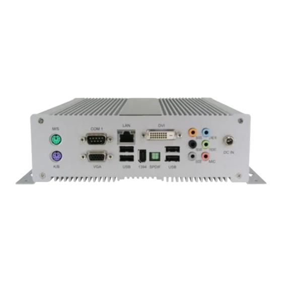
Page 8: Rear View (Ami200-9)
Rear View (AMI200-9) Refer to the diagram below to identify the components on this side of the system. The PS/2 mouse port is use to connect PS/2 mouse. The PS/2 keyboard port is use to connect PS/2 compatible devices such as keyboard, MSR and scanner. - Page 9 The Digital Visual Interface (DVI) port supports a high quality VGA-compatible device such as a monitor or projector to allow viewing on a larger external display. SPDIF Plug a standard SPDIF optical audio cable into this connector for digital audio transfer.
-
Page 10: Rear View (Ami200-8)
Rear View (AMI200-8) Refer to the diagram below to identify the components on this side of the system. The PS/2 mouse port is use to connect PS/2 mouse. The PS/2 keyboard port is use to connect PS/2 compatible devices such as keyboard, MSR and scanner. - Page 11 The eight-pin RJ-45 LAN port supports a standard Ethernet cable for connection to a local network. The USB (Universal Serial Bus) port is compatible with USB devices such as keyboards, mouse devices, cameras, and hard disk drives. USB allows many devices to run simultaneously on a single computer, with some peripheral acting as additional plug-in sites or hubs.
-
Page 12: Specification
Specification System Mainboard MI910E / MB899EF Construction Aluminum Chassis Color Silver Storage 2.5” 80GB SATA HDD x 1 Mounting Desktop or wall mount Dimensions 199(W) x 63.4(H) x 232(D)mm (7.83” x 2.57” x 9.13”) Power Supply 80W DC adapter Operating 0°C ~ 45°C (32°F ~ 113°F) Temperature Storage... -
Page 13: Mounting Ami200 To The Wall
Mounting AMI200 to the Wall Using attached mounting rail, you can install AMI200 on wood, drywall surface over studs, or a solid concrete or metal plane. Ensure the installer uses at least four M4 length 8mm screws to secure the system on wall. Six M4 length 8mm screws are recommended to secure the system on wall. -
Page 14: Selecting The Location
routing. And have good ventilation for power adapter. The method of mounting must be able to support weight of the AMI200 plus the suspend weight of all the cables to be attached to the system. Use the following methods for mounting your system: Mounting to hollow walls ... -
Page 15: Exploded View Of The Ami200 Assembly - Ami200-9
Exploded view of the AMI200 assembly – AMI200-9... -
Page 16: Parts Description
Parts description Part NO. Description Part NO. Description 1 HDD 2 HDD bracket rubber foot 3 Screws for SB heat sink 4 ID392 DVI board 5 MI910E 6 CPU FAN bracket 7 Bottom chassis 8 Rear panel 9 DC extension cable 10 Name panel 11 Top chassis 12 SATA signal cable... -
Page 17: Exploded View Of The Ami200 Assembly - Ami200-8
Exploded view of the AMI200 assembly – AMI200-8... -
Page 18: Parts Description
Parts Description Part NO. Description Part NO. Description 1 HDD 2 HDD bracket rubber foot 3 MB899EF 4 CPU FAN bracket 5 Bottom chassis 6 Rear panel 7 DC extension cable 8 Name panel 9 Top chassis 10 SATA signal cable 11 SATA power cable 12 HDD bracket 13 Anti-Vibrate grommet... -
Page 19: Driver Installation
Driver Installation Please refer correspond mainboard user manual to install the driver properly. BIOS Setup Please refer correspond mainboard user manual to configure BIOS setting.
Need help?
Do you have a question about the IBT200 Series and is the answer not in the manual?
Questions and answers