Advertisement
AXI 22 AT D Plus • Setup Guide
IMPORTANT NOTE:
Go to
www.extron.com
product to the power source.
This guide provides basic instructions for an experienced technician to
inOkaystall the AXI 22 AT D Plus.
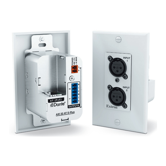
The Extron AXI 22 AT D Plus Dante Audio Interface is a one-gang
Decorator-style audio interface for integrating two mic/line sources into a
Dante™ enabled audio system. It has two XLR audio inputs with software
configurable gain controls and +48 VDC phantom power for each input.
It features two line outputs for routing any two Dante channels from the
network to ancillary audio equipment such as an amplifier or recording
device, or for connecting to an optional wallplate with two XLR outputs.
This guide provides the necessary information for an experienced technician
to install the AXI 22 AT D Plus. For additional information and specifications,
see the AXI 22 AT D Plus product page at www.extron.com.
Disconnect Power and Mount the AXI 22 AT D Plus
Before beginning installation, disconnect power and turn off all devices that will be connected to the AXI 22 AT D Plus. The AXI 22 AT D Plus
can be installed wherever desired. There is no need for a dedicated power source if the attached Ethernet cable carries PoE to the
AXI 22 AT D Plus. Select a suitable mounting location, then choose an appropriate mounting option (see the instructions provided with the
chosen mounting option).
Rear Panel Connections
C C C
AT (PoE)
OUTPUTS
AXI 22 AT D Plus
Rear
Figure 1.
AXI 22 AT D Plus Rear Panel
DC Power
DC Power Cord
Input
Captive Screw Connector
Figure 2.
External Power Supply Connection
for the complete user guide, installation instructions, and specifications before connecting the
A A A
C C C
B B B
Top
Ground all
Devices
Ridged
Ground
G
+12 VDC input
Smooth
12 VDC power input
A
Line output 1 and Line output 2
B
RJ-45 AT (PoE) port
C
12 VDC power input – Connect an optional 12 VDC power
A
supply to the rear panel captive screw input and plug the power
cord into the IEC connector on the power supply.
The amber power LEDs behind the front panel blink while the
unit is booting. They turn off when the device is ready and
connected to a network. If a network connection is not detected,
the LEDs light steady until a network connection is achieved.
Wire the 12 VDC power supply as shown in figure 2.
Alternatively, the AXI 22 AT D Plus can be powered over
Ethernet (PoE) using the AT (PoE) port (
AXI 22 AT D Plus User Guide).
External Power Supply
(12 VDC, 0.5 A max.)
) (see the
C
1
Advertisement
Table of Contents

Related Manuals for Extron electronics AXI 22 AT D Plus


Summary of Contents for Extron electronics AXI 22 AT D Plus
- Page 1 Disconnect Power and Mount the AXI 22 AT D Plus Before beginning installation, disconnect power and turn off all devices that will be connected to the AXI 22 AT D Plus. The AXI 22 AT D Plus can be installed wherever desired. There is no need for a dedicated power source if the attached Ethernet cable carries PoE to the AXI 22 AT D Plus.
- Page 2 CSR 6 Wiring Diagram RJ-45 AT (PoE) port — Insert an Ethernet cable into this RJ-45 port to connect the AXI 22 AT D Plus to a Dante network. This port supports Power over Ethernet (PoE), communication with DSP Configurator for configuration, digital audio transport (AT), and communication with the Dante/AES67 network for configuration via Dante Controller, which simultaneously transmits and receives a maximum of two Dante audio flows.
-
Page 3: Downloading And Installing Dante Controller Software
Amber LEDs light when power is provided. The LED blinks while the A A A INPUT AXI 22 AT D Plus is booting up and is off when boot-up is complete. It lights steadily if there is no network connection. •... -
Page 4: Creating A Physical Dante Network
Dante Controller - Device View dialog NOTE: If the AXI 22 AT D Plus has not been renamed, the default name consists of the product name followed by a hyphen AXI22DP- ) plus the last 6-digits of the unit MAC address (for example,... -
Page 5: Finding A Dante Device Ip Address
( ). Device names follow Domain Name System (DNS) hostname rules (refer to the Dante Controller section of the AXI 22 AT D Plus User Guide for a full list of device name rules). Click Apply ). -
Page 6: Routing Transmitters And Receivers
Downloading and Installing DSP Configurator Software The AXI 22 AT D Plus can be controlled with Extron DSP Configurator software using the USB or AT ports, or DataViewer using the USB port. Install DSP Configurator on a PC running Microsoft Windows .
Need help?
Do you have a question about the AXI 22 AT D Plus and is the answer not in the manual?
Questions and answers