Sign In
Upload
Download
Table of Contents
Contents
Add to my manuals
Delete from my manuals
Share
URL of this page:
HTML Link:
Bookmark this page
Add
Manual will be automatically added to "My Manuals"
Print this page
×
Bookmark added
×
Added to my manuals
Manuals
Brands
Martin Manuals
DJ Equipment
LC 2140
User manual
Martin LC 2140 User Manual
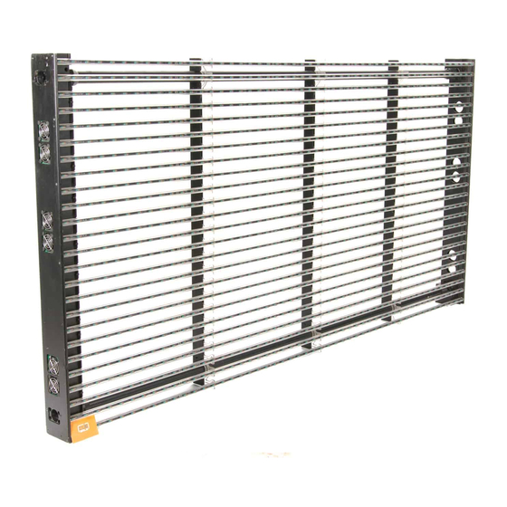
Led video screen
Hide thumbs
1
2
3
4
5
Table Of Contents
6
7
8
9
10
11
12
13
14
15
16
17
18
19
20
21
22
23
24
25
26
27
28
29
30
31
32
33
34
35
36
page
of
36
Go
/
36
Contents
Table of Contents
Troubleshooting
Bookmarks
Table of Contents
Dimensions
Safety Information
Table of Contents
Connections Panel Overview
Introduction
Unpacking
Using for the First Time
Packing Panels in the Flightcase
Physical Installation
Standing Installation
Flying from a Truss, Bar or Other Structure
Diffuser
Single LED Tubes
AC Power
Power and Main Fuses
Power Connection
Video Link
Planning the Video Link
Connecting the Video Link
Panel Setup
Tips for Panel Addressing
Advanced Setup
Operation
Service and Maintenance
Cleaning
Fuse Replacement
Replacing LED Tubes
Installing New Software
Troubleshooting
LC 1140/2140 Specifications
Advertisement
Quick Links
Download this manual
LC 1140/2140
LED Video Screen
user manual
Table of
Contents
Previous
Page
Next
Page
1
2
3
4
5
Advertisement
Table of Contents
Need help?
Do you have a question about the LC 2140 and is the answer not in the manual?
Ask a question
Questions and answers
Related Manuals for Martin LC 2140
DJ Equipment Martin LC 1140 User Manual
Led video screen (36 pages)
DJ Equipment Martin RUSH Club Smoke Dual User Manual
(32 pages)
DJ Equipment Martin MAC 600 User Manual
(28 pages)
DJ Equipment Martin JEM ZR25 User Manual
Jem zr series (30 pages)
DJ Equipment Martin M-Series Reference Manual
Lighting controller (25 pages)
DJ Equipment Martin MAC Encore Performance CLD User Manual
(36 pages)
DJ Equipment Martin THRILL User Manual
Compact par mini led (2 pages)
DJ Equipment Martin MAC Aura XB Service Manual
(27 pages)
DJ Equipment Martin ELP WW LED Profile User Manual
(32 pages)
DJ Equipment Martin MAC Quantum Profile User Manual
(33 pages)
DJ Equipment Martin RUSH MH 7 Hybrid User Manual
(49 pages)
DJ Equipment Martin Atomic 3000 LED Service Manual
(20 pages)
DJ Equipment Martin Exterior Projection 500 Service Manual
(32 pages)
DJ Equipment Martin JEM Glaciator X-Stream Service Manual
(24 pages)
DJ Equipment Martin MAC Allure Wash PC User Manual
(34 pages)
DJ Equipment Martin MX-10 User Manual
(36 pages)
This manual is also suitable for:
Lc 1140
Table of Contents
Print
Rename the bookmark
Delete bookmark?
Delete from my manuals?
Login
Sign In
OR
Sign in with Facebook
Sign in with Google
Upload manual
Upload from disk
Upload from URL


Need help?
Do you have a question about the LC 2140 and is the answer not in the manual?
Questions and answers