
Subscribe to Our Youtube Channel
Related Manuals for GE Baker Hughes 2900-40 Series


Summary of Contents for GE Baker Hughes 2900-40 Series
- Page 1 Consolidated* 2900-40 Series Pilot Operated Safety Relief Valve Maintenance Manual (Rev. C) BHGE Data Classification : Public...
- Page 2 REFERENCE INFORMATION IN ADDITION TO THE CUSTOMER/OPERATOR’S NORMAL OPERATION AND MAINTENANCE PROCEDURES. SINCE OPERATION AND MAINTENANCE PHILOSOPHIES VARY, BHGE (BAKER HUGHES, A GE COMPANY AND ITS SUBSIDIARIES AND AFFILIATES) DOES NOT ATTEMPT TO DICTATE SPECIFIC PROCEDURES, BUT TO PROVIDE BASIC LIMITATIONS AND REQUIREMENTS CREATED BY THE TYPE OF EQUIPMENT PROVIDED.
- Page 3 Note 1: Multiply USCS value with conversion factor to get metric value. NOTICE! For valve configurations not listed in this manual, please contact your local Green Tag* Center for assistance. © 2019 Baker Hughes, a GE company. All Rights Reserved. Consolidated 2900-40 Series POSRV Maintenance Manual | 3...
-
Page 4: Table Of Contents
Lapping Disc Seats ........................................32 Precautions and Hints for Lapping Seats ................................. 34 G. Reconditioning of Laps ......................................34 H. Re-Machining Nozzle Seats ....................................34 Re-Machining the Disc Seat ....................................35 4 | BHGE © 2019 Baker Hughes, a GE company. All Rights Reserved. - Page 5 Backflow Preventer ........................................55 A.1 Disassembly Instructions ....................................55 A.2 Cleaning ..........................................55 A.3 Parts Inspection ......................................... 55 A.4 Reassembly Instructions ....................................55 © 2019 Baker Hughes, a GE company. All Rights Reserved. Consolidated 2900-40 Series POSRV Maintenance Manual | 5...
- Page 6 XXVII. Manufacture's Field Service, Repair, and Training Programs ......................... 75 Field Service ..........................................75 Factory Repair Facilities ......................................75 Safety Relief Valve Maintenance Training ................................ 75 End Users Notes ............................................. 76-79 6 | BHGE © 2019 Baker Hughes, a GE company. All Rights Reserved.
-
Page 7: Product Safety Sign And Label System
© 2019 Baker Hughes, a GE company. All Rights Reserved. Consolidated 2900-40 Series POSRV Maintenance Manual | 7... -
Page 8: Safety Alerts
Improper tools or improper All potential hazards use of right tools could may not be covered in result in personal injury or this manual. product damage. 8 | BHGE © 2019 Baker Hughes, a GE company. All Rights Reserved. - Page 9 Maintenance Manual, when correctly applied, will be effective. Wear necessary Always use appropriate protective equipment to restoration procedures. prevent possible injury © 2019 Baker Hughes, a GE company. All Rights Reserved. Consolidated 2900-40 Series POSRV Maintenance Manual | 9...
-
Page 10: Safety Notice
318/640-6054. Further, prior to working with the involved valves/equipment, personnel who are to perform such work should become thoroughly familiar with the contents of these instructions. 10 | BHGE © 2019 Baker Hughes, a GE company. All Rights Reserved. -
Page 11: Warranty Information
Note 1: Refer to BHGE’s Standard Terms of Sale for complete details on warranty and limitation of remedy and liability. Removal and/or breakage of seal will negate our warranty. © 2019 Baker Hughes, a GE company. All Rights Reserved. Consolidated 2900-40 Series POSRV Maintenance Manual | 11... -
Page 12: Terminology For Pilot Operated Safety Relief Valves
In gas or vapor service, the inlet pressure at gauge pressure permissible in a vessel at a designated which the valve pops determines the set pressure. temperature. A vessel may not be operated above this 12 | BHGE © 2019 Baker Hughes, a GE company. All Rights Reserved. -
Page 13: Handling And Storage
Never attempt to lift the valve by anything other than the eyebolts. © 2019 Baker Hughes, a GE company. All Rights Reserved. Consolidated 2900-40 Series POSRV Maintenance Manual | 13... -
Page 14: Pre-Installation And Installation Instructions
15-25 psi (1-1.5 bar). For pressures exceeding this limit, a Nitrogen bottle (connected to precautions must be taken the field test connector) precharged up to 97% of set pressure may be used. for the decontamination or cleaning method used. 14 | BHGE © 2019 Baker Hughes, a GE company. All Rights Reserved. -
Page 15: Introduction
51.78 3750 258.55 -20.0 262.8 Note: With the installation of the heat exchanger, temperature range may be expanded to 1200°F ( 648.9°C). © 2019 Baker Hughes, a GE company. All Rights Reserved. Consolidated 2900-40 Series POSRV Maintenance Manual | 15... -
Page 16: Consolidated 2900-40 Series Safety Relief Valves
Disc Retainer Disc Holder Guide Guide Gasket Guide Ring 1/2” NPT DRAIN Stud (Base) Nut (Base) Plug/Adaptor Plug/Adaptor Gasket Figure 1: 2900-40 Metal Seat Valve Construction Spring 16 | BHGE © 2019 Baker Hughes, a GE company. All Rights Reserved. -
Page 17: 2900-40 Main Valve (Soft Seat)
Figure 2: 2900-40 Soft Seat Valve Construction Part Nomenclature Nozzle Disc Disc Retainer Disc Holder Guide O-Ring Retainer Lock Screw O-Ring Retainer O-Ring Seat Seal © 2019 Baker Hughes, a GE company. All Rights Reserved. Consolidated 2900-40 Series POSRV Maintenance Manual | 17... -
Page 18: 39Pv Pilot Valve
Set Screw (Bonnet) Top Plate Note 1: Standard material is a filter HIGH PRESSURE plug. For special materials, vent assembly is supplied. Figure 3: 39PV Pilot Valve Construction 18 | BHGE © 2019 Baker Hughes, a GE company. All Rights Reserved. -
Page 19: Operating Principles
Since the area of the top of the piston is larger than the area of the seating surface, the differential area results in a net downward force keeping the main valve tightly closed. Figure 4: Pilot Valve (Closed) © 2019 Baker Hughes, a GE company. All Rights Reserved. Consolidated 2900-40 Series POSRV Maintenance Manual | 19... -
Page 20: Pv Valve Open (Relieving Position)
As the dome pressure equalizes with the inlet pressure, the downward force created by the differential areas of the piston and disc closes the main valve. Figure 5: Pilot Valve (Opened) 20 | BHGE © 2019 Baker Hughes, a GE company. All Rights Reserved. -
Page 21: General Planning For Maintenance
Position the POSRVs for easy access and/or removal so that servicing can be properly performed. Ensure sufficient working space is provided around and above the valve. © 2019 Baker Hughes, a GE company. All Rights Reserved. Consolidated 2900-40 Series POSRV Maintenance Manual | 21... -
Page 22: Inlet Piping
3% of the valve set pressure. P.D. P.D. P.D. P.D. Stop From Protected Equipment Valve Vessel Vessel Vessel Figure 6: Pressure Drop on the Inlet Piping 22 | BHGE © 2019 Baker Hughes, a GE company. All Rights Reserved. -
Page 23: Remote Sensing
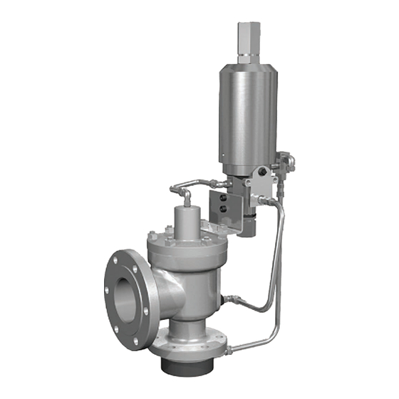
Change in elevation between relief valve and source of Main Valve Base Accessories sensing line may cause set pressure changes. (I.E. Filters) Figure 8: Pilot Operated Safety Relief Valve © 2019 Baker Hughes, a GE company. All Rights Reserved. Consolidated 2900-40 Series POSRV Maintenance Manual | 23... - Page 24 Figures 8 and 9. Figure 8 shows a standard pilot operated relief valve. Figure 9 shows a pilot operated relief valve equipped with a heat exchanger. 24 | BHGE © 2019 Baker Hughes, a GE company. All Rights Reserved.
-
Page 25: Disassembly Of The 2900-40 Posrv
If Main Valve Piston O-Ring or Spring Energize Seal is damaged, then Main Valve Piston may fall out of Cover Plate during disassembly. Remove pipe plug from Cover Plate. © 2019 Baker Hughes, a GE company. All Rights Reserved. Consolidated 2900-40 Series POSRV Maintenance Manual | 25... - Page 26 XIII. Disassembly of the 2900-40 POSRV (Cont.) Figure 10: Metal Seat Valve Disassembly 26 | BHGE © 2019 Baker Hughes, a GE company. All Rights Reserved.
- Page 27 O-Ring Seat Seal O-Ring Retainer Disc Holder Retainer Lockscrew Figure 13: O-Ring Seat (K-T Orifices) Figure 15: Removing the Disc with Drift Pins © 2019 Baker Hughes, a GE company. All Rights Reserved. Consolidated 2900-40 Series POSRV Maintenance Manual | 27...
- Page 28 View From Side Nozzle Pipe Wrench 3 Jaw Chuck Nozzle Base Chuck Stand Figure 16: Loosening the Nozzle from the Base Figure 17: Removing the Nozzle from the Base 28 | BHGE © 2019 Baker Hughes, a GE company. All Rights Reserved.
-
Page 29: Cleaning
Do not “sand blast” internal parts as it can reduce the dimensions of the parts. Follow recommendations for safe handling in the solvent's Material Safety Data Sheet and observe safe practices for any cleaning method © 2019 Baker Hughes, a GE company. All Rights Reserved. Consolidated 2900-40 Series POSRV Maintenance Manual | 29... -
Page 30: Maintenance Instructions
Keep the lap Figure 18a: Metal Seat Nozzle Figure 18b: Soft Seat Nozzle 5° 45° 45° Nozzle Nozzle Bore Bore Figure 18: Main Valve Nozzle Critical Dimensions 30 | BHGE © 2019 Baker Hughes, a GE company. All Rights Reserved. - Page 31 Note 1: Do not remachine threaded areas of the nozzle to reestablish “D” dimension. Once “D” minimum is reached, replacement of nozzle is necessary. © 2019 Baker Hughes, a GE company. All Rights Reserved. Consolidated 2900-40 Series POSRV Maintenance Manual | 31...
-
Page 32: Lapped Nozzle Seat Widths
• Apply 1000 lapping compound (see Table 17 in Lapping Figure 19a: Measuring Magnifier Figure 19b: Magnifier Details Measuring Magni er Nozzle Figure 19: Measuring Magnifier 32 | BHGE © 2019 Baker Hughes, a GE company. All Rights Reserved. - Page 33 Note 2: Not to exceed .070 ± .005" 1.03 6.89 .050 1.27 .060 1.52 (1.78±0.13 mm). 6.96 20.68 .060 1.52 .075 1.91 © 2019 Baker Hughes, a GE company. All Rights Reserved. Consolidated 2900-40 Series POSRV Maintenance Manual | 33...
-
Page 34: Precautions And Hints For Lapping Seats
(Figure 21). The surfaces marked A and B must be running concentric. b. True up the nozzle so that the surfaces marked B and C run true within .001” (0.03 mm) on indicator (Figure 22). 34 | BHGE © 2019 Baker Hughes, a GE company. All Rights Reserved. -
Page 35: Re-Machining The Disc Seat
Do not remachine a Thermodisc or O-Ring Retainer. c. The nozzle is now ready for lapping. d. When the minimum dimension H is reached, discard the nozzle. © 2019 Baker Hughes, a GE company. All Rights Reserved. Consolidated 2900-40 Series POSRV Maintenance Manual | 35... - Page 36 Type 2 .485 12.32 .015 0.38 .610 15.49 .015 0.38 .610 15.49 .015 0.38 .610 15.49 .015 0.38 .822 20.88 .015 0.38 Figure 24: Disc Inspection Areas 36 | BHGE © 2019 Baker Hughes, a GE company. All Rights Reserved.
-
Page 37: Inspection And Part Replacement
If the dimension cannot be measured, replace the 2.315 58.80 2.315 58.80 Thermodisc. 2.315 58.80 2.315 58.80 2.315 58.80 2.315 58.80 O-Ring Seated Disc: The O-Ring Retainer cannot be © 2019 Baker Hughes, a GE company. All Rights Reserved. Consolidated 2900-40 Series POSRV Maintenance Manual | 37... -
Page 38: Disc Holder
O-Rings and seals should be replaced each time the valve is disassembled. Refer to Tables 20 for a list of recommended spare parts and Table 21 for a list of O-Ring repair kits. 38 | BHGE © 2019 Baker Hughes, a GE company. All Rights Reserved. -
Page 39: Reassembly Of 2900-40 Main Valve
± 3 ± 0.3 1/4-28UNF ± 3 ± 0.3 Note 1: DO NOT USE impact wrench on "D" through "K" orifice Nozzles. © 2019 Baker Hughes, a GE company. All Rights Reserved. Consolidated 2900-40 Series POSRV Maintenance Manual | 39... - Page 40 Bellows is present, the weight of the Guide will slightly compress the Bellows. Place the Guide Gasket in the Base. Install disc guide assembly. Use the same lifting tool (see 40 | BHGE © 2019 Baker Hughes, a GE company. All Rights Reserved.
- Page 41 — — — — — — — — — — — — — — — — — — — — — — © 2019 Baker Hughes, a GE company. All Rights Reserved. Consolidated 2900-40 Series POSRV Maintenance Manual | 41...
- Page 42 Make note of the length of the studs. The two longer ones will straddle the vertical line of the inlet sensing port on the Main Base of the pilot valve. Install 42 | BHGE © 2019 Baker Hughes, a GE company. All Rights Reserved.
-
Page 43: Disassembly Of Pilot Valve
1 - Insert Bottom If you are using cleaning solvents, take precautions to 1 - Spring Seal (Insert) protect yourself from potential danger from breathing © 2019 Baker Hughes, a GE company. All Rights Reserved. Consolidated 2900-40 Series POSRV Maintenance Manual | 43... - Page 44 XVII. Disassembly of Pilot Valve (Cont.) 39PV37 Figure 30: 39PV07/37 Disassembly 44 | BHGE © 2019 Baker Hughes, a GE company. All Rights Reserved.
- Page 45 Material Safety Data Sheet and observe safe practices for any cleaning method Figure 31: Lifting Lever Disassembly © 2019 Baker Hughes, a GE company. All Rights Reserved. Consolidated 2900-40 Series POSRV Maintenance Manual | 45...
-
Page 46: Part Inspection Of Pilot Valve
Adjuster Bottom: Galling or excessive wear on the inside diameter that guides the Main Piston. Check for any corrosion or pitting. Also, check for galling of threads. 46 | BHGE © 2019 Baker Hughes, a GE company. All Rights Reserved. -
Page 47: Reassembly Of Pilot Valve
Plunger Adjuster Top Plunger Cylinder Adjuster Bottom Spring Seal Funnel Tube (Main Piston) Figure 32: Funnel Tube Figure 34: Adjuster Top Assembly © 2019 Baker Hughes, a GE company. All Rights Reserved. Consolidated 2900-40 Series POSRV Maintenance Manual | 47... - Page 48 This lubrication is used to hold the O-Ring in place when it is being inserted into Pilot Base. d. Place O-Ring (Insert) into groove. Figure 36: Top Plate (39PV07) 48 | BHGE © 2019 Baker Hughes, a GE company. All Rights Reserved.
- Page 49 Refer to Field Test Connection / Backflow Preventer Option Lever option is installed. (Section XXII.A) for reassembly of Field Test Connection. If pilot has Lifting Lever Option: © 2019 Baker Hughes, a GE company. All Rights Reserved. Consolidated 2900-40 Series POSRV Maintenance Manual | 49...
-
Page 50: Setting And Testing
The vent port of the pilot valve is vented to atmosphere in standard configuration. Final standard configuration for a 39PV07 or 39PV37 without any options is shown in Figure 38. 50 | BHGE © 2019 Baker Hughes, a GE company. All Rights Reserved. -
Page 51: With Sensing Ring Option
If no bubbles are present, then leakage is either coming from the c. Drop system to 90% of set pressure between cycles. © 2019 Baker Hughes, a GE company. All Rights Reserved. Consolidated 2900-40 Series POSRV Maintenance Manual | 51... - Page 52 Pressure may be applied directly to the valve dome or via the pilot valve. Leakage may be detected by application of soap solution, or equivalent, at points of possible leakage. Pressure 52 | BHGE © 2019 Baker Hughes, a GE company. All Rights Reserved.
-
Page 53: Field Testing Of Posrv Assembly
The system shown in Figure 41 is available for remote or local testing. © 2019 Baker Hughes, a GE company. All Rights Reserved. Consolidated 2900-40 Series POSRV Maintenance Manual | 53... -
Page 54: Troubleshooting
Discharging into a closed container or Install Backflow Preventer. not enough capacity in the discharge system. 54 | BHGE © 2019 Baker Hughes, a GE company. All Rights Reserved. -
Page 55: 2900-40 Series Posrv Options
2. Cleaning agents used shall be such that effective cleaning Figure 43: Backflow Preventer Option is assured without injuring the surface finishes or material properties of the part. © 2019 Baker Hughes, a GE company. All Rights Reserved. Consolidated 2900-40 Series POSRV Maintenance Manual | 55... -
Page 56: Dual Pilots
56 | BHGE © 2019 Baker Hughes, a GE company. All Rights Reserved. -
Page 57: Sensing Line Filter (Standard)
Note: See page 74 for replacement filter parts information. © 2019 Baker Hughes, a GE company. All Rights Reserved. Consolidated 2900-40 Series POSRV Maintenance Manual | 57... -
Page 58: Gag
POSRV shall be piped so that the media enters the heat exchanger first to condition the media’s temperature. Option(s) such as line filter, canister filter, 5-way 58 | BHGE © 2019 Baker Hughes, a GE company. All Rights Reserved. -
Page 59: Lifting Lever
I. Manual, Electrical, or Pneumatic Blowdown Valve Figure 51: Manual Blowdown Valve Figure 52: Electrical Blowdown Valve © 2019 Baker Hughes, a GE company. All Rights Reserved. Consolidated 2900-40 Series POSRV Maintenance Manual | 59... -
Page 60: Pilot Valve Tester
Figure 53: Pilot Valve Tester Figure 54: Pressure Differential Switch (Shown with optional 5-way manifold valve and sensing ring) 60 | BHGE © 2019 Baker Hughes, a GE company. All Rights Reserved. -
Page 61: Pressure Spike Snubber
(for tubing size and maximum length, consult factory for recommendations). © 2019 Baker Hughes, a GE company. All Rights Reserved. Consolidated 2900-40 Series POSRV Maintenance Manual | 61... -
Page 62: Maintenance Tools And Supplies
ø .145” ± .002” 1.000” ø .375” ± .002” (3.68 ± 0.05 (25.40 mm) (9.53 ± 0.05 1.063” (26.99 mm) Figure 57: Adjuster Top Seal Insertion Tool 62 | BHGE © 2019 Baker Hughes, a GE company. All Rights Reserved. -
Page 63: Insert Installation Tool
.125” (3.18 mm) (TYP) ITEM 2 ITEM 3 .750” (19.05mm) ø.250” 2.9375” (6.35mm) (74.61mm) .313” (794mm) SQ Figure 58: Insert Installation Tool © 2019 Baker Hughes, a GE company. All Rights Reserved. Consolidated 2900-40 Series POSRV Maintenance Manual | 63... -
Page 64: Lapping Tools
1672813 Note 1: Ring Laps: One set of three (3) ring laps is recommended for each orifice to assure ample flat laps are available at all times. 64 | BHGE © 2019 Baker Hughes, a GE company. All Rights Reserved. -
Page 65: Disc Holder And Guide Removal And Assembly Tool
M THREADS Ø L HOLE Ø M HOLE DET. 3 DET. 5 Figure 60: Disc Holder and Guide Removal and Assembly Tool © 2019 Baker Hughes, a GE company. All Rights Reserved. Consolidated 2900-40 Series POSRV Maintenance Manual | 65... - Page 66 7) Use a Standard Nut – .375" (9.53 mm) - 16 thd. 8) Use a Standard Nut – .625" (15.88 mm) - 11 thd. Additional: Use an appropriate sized O-Ring in groove “I”, to hold the parts together. 66 | BHGE © 2019 Baker Hughes, a GE company. All Rights Reserved.
-
Page 67: Replacement Parts Planning
How to verify Materials of O-Rings and Seals: Kit coding indicates O-Ring and seals material. Examples: M0RK-70T006 PSGK - 32E019 Teflon ® Ethylene/Propylene © 2019 Baker Hughes, a GE company. All Rights Reserved. Consolidated 2900-40 Series POSRV Maintenance Manual | 67... -
Page 68: Positive Identification Of Main Valve And Pilot Valve Combinations
BHGE guarantees the parts • Consolidated valve products have been in use since 1879 • BHGE has worldwide service • BHGE has fast response availability for parts 68 | BHGE © 2019 Baker Hughes, a GE company. All Rights Reserved. -
Page 69: Recommended Spare Parts
Notes 1: A combination of Class I and II parts will satisfy maintenance requirements 85% of the time. 2: Depending on service, either an O-Ring or Spring Energized Teflon ® Seal is required. © 2019 Baker Hughes, a GE company. All Rights Reserved. Consolidated 2900-40 Series POSRV Maintenance Manual | 69... - Page 70 M0RK29004T006 2912,14,16,24,26 M0RK29018T006 2905,06,10,12,20,22,24 M0RK29005T006 2914,16 M0RK29023T006 2926,28 M0RK29026T006 2905,06,10,12,20,22 M0RK29006T006 2914,16,24,26 M0RK29024T006 2905,06,10,12,14,20,22,24 M0RK29007T006 2905,06,10,12,14,20,22,24 M0RK29008T006 2905,06,10,20 M0RK29009T006 2912,14 M0RK29019T006 2905,06,10,12,20,22 M0RK29010T006 2905,06,10,12,20,22 M0RK29011T006 2905,06,10,12,20,22 M0RK29012T006 70 | BHGE © 2019 Baker Hughes, a GE company. All Rights Reserved.
- Page 71 2914,16 M0RK29023E002 2926,28 M0RK29026E002 2905,06,10,12,20,22 M0RK29006E002 2914,16,24,26 M0RK29024E002 2905,06,10,12,14,20,22,24 M0RK29007E002 2905,06,10,12,14,20,22,24 M0RK29008E002 2905,06,10,20 M0RK29009E002 2912,14 M0RK29019E002 2905,06,10,12,20,22 M0RK29010E002 2905,06,10,12,20,22 M0RK29011E002 2905,06,10,12,20,22 M0RK29012E002 © 2019 Baker Hughes, a GE company. All Rights Reserved. Consolidated 2900-40 Series POSRV Maintenance Manual | 71...
- Page 72 M0RK29004E019 2912,14,16,24,26 M0RK29018E019 2905,06,10,12,20,22,24 M0RK29005E019 2914,16 M0RK29023E019 2926,28 M0RK29026E019 2905,06,10,12,20,22 M0RK29006E019 2914,16,24,26 M0RK29024E019 2905,06,10,12,14,20,22,24 M0RK29007E019 2905,06,10,12,14,20,22,24 M0RK29008E019 2905,06,10,20 M0RK29009E019 2912,14 M0RK29019E019 2905,06,10,12,20,22 M0RK29010E019 2905,06,10,12,20,22 M0RK29011E019 2905,06,10,12,20,22 M0RK29012E019 72 | BHGE © 2019 Baker Hughes, a GE company. All Rights Reserved.
- Page 73 Note 1: Field Test Connector Consist of one of the Select Shuttle Valve assemblies shown above. SP561-Q replaced by 6000609, SP561-R replaced by 6000608, SP468-G replaced by 6000622 © 2019 Baker Hughes, a GE company. All Rights Reserved. Consolidated 2900-40 Series POSRV Maintenance Manual | 73...
- Page 74 Note: The sensing tube filter element cannot be cleaned and must be replaced when clogged. Table 28: High Capacity Filter Replacement Parts No. Required Description Part No. Per Valve Filter Element 6027301 O-Rings 31006131 74 | BHGE © 2019 Baker Hughes, a GE company. All Rights Reserved.
-
Page 75: Manufacture's Field Service, Repair, And Training Programs
The Repair Department, in conjunction with the manufacturing facilities, is equipped to perform specialized repairs and product modifications, e.g. butt-weld, bushing replacements, code welding, pilot replacement, etc. © 2019 Baker Hughes, a GE company. All Rights Reserved. Consolidated 2900-40 Series POSRV Maintenance Manual | 75... -
Page 76: End Users Notes
Notes: 76 | BHGE © 2019 Baker Hughes, a GE company. All Rights Reserved. - Page 77 Notes: © 2019 Baker Hughes, a GE company. All Rights Reserved. Consolidated 2900-40 Series POSRV Maintenance Manual | 77...
- Page 78 Notes: 78 | BHGE © 2019 Baker Hughes, a GE company. All Rights Reserved.
- Page 79 Notes: © 2019 Baker Hughes, a GE company. All Rights Reserved. Consolidated 2900-40 Series POSRV Maintenance Manual | 79...
- Page 80 The BHGE logo is a trademark of Baker Hughes, a GE company LLC. GE and the GE monogram are trademarks of the General Electric Company used under trademark license.
Need help?
Do you have a question about the Baker Hughes 2900-40 Series and is the answer not in the manual?
Questions and answers