
Related Manuals for Hydac MCS1 T001 Series


Summary of Contents for Hydac MCS1 T001 Series
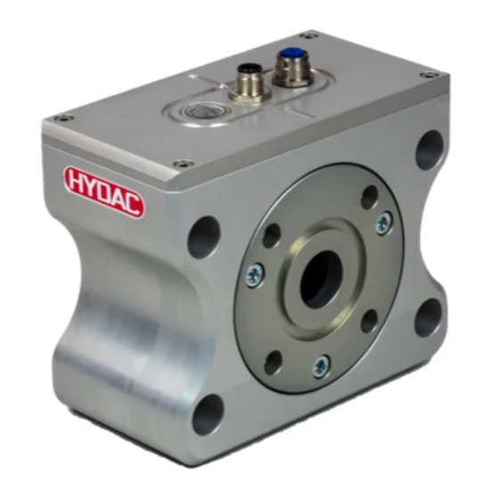
- Page 1 MCS1xxx /-T001 Metallic Contamination Sensor Operation and Installation Guide English (translation of original instructions) Documentation no.: 4686072 Valid from hardware index D and firmware version C09.30 up...
-
Page 2: Imprint
Court of Registration: Saarbrücken, HRB 17216 Executive directors: Mathias Dieter, Dipl.Kfm. Wolfgang Haering Documentation Representative Mr. Günter Harge c/o HYDAC International GmbH, Industriegebiet, 66280 Sulzbach / Saar Telephone: +49 6897 509 1511 Fax: +49 6897 509 1394 E-mail: guenter.harge@hydac.com © HYDAC FILTER SYSTEMS GMBH All rights reserved. -
Page 3: Table Of Contents
Content Content Imprint ......................2 Documentation Representative ..............2 Content ......................3 Preface ......................6 Technical Support ................6 Modifications to the Product ............6 Warranty ..................6 Using the documentation ..............7 Safety information ..................8 Warning signs used ................ 8 Others symbols used .............. - Page 4 Content Dimensions MCS 15xx-3 .............. 27 Dimensions MCS 15xx with flange adapter set (optional accessories) ................. 27 Mechanical installation/assembly ............. 28 Connecting MCS 13xx / 14xx via flange adapter set ....29 Fastening sensor to underside ..............30 Fastening MCS 13xx / MCS 14xx ..........31 Fastening MCS 15xx ..............
- Page 5 Content PowerUp Menu .................... 50 MODE - select operating mode ............ 50 S.TIME - Set storing interval ............50 SEL.COM - Set protocol ............... 50 ADRESS – Set bus address ............50 DFAULT - Reset to factory setting ..........50 CANCEL - cancel without saving ..........
-
Page 6: Preface
Please notify us immediately of any modifications made to the product whether by you or a third party. Warranty For the warranty provided by us, please refer to the terms of delivery of HYDAC FILTER SYSTEMS GMBH. You will find these under www.hydac.com -> General terms and conditions. -
Page 7: Using The Documentation
Preface Using the documentation Note that the method described for locating specific information does not release you from your responsibility of carefully reading these instructions prior to starting the unit up for the first time and at regular intervals in the future. What do I want to know? I determine which topic I am looking for. -
Page 8: Safety Information
Safety information Safety information The device was built according to the statutory provisions valid at the time of delivery and satisfies current safety requirements. Any residual hazards are indicated by general safety information and instructions and are described in the operating instructions. Observe all safety and warning instructions attached to the unit. -
Page 9: Signal Words And Their Meaning In The General Safety Information
Safety information Signal words and their meaning in the general safety information In these instructions you will find the following signal words: DANGER DANGER – The signal word indicates a hazardous situation with a high level of risk, which, if not avoided, will result lethal or serious injury. WARNING WARNING –... -
Page 10: Intended Use
Safety information Intended Use Use the sensor only for the application described below. The MetallicContamination Sensor MCS is used for the constant monitoring of particulate contamination in hydraulic and lubrication systems. Proper/designated use of the product extends to the following: •... -
Page 11: Improper Use Or Use Deviating From Intended Use
Safety information Improper use or use deviating from intended use Any other use or extended use shall not be considered intended use. HYDAC FILTER SYSTEMS GMBH will assume no liability for any damage resulting from such use. This risk is borne solely by the owner. - Page 12 Safety information • Product-specific Operation Specialist personnel knowledge Operations control • Knowledge about how to handle operating media. • Knowledge about reuse Disposal Specialist personnel Page 12 / 68 MCS1xxx /-T001 en(us) BeWa MCS1xxx-T001 4686072 en-us 2022-06-15.docx 2022-06-15...
-
Page 13: Transporting The Sensor
Transporting the sensor Transporting the sensor Transport the sensor upright or flat, and in the included packaging if possible. Make sure the connection plug will not be subjected to any mechanical strain or impact. NOTICE Unsafe transport The connection plug will be damaged ►... -
Page 14: Decoding The Model Code Label
Decoding the model code label Decoding the model code label For identification details of the MetallicContamination Sensor, see the type label. This is located on the top of the unit and contains the exact product description and the serial number. Definition Description Model... -
Page 15: Checking The Scope Of Delivery
Checking the scope of delivery Checking the scope of delivery The scope of delivery for the available sizes varies. Below is the scope of delivery for each size. Scope of delivery for MCS 13xx The MetallicContamination Sensor MCS 13xx comes packed and factory- assembled. -
Page 16: Scope Of Delivery For Mcs 14Xx
Checking the scope of delivery Scope of delivery for MCS 14xx The MetallicContamination Sensor MCS 14xx comes packed and factory- assembled. Before commissioning the sensor, please check no items are missing from the package. The following items are supplied: Qty. Description MetallicContamination Sensor, MCS 14xx O-ring (25 x 3.53 NBR 70 Shore) -
Page 17: Scope Of Delivery For Mcs 15Xx
Checking the scope of delivery Scope of delivery for MCS 15xx The MetallicContamination Sensor MCS 15xx comes packed and factory- assembled. Before commissioning the sensor, please check no items are missing from the package. The following items are supplied: Qty. Description MetallicContamination Sensor, MCS 15xx o-ring (47.22 x 3.53 NBR 70 Shore) -
Page 18: Scope Of Delivery For Mcs 15Xx-3
Checking the scope of delivery Scope of delivery for MCS 15xx-3 The MetallicContamination Sensor MCS 15xx-3 comes packed and factory- assembled. Before commissioning the sensor, please check no items are missing from the package. The following items are supplied: Qty. Description MetallicContamination Sensor, MCS 15xx-3 O-ring (32.92 x 3.53 NBR 70 Shore) -
Page 19: Sensor Features
Sensor features Sensor features The MetallicContamination Sensor MCS is a stationary sensor for continuous monitoring of contamination of fluids – especially lubrication fluids – with metallic particles. With appropriate system knowledge of the monitored system, damage resulting in detectable metallic particles can be discovered early. The MCS uses digital signal processing to distinguish between ferromagnetic (Fe) and non-ferromagnetic (nFe) particles. -
Page 20: Sensor Dimensions
Sensor dimensions Sensor dimensions The dimensions for the available sizes vary. The dimensions for each size can be found below. Dimensions Flange image SAE 1/2" All dimensions in mm. Page 20 / 68 MCS1xxx /-T001 en(us) BeWa MCS1xxx-T001 4686072 en-us 2022-06-15.docx 2022-06-15... -
Page 21: Dimensions For Mcs 13Xx With Ethernet Module
Sensor dimensions Dimensions for MCS 13xx with Ethernet module Flange image SAE 1/2" All dimensions in mm. Page 21 / 68 MCS1xxx /-T001 en(us) BeWa MCS1xxx-T001 4686072 en-us 2022-06-15.docx 2022-06-15... -
Page 22: Dimensions Mcs 13Xx With Flange Adapter Set (Optional Accessories)
Sensor dimensions Dimensions MCS 13xx with flange adapter set (optional accessories) All dimensions in mm. Page 22 / 68 MCS1xxx /-T001 en(us) BeWa MCS1xxx-T001 4686072 en-us 2022-06-15.docx 2022-06-15... -
Page 23: Dimensions
Sensor dimensions Dimensions Flange image SAE 3/4" All dimensions in mm. Page 23 / 68 MCS1xxx /-T001 en(us) BeWa MCS1xxx-T001 4686072 en-us 2022-06-15.docx 2022-06-15... -
Page 24: Dimensions For Mcs 14Xx With Ethernet
Sensor dimensions Dimensions for MCS 14xx with Ethernet Flange image SAE 3/4" All dimensions in mm. Page 24 / 68 MCS1xxx /-T001 en(us) BeWa MCS1xxx-T001 4686072 en-us 2022-06-15.docx 2022-06-15... -
Page 25: Dimensions Mcs 14Xx With Flange Adapter Set (Optional Accessories)
Sensor dimensions Dimensions MCS 14xx with flange adapter set (optional accessories) All dimensions in mm. Dimensions Flange image SAE 4" All dimensions in mm. Page 25 / 68 MCS1xxx /-T001 en(us) BeWa MCS1xxx-T001 4686072 en-us 2022-06-15.docx 2022-06-15... -
Page 26: Dimensions For Mcs 15Xx With Ethernet
Sensor dimensions Dimensions for MCS 15xx with Ethernet Flange image SAE 3/4" All dimensions in mm. Page 26 / 68 MCS1xxx /-T001 en(us) BeWa MCS1xxx-T001 4686072 en-us 2022-06-15.docx 2022-06-15... -
Page 27: Dimensions Mcs 15Xx-3
Sensor dimensions Dimensions MCS 15xx-3 Flange connection, SAE 1" according to ISO 6162-1. All dimensions in mm. Dimensions MCS 15xx with flange adapter set (optional accessories) All dimensions in mm. Page 27 / 68 MCS1xxx /-T001 en(us) BeWa MCS1xxx-T001 4686072 en-us 2022-06-15.docx 2022-06-15... -
Page 28: Mechanical Installation/Assembly
Mechanical installation/assembly Mechanical installation/assembly During installation, always observe the direction of flow through the sensor. The direction of flow is indicated by an arrow on the housing. When selecting the installation site, take ambient factors like the temperature, dust, water, etc., into account. The sensor is designed for IP67 according to DIN 40050 / EN 60529 / IEC 529 / VDE 0470. -
Page 29: Connecting Mcs 13Xx / 14Xx Via Flange Adapter Set
Mechanical installation/assembly Connecting MCS 13xx / 14xx via flange adapter set A flange adapter set is available as an accessory. For the article no., refer to Chapter "Spare parts and accessories" on page 56. This flange adapter set makes it possible to connect the MCS directly to pipes or hoses with a G1/2"... -
Page 30: Fastening Sensor To Underside
Fastening sensor to underside Fastening sensor to underside The sensors have four fixing holes on the underside. Use these to secure the MCS. Page 30 / 68 MCS1xxx /-T001 en(us) BeWa MCS1xxx-T001 4686072 en-us 2022-06-15.docx 2022-06-15... -
Page 31: Fastening Mcs 13Xx / Mcs 14Xx
Fastening sensor to underside Fastening MCS 13xx / MCS 14xx Below you can see the drilling template for fastening the MCS 13xx/MCS 14xx. (All dimensions in mm) Fastening MCS 15xx Below you can see the drilling template for fastening the MCS 15xx. (All dimensions in mm) Page 31 / 68 MCS1xxx /-T001... -
Page 32: Fastening Mcs 15Xx Using Angle Fastening Set
3477243. Connecting MCS 15xx using pipe adapter set A pipe adapter set is available as an accessory. HYDAC article no. 3435426. This pipe adapter set makes it possible to connect the MCS directly to two pipes or hoses via the thread 42L per ISO8431-1. -
Page 33: Connecting Mcs 15Xx Using Flange Adapter Plate (Accessory)
Fastening sensor to underside Connecting MCS 15xx using flange adapter plate (accessory) A flange adapter set is available as an accessory. HYDAC article no. 3442518. The SAE4"-SAE1½" (1) flange adapter set can be used to mount the MCS between the filter unit and the pump. The flange adapter plate offers three ¼"... -
Page 34: Mcs 15Xx Via Sae 4" Per Iso 6162-1 (4Xm16)
Fastening sensor to underside MCS 15xx via SAE 4" per ISO 6162-1 (4xM16) Install the MCS with four screws (M16) to a component/unit. The drilling template corresponds to the SAE 4" per ISO 6162-1. Example: installing the MCS on an NF filter Page 34 / 68 MCS1xxx /-T001 en(us) -
Page 35: Hydraulic Installation Of Sensor
Hydraulic installation of sensor Hydraulic installation of sensor During installation, note the direction of flow through the MCS. The direction of flow is indicated by an arrow on the housing. NOTICE Exceeding the permissible operating pressure The sensor will be destroyed ►... - Page 36 Hydraulic installation of sensor Q l/min Q l/min p ∆ The diagram shows the resulting differential pressure mbar as a function of the flow rate Q l/min at different viscosities. Page 36 / 68 MCS1xxx /-T001 en(us) BeWa MCS1xxx-T001 4686072 en-us 2022-06-15.docx 2022-06-15...
-
Page 37: Electrical Connection Of Sensor
Description Meaning Power supply 18 … 30 V DC Switching output 2 (binary voltage GND/Vs) Reference point for power supply Reference point for power supply HYDAC Sensor Interface RS485 + Bus Interface RS485 - Bus Interface Out 1 Switching output 1 (binary voltage GND/Vs) There is contact between the plug housing and the housing. -
Page 38: Connection Cable - Assignment / Color Coding
Our accessories list includes connection cables of various lengths with one connection plug (8-pole, M12x1, according to DIN VDE 0627) and an open end. The color coding of the HYDAC accessory cable ZBE42-xx is listed in the table below: (All dimensions in mm) -
Page 39: Using The Switching Outputs
Using the switching outputs Using the switching outputs The two switching outputs delivery pulses that can be counted or utilized in a superordinate controller. The function and logic of the signal outputs is parameterizable. You can select between "active low" and "active high" (factory setting). Details on setting the switching outputs can be found starting on page 52. -
Page 40: Example: Operation - 1 Particle Detected = Logical "Active
Using the switching outputs You can set the duration of the particle signal between 5 - 200 Ms. This value is factory set to 7 ms. The signal gives no indication of the shape and size of the particles. The duration of alarm signal is set to 30 seconds Note that after the sensor has been switched on or after voltage has returned, a start-up phase of ≈... -
Page 41: Switching Logic "Active High" (Default Settings)
Using the switching outputs Switching logic "active high" (Default settings) When particles are detected, both switching outputs emit an impulse with an increasing edge. You can set the duration of the signal Δt between 5 and 200 ms. This value is factory set to 7 ms. The signal gives no indication of the shape and size of the particles. -
Page 42: Example: Operation - 1 Particle Detected = Logical "Active
Using the switching outputs Example: Operation - 1 particle detected = logical "active" Example: Operation - no particle detected = logical "not active" Page 42 / 68 MCS1xxx /-T001 en(us) BeWa MCS1xxx-T001 4686072 en-us 2022-06-15.docx 2022-06-15... -
Page 43: Example: Operation - Several Particles Detected = Logical "Active
Using the switching outputs Example: Operation - several particles detected = logical "active" Switching logic „Device Ready“ The signal indicating that the MCS is ready for use can be emitted on the switching output S2. Note that after the sensor has been switched on and after voltage has returned after an interruption, a start-up phase of ≈... -
Page 44: Parameterizing Sensor/Reading Measured Values
Parameterizing sensor/reading measured values Parameterizing sensor/reading measured values Connecting MCS 1000 to SMU 1200 The MCS 1000 can be connected to the HYDAC SensorMonitoring Unit SMU 1200. The SMU 1200 makes it possible to: • set parameters • save the MCS measurement data with a time stamp •... -
Page 45: Connecting Mcs To Csi-D-5 (Condition Sensor Interface)
Connecting MCS to CSI-D-5 (Condition Sensor Interface) The CSI-D-5 kit can be used to parameterize the MCS using a PC and to read off online and stored measurement data. Connect the CSI-D-5 kit, HYDAC article no. 3249563, in accordance with the following connection diagram: CSI-D-5 Kit... -
Page 46: Connecting Mcs To Hmg 3000
Parameterizing sensor/reading measured values Connecting MCS to HMG 3000 You can use the HMG 3000 to set the parameters of the MCS. Connect the HMG 3000 to the MCS in accordance with the following connection diagram. You can find more details in the HMG 3000 operating instructions. Page 46 / 68 MCS1xxx /-T001 en(us) -
Page 47: Evaluating Measurement Results
Evaluating measurement results Evaluating measurement results The counter readings of the MCS are not comparable with particle concentrations as these are known from optical particle counters per ISO 4406. If the counter reading stays the same, this does not mean that a constant particle concentration is present, but rather the no further particles have been detected. -
Page 48: Menu Structure
Menu structure Menu structure This chapter gives you an overview of the menu structure of the PowerUP and Measuring menus. Overview - PowerUP Menu PowerUP menu MODE S.TIME SEL.COM ADRESS DEFAULT CANCEL SAVE Page 48 / 68 MCS1xxx /-T001 en(us) BeWa MCS1xxx-T001 4686072 en-us 2022-06-15.docx 2022-06-15... -
Page 49: Overview - Measuring Menu
Menu structure Overview - Measuring Menu Measuring menu DSPLAY FE A FE B FE C NFE D NFE E NFE F CYC A CYC B CYC C CYC D CYC E CYC F STATUS TEMP C TEMP F SWT.OUT FE.NFE ALL.RDY ALARM SWT.LOG... -
Page 50: Powerup Menu
PowerUp Menu PowerUp Menu MODE - select operating mode Function: Adjustment not possible Parameter: None Factory setting: M2 (Measure and switch) S.TIME - Set storing interval Function: After the time interval set, the total number of particles is written to the memory of the MCS. The number of particles within the time intervals can be seen from the parameter DSPLAY - CYC. -
Page 51: Measuring Menu
Measuring menu Measuring menu DSPLAY - Show measured variable Function: Select the measured variable that is displayed after switching the unit on and after voltage has returned. The measured variables FE A to NFE F show a summation of the particles in the corresponding category. -
Page 52: Swt.out - Set The Switching Output
Measuring menu STATUS: Status byte (00 at status = O.K.) Field strength of the field coil in the MCS TEMP C: Medium temperature in °C (indirect measurement via sensor in the spool) TEMP F: Medium temperature in °F (indirect measurement via sensor in the spool) Factory setting: FE A The value of 1000 µm is shown on the display as 1k. -
Page 53: Alarm - Setting Limit Values
Error analysis / remedy Parameter: TYPE FE = switching output 1 NFE = switching output 2 Number of pulses START Start of function test Factory setting: TYPE ALARM – Setting limit values Function: Set limit values. The signal is active for 30 seconds after exceeding a limit value. -
Page 54: Performing Maintenance
Performing Maintenance Pull out the plug. Check the supply voltage on the cable plug. In order to activate switching output, bridge pins 2 and 3 as well as 8 and 4. Check the supply voltage (Vs) activated in this way at the cable end on the output side. -
Page 55: Decommissioning The Sensor
Decommissioning the sensor Decommissioning the sensor To decommission the unit, proceed as follows: Remove the electric plug. Depressurize the unit. Remove the connected hoses/piping from the sensor. Remove the sensor. Disposing of sensor/packaging material Dispose of the packaging material in an environmentally friendly manner. After removing the sensor and separating its various materials, dispose of it in an environmentally friendly manner. -
Page 56: Spare Parts And Accessories
Spare parts and accessories Spare parts and accessories The following spare parts and accessories are available for the sensor. Description Part no. MCS 14xx Flange adapter set SAE ¾“ - G 1/2““, consisting of: 1x SAE flange 1x O-ring (NBR) 4x cheese-head screw 3588249 MCS 15xx Pipe adapter set 42L, consisting of:... - Page 57 Spare parts and accessories Description Part no. MCS 15xxMCS15xx angle plate set, consisting of: 1x angle plate 4x cheese-head screw 8x washer 4x snap ring 4x nut 3477243 O-ring (18.7 x 3.53 NBR 70 Shore) 3112091 O-ring (18.7 x 3.53 FPM low-temperature 70 Shore) 6140581 O-ring (25 x 3.53 NBR 70 Shore) 601905...
-
Page 58: Channel Default Settings
Channel default settings Description Part no. Extension cable 5 m, ZBE 43-05 Socket plug (female) 8-pole, M12x1 / 3281240 Socket plug (male) 8-pole, M12x1 Socket plug (female) with screw clamp, ZBE 44 3281243 8-pole, M12x1 Connection cable – Ethernet, ZBE 45-05 Length 5 m, Patch 3346100 coupling socket 4-pin, M12x1 /... -
Page 59: Customer Service / Service
Customer Service / Service Customer Service / Service Use the following shipping address for repairs: HYDAC SERVICE GMBH Friedrichsthaler Straße 15a, Plant 13 66540 Neunkirchen-Heinitz Germany Telephone: +49 6897 509 01 Fax: +49 6897 509 324 E-mail: service@hydac.com Page 59 / 68... -
Page 60: Technical Data
Technical Data Technical Data Hydraulic data MCS 13xx MCS 14xx MCS 15xx Permissible flow rate 0.4 … 8 l/min 2 … 40 l/min 10 … 200 l/mi Maximum operating 20 bar / 20 bar / 20 bar / pressure 290 psi 290 psi 290 psi Permissible fluid... -
Page 61: Detection Limits
Technical Data Electrical data 2 switching outputs, binary 1 x Ferromagnetic (Fe) particle (gauge GND, VS) 1 x Non-ferromagnetic (nFe) particle 1 x Particle (Fe + nFe) 1 x Device Ready signal 1 x Alarm 1 x Device Ready signal ≤... -
Page 62: Model Code
Model Code Model Code 0 - 5 - 0 / 000 Product = MetallicContamination Sensor Series = 1000 Contamination / sensor cross-section = Particle >70 µm / 1/4" = Particle >100 µm / 1/2" = Particle >200 µm / 1“ Signal technology 2x switching outputs /RS485 (HSI protocol) -
Page 63: Ec Declaration Of Conformity
EC declaration of conformity EC declaration of conformity The CE declaration of conformity can be found in the product's scope of delivery. Glossary Ferromagnetic (Fe) A "ferromagnetic" material is one that turns into a magnet through the influence of an external magnetic field. Examples are iron, cobalt, and nickel, which have this property at room temperature. -
Page 64: Index
Index Index accident prevention Imprint Adjustment INLET ambient temperature 10, 60 installation 11, 28, 33, 35 Assignment installing Auxiliary personnel Interface 37, 38, 45, 58 IP 60 ISO 27, 34, 47, 62 calibrating care 2, 6 Connection 38, 58 Maintenance 11, 54 Connection cable 38, 58... - Page 65 Index TCP 62 USB 44 TCP/IP TEMP 49, 52 Transport 11, 13 Troubleshooting Weight Page 65 / 68 MCS1xxx /-T001 en(us) BeWa MCS1xxx-T001 4686072 en-us 2022-06-15.docx 2022-06-15...
- Page 66 Index Page 66 / 68 MCS1xxx /-T001 en(us) BeWa MCS1xxx-T001 4686072 en-us 2022-06-15.docx 2022-06-15...
- Page 67 Index Page 67 / 68 MCS1xxx /-T001 en(us) BeWa MCS1xxx-T001 4686072 en-us 2022-06-15.docx 2022-06-15...
- Page 68 HYDAC FILTER SYSTEMS GMBH Industriegebiet Postfach 1251 66280 Sulzbach / Saar 66273 Sulzbach / Saar Germany Germany Tel: .+49 6897 509 01 Central Fax: +49 6897 509 9046 Technical Department Fax: +49 6897 509 577 Sales Internet: www.hydac.com E-Mail: filtersystems@hydac.com...
Need help?
Do you have a question about the MCS1 T001 Series and is the answer not in the manual?
Questions and answers