Advertisement
INSTALLATION INSTRUCTIONS FOR PART INSTGMOS-05
GM non-amplified OnStar Class II Data
Bus Interface 2000-2004
• Provides accessory (12-volt 10-amp)
• Retains R.A.P. (Retained Accessory Power)
• Used in non-amplified systems or when replacing amplified systems
• Retains chimes
• Provides NAV outputs (Parking Brake, Reverse, Mute, V.S.S.)
• ASWC harness included (ASWC not included)
• Retains OnStar/OE Bluetooth
• Adjustable volume for chimes and OnStar
• High level speaker input
• USB updatable
• Retains balance and fade
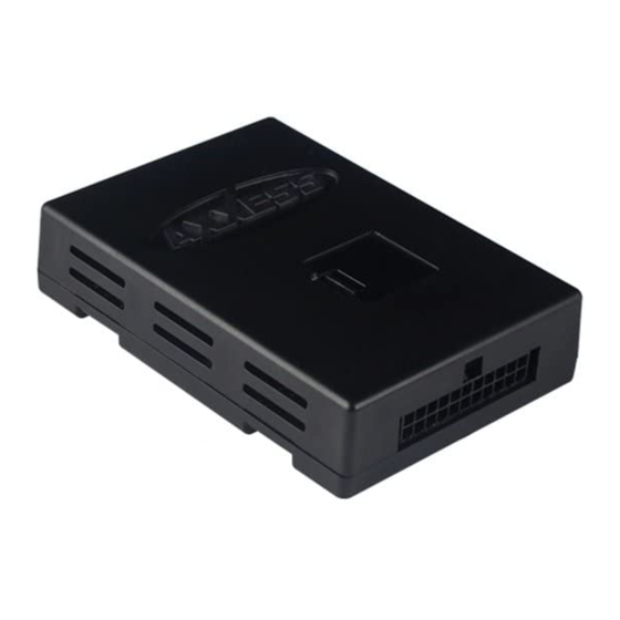
GMOS-05 interface • 16-pin harness with stripped leads
14-pin harness to 32-pin GM harness with stripped leads
Cutting Tool • Crimping Tool • Tape • Connectors (example: butt-connectors, bell caps, etc.
1-800-221-0932
© COPYRIGHT 2004-2011 METRA ELECTRONICS CORPORATION
GMOS-05
See inside front cover
KIT FEATURES
INTERFACE COMPONENTS
TOOLS REQUIRED
METRA. THE WORLD'S BEST KITS.™
metraonline.com
Advertisement
Table of Contents

Summary of Contents for Axxess GMOS-05
- Page 1 • USB updatable • Retains balance and fade INTERFACE COMPONENTS GMOS-05 interface • 16-pin harness with stripped leads 14-pin harness to 32-pin GM harness with stripped leads TOOLS REQUIRED Cutting Tool • Crimping Tool • Tape • Connectors (example: butt-connectors, bell caps, etc.
- Page 2 GMOS-05 Applications (Note: This interface will also work in vehicles listed below that are not equipped with OnStar) BUICK PONTIAC Le Sabre 2000-2004 Bonneville 2000-2004 00-2005 OLDSMOBILE Aurora 2001-2003 Caution Metra recommends disconnecting the negative battery terminal before beginning any installation.
- Page 3 • Connect the Blue/Pink wire to the VSS or speed sense wire of the aftermarket navigation radio. • Connect the Green/Purple wire to the reverse wire of the aftermarket navigation radio. • Plug the 16 pin harness into the GMOS-05...
- Page 4 • Connect the Purple wire to the radio’s right rear positive speaker output. • Connect the Purple/Black wire to the radio’s right rear negative speaker output. • Plug the 14-pin harness into the GMOS-05 • The Black/Yellow wire is for the OnStar volume adjustment. This will be discussed in the OnStar Level Adjustment section of this instruction.
- Page 5 GMOS-05 Testing the GMOS-05 1) Turn the ignition on if not already, and then turn the radio on to verify that the radio works. Check balance and fader controls for proper operation. 2) Push the OnStar button (if equipped) to verify OnStar is working. The radio will shut off or mute, depending if the Brown wire on the 16-pin harness is connected, and OnStar will be heard through the front speakers.
- Page 6 GMOS-05 Aftermarket radio and amplifier wiring...
- Page 7 Notes...
- Page 8 INSTALLATION INSTRUCTIONS FOR PART INSTGMOS-05 IMPORTANT WARNING This product includes instructions for installation which must be carefully followed. The instructions are worded in such a manner to assume that the installer is capable of completing these type of electronic installations. If you are unclear as to what you are instructed to do or believe that you do not understand the instructions so as to properly and safely complete the installation you should consult a technician who does have this knowledge and understanding.


Need help?
Do you have a question about the GMOS-05 and is the answer not in the manual?
Questions and answers