Nilfisk-ALTO Scrubtec R 6-71C 28C Service Manual
Clarke focus ii rider 28 d base; clarke focus ii rider 34 d obc base; clarke focus ii rider 34 d base; clarke focus ii rider 28 b base; clarke focus ii rider 28 b obc base; clarke focus ii rider 28 d obc base; 56114000; 56114001; 56114002; 56114003; 56114
Table of Contents
Advertisement
Quick Links
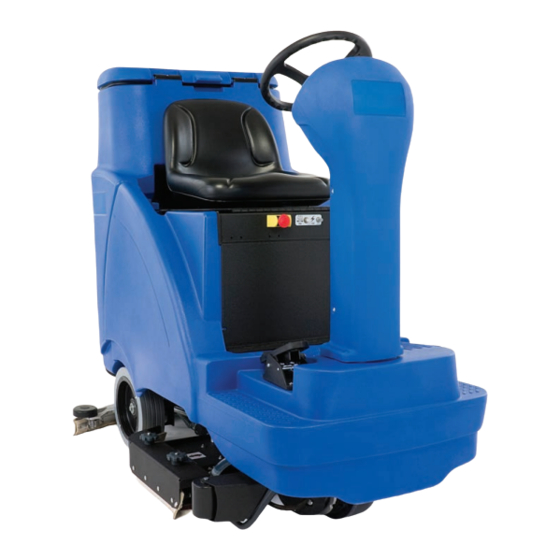
Clarke Focus II Rider Autoscrubber
Nilfisk-Alto Scrubtec R6 Rider Autoscrubber
Service Manual
Clarke
model numbers:
®
56114000
Focus II Rider 28 D Base
56114001
Focus II Rider 34 D OBC Base
56114002
Focus II Rider 34 D Base
56114003
Focus II Rider 28 B Base
56114009
Focus II Rider 28 B OBC Base
56114010
Focus II Rider 28 D OBC Base
Nilfisk-Alto model numbers:
56114004
Scrubtec R 6-71 28D
56114005
Scrubtec R 6-71C 28C
56114006
Scrubtec R 6-86 34D
56114008
Scrubtec R 6-100 40D
08/12 Updated 08/14 Form No. 56043159
English
Advertisement
Table of Contents
Troubleshooting

Related Manuals for Nilfisk-ALTO Scrubtec R 6-71C 28C


Summary of Contents for Nilfisk-ALTO Scrubtec R 6-71C 28C
-
Page 1: Service Manual
Clarke Focus II Rider Autoscrubber Nilfisk-Alto Scrubtec R6 Rider Autoscrubber Service Manual Clarke model numbers: Nilfisk-Alto model numbers: ® 56114000 Focus II Rider 28 D Base 56114004 Scrubtec R 6-71 28D 56114001 Focus II Rider 34 D OBC Base 56114005... -
Page 2: Table Of Contents
Service Manual – Focus II / Scrubtec R6 Rider Autoscrubber Contents Contents General Information Service Manual Purpose and Application Revision History Other Reference Manuals and Information Sources Conventions Cautions and Warnings Symbols General Safety Instructions Transporting the Machine Nameplate Know Your Machine — Major components: General Specifications Fastener Torque Specifications Maintenance Schedule... - Page 3 Service Manual – Focus II / Scrubtec R6 Rider Autoscrubber Contents Service Test Mode Test Mode Display Test Mode Functions Sample Shop Voltage Measurements Controller I/O Table Removal and Installation Main Control Board Electrical System Functional Description Safety Circuit Description Of The Low-Voltage Cutout Feature Onboard Battery Chargers Interlock Circuit S.P.E.
- Page 4 Contents Scrub System: Disc, Cylindrical, & Boost Functional Description Deck Lift Drive Motors Disc Deck Cylindrical Deck (Nilfisk-Alto models only) Boost Deck (Clarke models only) Circuit Overview Scrub Deck Motors Deck Lift Actuator Maintenance and Adjustment Lift Actuator Limit Adjustment...
- Page 5 Service Manual – Focus II / Scrubtec R6 Rider Autoscrubber Contents Wheel System, Traction Functional Description Drive Pedal Sensor Speed Limiting Potentiometer Drive Motor System Function Wheel Drive Controller J10 Pinout Functions Troubleshooting Wheel Drive Controller Error Codes Removal and Installation Drive Controller Drive Wheel Assembly Drive Motor, Brushes, and Electromechanical Brake...
-
Page 6: General Information
Service Manual – Focus II / Scrubtec R6 Rider Autoscrubber General Information General Information Service Manual Purpose and Application This Service Manual is a resource for professional service technicians. It provides information for understanding how the machine operates, where components are located, basic troubleshooting, maintenance and mechanical service operations. -
Page 7: General Safety Instructions
Service Manual – Focus II / Scrubtec R6 Rider Autoscrubber General Information General Safety Instructions Warning! • This machine should be used only by properly trained and authorized persons. • Never work under a machine without safety blocks or stands to support the machine. •... -
Page 8: Transporting The Machine
Service Manual – Focus II / Scrubtec R6 Rider Autoscrubber General Information Transporting the Machine Caution: Before transporting the machine on an open truck or trailer, make sure that the machine is tied down securely and all access doors and covers are secured (tape and strap as needed). -
Page 9: Nameplate
Service Manual – Focus II / Scrubtec R6 Rider Autoscrubber General Information Nameplate The nameplate contains important Sample identification information which will be needed when ordering parts: Model (Name), Part No. (Part number of the machine which is often referred to as the “Model Number”), and Serial Number. -
Page 10: General Specifications
Service Manual – Focus II / Scrubtec R6 Rider Autoscrubber General Information General Specifications Specifications Model Category 28” Disc 28” Boost 28” Cyl. 34” Disc 38” Disc Focus II 28 D Focus II 28 B Focus II 34 D Model Name Scrubtec R 6 71 Scrubtec R 6 71C Scrubtec R 6 86 Scrubtec R 6 100... -
Page 11: Fastener Torque Specifications
Service Manual – Focus II / Scrubtec R6 Rider Autoscrubber General Information Fastener Torque Specifications Size Plated Steel Stainless Steel 42 in.-lb. 28 in.-lb. 1/4“ 100 in.-lb. 67 in.-lb. 5/16” 17 ft.-lb. 11 ft.-lb. 3/8” 31 ft.-lb. 20 ft.-lb. Standard Torque 1/2”... -
Page 12: Lubricating The Machine
Service Manual – Focus II / Scrubtec R6 Rider Autoscrubber General Information Lubricating the Machine • Once a month, apply light machine oil to lubricate the components marked by (OL) below: • Once per quarter Grease the components marked by (GR) below. Diagnostic and Service Tools In addition to a full set of metric and standard tools, the following items are required in order to successfully and quickly perform troubleshooting and repair of Nilfisk-Advance Industrial floor cleaning equipment. - Page 13 Service Manual – Focus II / Scrubtec R6 Rider Autoscrubber General Information Focus II and Scrubtec R 6 Cylindrical, Disc, and Boost PM Checklist Defect Codes Customer needs adjustment binding Address dirty or contaminated damaged, bent or torn City leaks missing Model Serial...
- Page 14 Service Manual – Focus II / Scrubtec R6 Rider Autoscrubber General Information OK or Defect Codes Does Not VISUAL INSPECTION ITEMS Comments (circle) Work Scrub Brushes (check for wear and rotate) A B D W Scrub Brush Motor Carbon Brushes Wear Limit 3/8”...
-
Page 15: Chassis System
Service Manual – Focus II / Scrubtec R6 Rider Autoscrubber Chassis System Chassis System Functional Description The chassis system consists of a tubular frame that provides the main substructure for the rest of the machine. To support the concentrated weight of the batteries, the battery box rests directly on the chassis. The solution tank bolts to the chassis to support the tank and make it more rigid. -
Page 16: Control System
Service Manual – Focus II / Scrubtec R6 Rider Autoscrubber Control System Control System Functional Description Within the Focus system there are two primary controllers: the Main Machine Controller (A1) and the Wheel Drive controller (A2). The Main Machine Controller controls the primary machine functions, and the Wheel controller controls the drive functions. -
Page 17: Main Machine Controller
Service Manual – Focus II / Scrubtec R6 Rider Autoscrubber Control System and the solution and vacuum systems will turn on. The brushes will turn on and the scrub deck will continue to lower until the expected motor amperage is reached. Brush Pressure Increase and Decrease Switches (H &... -
Page 18: Component Locations
Service Manual – Focus II / Scrubtec R6 Rider Autoscrubber Control System Component Locations Main Machine Controller Seat Switch E-Stop 10 Amp Breaker Key Switch 70 Amp Breaker Battery Neg. Battery Pos. Terminal Terminal 150 Amp Fuse Vacuum Contactor Brush Contactor Wheel Drive Controller... -
Page 19: Main Machine Controller Programming
6. Low Voltage Cutout • 1. Off 21. Panel Test † For North and South American (Clark) models equipped with Fullriver brand batteries only. Selecting this option on a Nilfisk-Alto model charger will result in that charger to operate with a “Gel-AGM-15A” mode. -
Page 20: Quick Start: Navigating The Hidden Menus
Service Manual – Focus II / Scrubtec R6 Rider Autoscrubber Control System Navigating the Hidden Menus To enter the hidden menus, press and hold the Scrub (M) and Vacuum (Q) switches for 2 seconds while turning the key switch (A) to the On position. -
Page 21: Vacuum Selection
Service Manual – Focus II / Scrubtec R6 Rider Autoscrubber Control System Vacuum Selection The Focus machine may contain an optional second vacuum motor. It is important that this option be identified to the controller in order for the controller to properly monitor the amperage for one or two motors. If this option is not properly set, the Main Machine controller may report an over-current error. -
Page 22: Display Rev Level
Service Manual – Focus II / Scrubtec R6 Rider Autoscrubber Control System Display Rev Level This entry displays the revision level of the software within the control board. Fault Recall This entry displays any fault codes stored in memory. Refer to Main Controller Error Codes described on page 23 for a list of error codes. -
Page 23: Main Controller Error Codes
Service Manual – Focus II / Scrubtec R6 Rider Autoscrubber Control System Main Controller Error Codes Error Description Comments Drive System Fault. The Wheel Drive Controller is reporting an error. See the Wheel described on page 82 for a list of Drive Controller Error Codes error codes. - Page 24 Service Manual – Focus II / Scrubtec R6 Rider Autoscrubber Control System Error Description Comments Vacuum Contactor Coil Overload The contactor coil amperage was detected above 2.4 amps for more than 5 seconds. • Check for wiring problems on the coil circuit and repair wiring. •...
-
Page 25: Service Test Mode
Service Manual – Focus II / Scrubtec R6 Rider Autoscrubber Control System Service Test Mode To assist in the troubleshooting and servicing of the electrical system and related components, a special test mode allows independent control of the various outputs and monitoring of the various inputs. To enter the service test mode perform the following steps: 1. -
Page 26: Sample Shop Voltage Measurements
Service Manual – Focus II / Scrubtec R6 Rider Autoscrubber Control System Sample Shop Voltage Measurements Examining signals sent and received at the control board can be very effective in determining if external components are functioning as expected or if the control board is processing them as expected. The tables below show sample voltage measurements taken from a Focus machine. - Page 27 Service Manual – Focus II / Scrubtec R6 Rider Autoscrubber Control System Main Machine Controller Sample Voltage Measurements at the J2 Connector Pin # Name V-On V-Off Ref. Comments J2-1 0.06 Voltage drop should remain low for all functions J2-2 0.06 Voltage drop should remain low for all functions Communication channel with the S.P.E.
-
Page 28: Controller I/O Table
Service Manual – Focus II / Scrubtec R6 Rider Autoscrubber Control System Controller I/O Table Designation Type Nominal Ref. Range Comments Det. Pump (+) J1-1 PWM 24 V 20-26V -24V in FWD, +24V in REV Not Used J1-2 Det. Pump (-) J1-3 PWM -24 V 20-26V -24V in FWD, +24V in REV... -
Page 29: Removal And Installation
Service Manual – Focus II / Scrubtec R6 Rider Autoscrubber Control System Removal and Installation Main Control Board The main control board and the operator’s display are integral components to one another and cannot be separated. Caution! The main power connection to the control board is unswitched. -
Page 30: Electrical System
Service Manual – Focus II / Scrubtec R6 Rider Autoscrubber Electrical System Electrical System Functional Description The Focus II machine is powered using four, 6-volt batteries connected in series, for a total system nominal voltage of 24 volts. To protect the batteries from over discharge, the system is protected with a 150 amp fuse (F1). -
Page 31: Description Of The Low-Voltage Cutout Feature
Service Manual – Focus II / Scrubtec R6 Rider Autoscrubber Electrical System Description Of The Low-Voltage Cutout Feature The Focus machine is equipped with a low-voltage cutout feature to prevent over-discharging of the batteries. When the machine’s battery voltage falls below the defined threshold, the scrub system is automatically shut down to preserve battery power until the machine can be recharged. -
Page 32: Delta-Q Charging Profiles And Charging Progress
Service Manual – Focus II / Scrubtec R6 Rider Autoscrubber Electrical System Delta-Q Charging Profiles and Charging Progress The Delta-Q battery charger does not communicate with the main machine controller. It is a “stand-alone” unit. Models that have the Delta-Q charger have a separate LED to communicate charging progress. - Page 33 Service Manual – Focus II / Scrubtec R6 Rider Autoscrubber Electrical System Battery Manufacturer Volts Battery Model # 20 Hour N-A P/N Use Profile Rating US BATTERY US-125 56206079 P-0-1-1 US BATTERY US-125 40136A P-0-1-1 US BATTERY US-125 40136B P-0-1-1 US BATTERY US-14 5XC 56317154...
-
Page 34: Component Locations
Service Manual – Focus II / Scrubtec R6 Rider Autoscrubber Electrical System Component Locations Main Machine Controller Seat Switch E-Stop 10 Amp Breaker Key Switch 70 Amp Breaker Battery Neg. Battery Pos. Terminal Terminal 150 Amp Fuse Vacuum Contactor Brush Contactor Wheel Drive Controller... -
Page 35: Maintenance And Adjustments
Service Manual – Focus II / Scrubtec R6 Rider Autoscrubber Electrical System Maintenance and Adjustments Charging Batteries Caution! • Charge batteries in a well-ventilated area. • Do not smoke while servicing the batteries. • Remove all jewelry • Wear safety glasses, rubber gloves and a rubber apron •... -
Page 36: Troubleshooting
Service Manual – Focus II / Scrubtec R6 Rider Autoscrubber Electrical System Troubleshooting Battery Testing A battery problem is usually recognized by the machine operator as a decrease in the machine’s running time. This condition is usually caused by one or more “dead cells” in the battery system. There are 2 ways to find a dead cell: •... -
Page 37: Electrical Panel Cover
Service Manual – Focus II / Scrubtec R6 Rider Autoscrubber Electrical System • Position the cables so the battery caps can be easily removed for battery service. • Take care to not over torque the cable connector, as this may damage the battery post. 7. -
Page 38: Wiring (Ladder) Diagram: 56114061 Rev C (Early, Before Machine Sn 3000167142)
Service Manual – Focus II / Scrubtec R6 Rider Autoscrubber Electrical System Wiring (Ladder) Diagram: 56114061 Rev C (Early, before machine SN 3000167142) Sheet 1 of 2 BATTERY PACK, 24 Vdc FUSE, 150A. BRN/BLK CIRCUIT BREAKER, 70A. ON BOARD BATTERY CHARGER (OPTIONAL) INTERLOCK 3 1 2... -
Page 39: Sheet 2 Of 2
Service Manual – Focus II / Scrubtec R6 Rider Autoscrubber Electrical System Sheet 2 of 2 BLK/YEL SQUEEGEE ACT(-) J1-9 MOTOR,SQUEEGE LIFT ACTUACTOR WHT/GRN SQUEEGEE ACT(+) J1-10 MAIN MACHINE CONTROLLER YEL/BLK ORN/RED B- J1-8 J3-10 HORN + HORN RED/VIO POSITION_1_ J2-12 BLK/WHT POSITION_2_ J2-11 ORN/BLK... -
Page 40: Wiring (Ladder) Diagram 56114404 Rev A (Late, Beginning With Machine Sn 3000167142) Sheet 1 Of
Service Manual – Focus II / Scrubtec R6 Rider Autoscrubber Electrical System Wiring (Ladder) Diagram 56114404 Rev A (Late, beginning with machine SN 3000167142) CONFIDENTIAL THIS DRAWING AND THE DESIGN REPRESENTED HEREON IS THE PROPERTY OF NILFISK-ADVANCE, INC., PLYMOUTH, MINNESOTA AND IT HAS BEEN ISSUED WITH THE UNDERSTANDING THAT IT WILL NOT BE REPRO- Sheet 1 of 2 DUCED NOR COPIED NOR USED FOR ANY PURPOSE OTHER THAN FOR WHICH IT WAS ISSUED AND RECIPIENT AGREES TO RETURN IT UPON REQUEST. -
Page 41: Sheet 2 Of 2
Service Manual – Focus II / Scrubtec R6 Rider Autoscrubber Electrical System Sheet 2 of 2 CONFIDENTIAL THIS DRAWING AND THE DESIGN REPRESENTED HEREON IS THE PROPERTY OF NILFISK-A PLYMOUTH, MINNESOTA AND IT HAS BEEN ISSUED WITH THE UNDERSTANDING THAT IT W DUCED NOR COPIED NOR USED FOR ANY PURPOSE OTHER THAN FOR WHICH IT WAS ISS AGREES TO RETURN IT UPON REQUEST. -
Page 42: Wiring Harness Diagram: 56114062 Rev B (Early, Before Machine Sn 3000167142)
Service Manual – Focus II / Scrubtec R6 Rider Autoscrubber Electrical System Wiring Harness Diagram: 56114062 Rev B (Early, before machine SN 3000167142) -
Page 43: Wiring Harness Diagram: 56114405 Rev A (Late, Beginning With Machine Sn 3000167142)
Service Manual – Focus II / Scrubtec R6 Rider Autoscrubber Electrical System Wiring Harness Diagram: 56114405 Rev A (Late, beginning with machine SN 3000167142) -
Page 44: Connector Pinouts
Service Manual – Focus II / Scrubtec R6 Rider Autoscrubber Electrical System Connector Pinouts 2 and 3 pin connectors Name Pin 1 Type Style A = WHT/GRN, W206 Squeegee Lift Motor B = BLK/YEL, W205 A = WHT/BRN, W219 Solution Solenoid B = VIO/BLK, W047 A = BLK, W160 Beacon... - Page 45 Service Manual – Focus II / Scrubtec R6 Rider Autoscrubber Electrical System Main Machine Controller J1 Connector Pin # Name Wire Color, ID J1-1 Detergent Pump+ Red/Yel, W050 J1-2 Not Used J1-3 Detergent Pump- Blu/Gry, W051 J1-4 Deck Lift+ Blu, W054 J1-5 Deck Lift- Orn/Blk, W055...
- Page 46 Service Manual – Focus II / Scrubtec R6 Rider Autoscrubber Electrical System J3-1 Power BRN/VIO, W181 J3-2 Ground BLK, W212 J3-3 Reverse_out RED/BRN, W166 J3-4 Seat Switch BRN, W178 J3-5 Reverse Signal BLU/BLK, W066 J3-6 Fwd/Rev Signal RED/WHT, W058 J3-7 Drive Status ORN/BLU, W068 J3-8...
-
Page 47: Options And Accessories
Service Manual – Focus II / Scrubtec R6 Rider Autoscrubber Options and Accessories Options and Accessories The Focus machine may be equipped with Warning Beacon optional accessories, such as different scrub decks and squeegee sizes. It may also be equipped with the additional accessories described below. -
Page 48: Recovery System
Service Manual – Focus II / Scrubtec R6 Rider Autoscrubber Recovery System Recovery System Functional Description The recovery system extracts wastewater from the floor and deposits it into the on-board recovery tank. The floor squeegee is wider than the swath of the scrub deck to ensure collection of all wastewater from the perimeter of the scrubbing area. -
Page 49: Vacuum Motor Control Circuit Overview
Service Manual – Focus II / Scrubtec R6 Rider Autoscrubber Recovery System Vacuum Motor Control Circuit Overview Power to the vacuum motor is controlled by a motor contactor, which is a motor-rated relay. When the contacts close, the circuit between the vacuum motor and the positive battery power is completed. The positive terminal of the contactor coil is energized whenever the key switch is on and the E-Stop is not engaged. -
Page 50: Troubleshooting
Service Manual – Focus II / Scrubtec R6 Rider Autoscrubber Recovery System Troubleshooting Whenever there is a vacuum problem, it’s best to check over the entire system. Use the checklist below as a guide to thoroughly check the vacuum system. •... -
Page 51: Vacuum Suction Test
Service Manual – Focus II / Scrubtec R6 Rider Autoscrubber Recovery System Vacuum Suction Test Use this procedure to verify that the vacuum system is performing within factory specifications. This procedure can also be used to isolate the cause of a vacuum problem between a clog or leak. It is a two-part procedure that verifies both static pressure and flow rate. -
Page 52: Removal And Installation
Service Manual – Focus II / Scrubtec R6 Rider Autoscrubber Recovery System Removal and Installation Recovery Tank Removing the recovery tank is generally a prerequisite procedure for completing other maintenance procedures and gain access to other components. 1. Turn off the main key switch. 2. -
Page 53: Vacuum Motor
Service Manual – Focus II / Scrubtec R6 Rider Autoscrubber Recovery System Vacuum Motor 1. Drain and remove the Recovery Tank described on page 52. 2. Remove the four screws (6A) and washers (6B) that secure the vacuum motor housing (6C) to the recovery tank, and remove the housing. -
Page 54: Specifications
Service Manual – Focus II / Scrubtec R6 Rider Autoscrubber Recovery System Specifications Parameter Range Vacuum Lift, Single Motor • Sealed water lift = 61 in-H O (15 kPa) • 1-inch open hole aperture = 8 in-H O (2 kPa) Vacuum Lift, Dual Motor •... -
Page 55: Scrub System: Disc, Cylindrical, & Boost
Service Manual – Focus II / Scrubtec R6 Rider Autoscrubber Scrub System: Disc, Cylindrical, & Boost Scrub System: Disc, Cylindrical, & Boost Functional Description Limit Switch The Focus machine can be configured for a variety of Access different scrub deck types and sizes. Depending on the size, the disc-type deck may have two drive motors or three drive motors. -
Page 56: Cylindrical Deck (Nilfisk-Alto Models Only)
Service Manual – Focus II / Scrubtec R6 Rider Autoscrubber Scrub System: Disc, Cylindrical, & Boost Cylindrical Deck (Nilfisk-Alto models only) The cylindrical deck uses two counter-rotating Deck Lift Drive Belt horizontal brushes. Each brush is driven by its own motor via a drive pulley. The counter-... -
Page 57: Deck Lift Actuator
Service Manual – Focus II / Scrubtec R6 Rider Autoscrubber Scrub System: Disc, Cylindrical, & Boost The Main Machine Controller monitors the performance of the brush motor(s) by observing the voltage drop across the negative power wire leading to the motor. The more current flowing through the wire, the larger the voltage drop. -
Page 58: Maintenance And Adjustment
Service Manual – Focus II / Scrubtec R6 Rider Autoscrubber Scrub System: Disc, Cylindrical, & Boost Maintenance and Adjustment Lift Actuator Limit Adjustment To protect the lift actuator from traveling too far, it contains internal limit switches for minimum and maximum travel. -
Page 59: Removal And Installation
Service Manual – Focus II / Scrubtec R6 Rider Autoscrubber Scrub System: Disc, Cylindrical, & Boost Removal and Installation Note: Three basic deck types are available for this machine. When a specific deck type is not critical to a procedure, it will be given a (1x) item designation. - Page 60 Service Manual – Focus II / Scrubtec R6 Rider Autoscrubber Scrub System: Disc, Cylindrical, & Boost 6. From the right side of the machine, remove the retaining key (1C) and link pin (1B) that secures the scrub deck to the lift arms. Take care not to loose the spacers (1D).
-
Page 61: Deck Lift Actuator
Service Manual – Focus II / Scrubtec R6 Rider Autoscrubber Scrub System: Disc, Cylindrical, & Boost Deck Lift Actuator 1. For easier access to the actuator, you may wish to remove the Scrub Deck described on page 59. 2. For a better view of the upper retaining pin, you may wish to remove the Electrical Panel Cover described on page 37, or if so equipped, the... -
Page 62: Lead Nut And Spring Orientation
Service Manual – Focus II / Scrubtec R6 Rider Autoscrubber Scrub System: Disc, Cylindrical, & Boost Lead Nut and Spring Orientation The lead nut and springs need to be oriented as shown in the images below according to the deck type. A quick inspection can be made by removing the four screws (2L), and sliding the end cap (2F) and upper spring toward the motor, to determine if the upper spring is long or short. -
Page 63: Brush Motor Contactor
Service Manual – Focus II / Scrubtec R6 Rider Autoscrubber Scrub System: Disc, Cylindrical, & Boost Brush Motor Contactor Warning: Disconnect the battery connector before servicing machine. This procedure involves high amperage components. An inadvertent short circuit can damage the components or your tools and equipment. -
Page 64: Disc Deck Motor
Service Manual – Focus II / Scrubtec R6 Rider Autoscrubber Scrub System: Disc, Cylindrical, & Boost Disc Deck Motor The same procedure is used for all three disc deck types. However, some decks have 2 motors and some have three. 3K 3L 1. -
Page 65: Boost Deck Motor
Service Manual – Focus II / Scrubtec R6 Rider Autoscrubber Scrub System: Disc, Cylindrical, & Boost Boost Deck Motor 1. Lower the deck to a neutral position on the floor, and turn the keyswitch to the off position. 2. Remove the Scrub Deck described on page 59. -
Page 66: Specifications
Service Manual – Focus II / Scrubtec R6 Rider Autoscrubber Scrub System: Disc, Cylindrical, & Boost Specifications Parameter Range Brush Contactor Coil Resistance 52.0 Ω No-Load Motor Amperage • Boost Deck = 9.5-10.4 A • Cylindrical Deck = 7.5 A (total) •... -
Page 67: Solution System
Service Manual – Focus II / Scrubtec R6 Rider Autoscrubber Solution System Solution System Functional Description The Focus solution tank is incorporated directly into the main body of the machine. A clear tube on the left side of the machine below the fill cap serves as a water level indicator for the tank. -
Page 68: Circuit Overview
Service Manual – Focus II / Scrubtec R6 Rider Autoscrubber Solution System Circuit Overview Solenoid Valve Circuit The positive terminal (white/brown wire) of the solution solenoid receives +24V battery power through key switch and E-stop switch. The negative terminal (violet/black wire) of the solution solenoid is connected to the Main Machine Controller at J3-11. -
Page 69: Removal And Installation
Service Manual – Focus II / Scrubtec R6 Rider Autoscrubber Solution System Removal and Installation Solution Valve, Filter, and Solenoid The solution valve, filter, and solenoid are located under the front left corner of the machine. Accessing all three components is similar. -
Page 70: Detergent Pump
Service Manual – Focus II / Scrubtec R6 Rider Autoscrubber Solution System Detergent Pump 1. Turn the key switch to the off position. 2. Remove the detergent bottle from the machine. 3. Make note about which hose is connected to each port of the pump. -
Page 71: Squeegee System
Service Manual – Focus II / Scrubtec R6 Rider Autoscrubber Squeegee System Squeegee System Functional Description The squeegee tool collects wastewater from the floor for the recovery system Lift Cable Lift to lift the water into the recovery Actuator tank. The floor squeegee is wider than the swath of the scrub deck to ensure collection of all wastewater from the perimeter of the scrubbing... -
Page 72: Maintenance And Adjustment
Service Manual – Focus II / Scrubtec R6 Rider Autoscrubber Squeegee System Maintenance and Adjustment Squeegee Blade Cleaning and Inspection Periodically clean and inspect the squeegee tool (1) and blades (5&8). Remove the squeegee tool from the pivot/lift assembly by removing the suction hose (2) and loosening the two thumb nuts (3). -
Page 73: Actuator Limit Adjustment
Service Manual – Focus II / Scrubtec R6 Rider Autoscrubber Squeegee System Actuator Limit Adjustment To protect the actuator from traveling too far, it contains an internal limit switch for maximum travel. This adjustment requires the use of the Actuator Power Cord Adapter (99) (PN 56407502) shown to the right. -
Page 74: Removal And Installation
Service Manual – Focus II / Scrubtec R6 Rider Autoscrubber Squeegee System Removal and Installation Rear (main) Squeegee Blade Reversal or Replacement 1. Remove the suction hose (2) from the squeegee body (1). 2. Loosen the two thumbscrews (3) that secure the squeegee body (1) to the machine, and remove the squeegee body. -
Page 75: Front Squeegee Blade Reversal Or Replacement
Service Manual – Focus II / Scrubtec R6 Rider Autoscrubber Squeegee System Front Squeegee Blade Reversal or Replacement 1. Remove the suction hose (2) from the squeegee body (1). 2. Loosen the two thumbscrews (3) that secure the squeegee body (1) to the machine, and remove the squeegee body. -
Page 76: Squeegee Lift Actuator
Service Manual – Focus II / Scrubtec R6 Rider Autoscrubber Squeegee System Squeegee Lift Actuator 1. Before turning off the machine, go into the Service Test Mode described on page 22, and lower the squeegee enough to release tension from the lifting cable. -
Page 77: Wheel System, Non-Traction
Service Manual – Focus II / Scrubtec R6 Rider Autoscrubber Wheel System, Non-Traction Wheel System, Non-Traction Functional Description The non-traction wheels are intended to carry the majority of the machine’s weight. The wheels are strategically located below the battery compartment and between the recovery and solution tanks. -
Page 78: Wheel System, Traction
Service Manual – Focus II / Scrubtec R6 Rider Autoscrubber Wheel System, Traction Wheel System, Traction Functional Description The drive system of the Focus machine consists of a single drive wheel with an integral motor. The drive wheel connects to the subframe with a rotational Steering U-Joint bearing and flange to provide steering rotation. -
Page 79: Drive Motor System Function
Service Manual – Focus II / Scrubtec R6 Rider Autoscrubber Wheel System, Traction Drive Motor System Function 1-Cycle (15kHz) The drive motor is controlled from a Curtis PMC 1228 controller, which is a pulse-width-modulation speed controller designed specifically for 25% PWM Duty Cycle permanent magnet DC motors. -
Page 80: Wheel Drive Controller J10 Pinout Functions
Service Manual – Focus II / Scrubtec R6 Rider Autoscrubber Wheel System, Traction Wheel Drive Controller J10 Pinout Functions Pin# Wire Color Controller Description & Function Open not used Open not used Yellow Throttle Pot R1 pot high bias output Gray Throttle Pot R1 pot wiper input Brown... -
Page 81: Troubleshooting
Service Manual – Focus II / Scrubtec R6 Rider Autoscrubber Wheel System, Traction Troubleshooting Problem Cause Correction Display LED panel shows Drive controller problem • Refer to the Wheel Drive Controller Error Codes an error 03 fault code. described on page 82 Wheel drive motor will not Wheel drive motor circuit •... -
Page 82: Wheel Drive Controller Error Codes
Service Manual – Focus II / Scrubtec R6 Rider Autoscrubber Wheel System, Traction Wheel Drive Controller Error Codes The Wheel drive controller (A2) communicates error codes with Main Machine Controller (A1) the through the Status output of the Wheel controller. When the Wheel controller presents an error to the Main Machine Controller, the display will indicate an “03”... -
Page 83: Removal And Installation
Service Manual – Focus II / Scrubtec R6 Rider Autoscrubber Wheel System, Traction Status Led Fault Codes • Improper sequence of throttle and KSI (keyswitch input) • Misadjusted throttle pot HPD (High Pedal Disable) fault CURRENT SENSE FAULT • Short in motor or in motor wiring •... -
Page 84: Drive Wheel Assembly
Service Manual – Focus II / Scrubtec R6 Rider Autoscrubber Wheel System, Traction Drive Wheel Assembly Warning: Disconnect the battery connector before servicing machine. Warning: Never work under machine without safety stands or blocking to support the machine. The drive motor comes out of the machine as an assembly, including the steering chain disk (10) and steering spindle (9). - Page 85 Service Manual – Focus II / Scrubtec R6 Rider Autoscrubber Wheel System, Traction 7. Turn the steering wheel to the left so that the motor junction box (18) is easy to access. 8. Remove the two mounting screws (17) that secure the junction box cover, and remove the cover.
- Page 86 Service Manual – Focus II / Scrubtec R6 Rider Autoscrubber Wheel System, Traction Reassembly Notes Any time the drive wheel assembly is removed, it is a good practice to inspect and repack the steering spindle bearings. This will also require replacing the seal (24).
-
Page 87: Drive Motor, Brushes, And Electromechanical Brake
Service Manual – Focus II / Scrubtec R6 Rider Autoscrubber Wheel System, Traction Drive Motor, Brushes, and Electromechanical Brake Removing the drive motor requires the drive wheel assembly to be removed from the machine so it can be stood on-end, to prevent the gear oil from leaking out of the gear box. -
Page 88: Carbon Brushes
Service Manual – Focus II / Scrubtec R6 Rider Autoscrubber Wheel System, Traction Carbon Brushes 6. Remove each of the 4 brushes (33) from the motor and replace them with new brushes. 7. Remove the nut (34) from the brush terminal, and remove the brush wire. -
Page 89: Drive Tire
Service Manual – Focus II / Scrubtec R6 Rider Autoscrubber Wheel System, Traction Drive Tire Replacing the drive tire (metal wheel with urethane tire) requires the tire pulling kit (56422174). The drive tire may be replaced without removing the drive assembly from the machine, but you may find it easier to remove the Drive Wheel Assembly... - Page 90 Service Manual – Focus II / Scrubtec R6 Rider Autoscrubber Wheel System, Traction Replacement Notes 1. Install the drive hub (40) to the new wheel/tire using the six socket head cap screws (39). 2. Remove the tire pulling bolts (41) from the drive housing.
-
Page 91: Steering Chain
Service Manual – Focus II / Scrubtec R6 Rider Autoscrubber Wheel System, Traction Steering Chain Warning: Never work under machine without safety stands or blocking to support the machine. 1. Turn off the key and disconnect the batteries. 2. To reduce the weight of the machine, drain both the recovery and solution tanks. -
Page 92: Specifications
Service Manual – Focus II / Scrubtec R6 Rider Autoscrubber Wheel System, Traction Specifications Parameter Range Brake Coil Resistance • 24.7 Ω Wheel Motor Amperage • No Load = 8.3 A, Typical Transport = 13.7 - 15.1 A Throttle Potentiometer Resistance •... -
Page 93: Special Tools
Service Manual – Focus II / Scrubtec R6 Rider Autoscrubber Wheel System, Traction Special Tools Curtis 1311 Programmer PN 56409441 The Curtis 1311 Programmer (or the 1307 predecessor) may be used to display drive controller error codes and program the drive controller.
Need help?
Do you have a question about the Scrubtec R 6-71C 28C and is the answer not in the manual?
Questions and answers