
Related Manuals for Glas Craft MH II

Summary of Contents for Glas Craft MH II
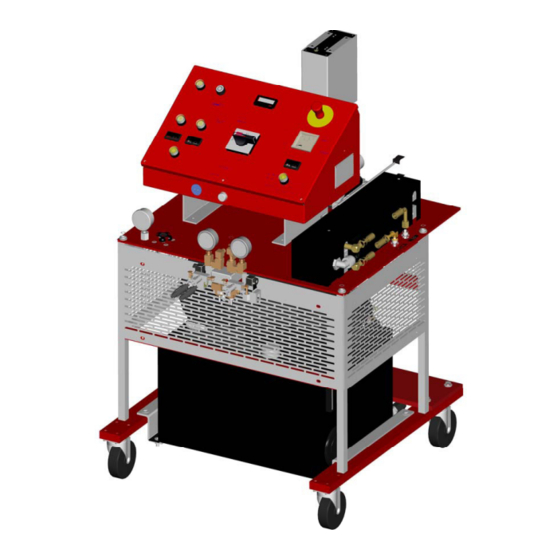
- Page 1 MH II Dispensing System 5845 WEST 82ND STREET INDIANAPOLIS, INDIANA 46278 U.S.A. Phone (317) 875-5592 (317) 875-5456 Email gcisales@glascraft.com www.glascraft.com...
-
Page 2: Table Of Contents
Table Of Contents Introduction About This Manual..............................1 Parts & Illustrations MH II System List / Options / Repair Parts Kits ....................... 2 System Specifications .............................. 3 22850-XX MH II System Console ..........................4 22850-XX MH II System Assembly ........................... 6 22852-XX MH II Control Box Assembly ........................ -
Page 3: Introduction
Introduction About This Manual The information in this document is intended only to indicate the components and their normal working Before operating, maintaining or servicing any relationship typical use. Each assembly should be GlasCraft system, read and understand all of the directed by a GlasCraft distributor or technical and safety literature provided with GlasCraft made from the GlasCraft assembly instructions pro-... -
Page 4: Parts & Illustrations
Parts & Illustrations MH II Dispensing System 25lbs.(12kg.)/min. Spray or Pour Dispensing System Includes 22850-XX MH II Dispensing System 17254-XX Probler Gun Assembly • W/ Round Spray Mixing Chamber 18006-01 Whip Hose Assembly 19524-01 Medium Pressure Heated Hose Assembly 17661-XX... -
Page 5: System Specifications
System Specifications Material Ratio: 1:1 (Fixed) Material Viscosity: 200- 2000 Centipoise (Cps) At Operating Temperatures Output: .021 GPS .042 GPC Operating Temperatures: 32º F ( 0º C ) - 190º (88 º C ) Operating Psi: 3000 Psi. Max (Over Psi Switches Set) Hoses: 2200 PSI. -
Page 6: 22850-Xx Mh Ii System Console
22850-XX MH System Console... - Page 7 22850-XX MH System Console Controls power and door; handle must point 1 to energize power , handle must point to 0 to open control MAIN POWER SWITCH box door. White pilot indicates when lighted, that the main power is on. To stop all functions, push down on red button.
-
Page 8: 22850-Xx Mh Ii System Assembly
22850-XX MH II System Assembly REVISION P... - Page 9 22850-XX MH II System Assembly * NOTE: Use the 22145-05 power pack with 22850-01. REVISION P...
- Page 10 22850-XX MH II System Assembly REVISION P...
- Page 11 22850-XX MH II System Assembly REVISION P...
- Page 12 22850-XX MH II System Assembly REVISION P...
- Page 13 22850-XX MH II System Assembly REVISION P...
- Page 14 22850-XX MH II System Assembly REVISION P...
- Page 15 22850-XX MH II System Assembly Parts List PART PART DESCRIPTION DESCRIPTION NUMBER NUMBER RM-856-04 ELBOW FITTING 21819-00 LIVE WIRE DECAL RS-118 ISO DECAL 21835-00 PUMP ASSEMBLY RS-119 POLY DECAL 21847-00 CE PLATE 10009-04 ELBOW FITTING 21881-00 PRESSURE GAUGE 10009-06 ELBOW FITTING...
- Page 16 22850-XX MH II System Assembly Parts List PART DESCRIPTION PART NUMBER DESCRIPTION NUMBER 22706-16 SCREW 7966-10 PIPE FITTING 22707-00 TRANSFORMER COVER 7966-17 PIPE FITTING 22716-02 HOLE PLUG 8155-40C SCREW 22851-00 BOTTOM BRACKET 8155-80C SCREW 22852-XX CONTROL BOX ASSEMBLY 8156-32C SCREW...
-
Page 17: 22852-Xx Mh Ii Control Box Assembly
22852-XX MH II Control Box Assembly REVISION N... - Page 18 22852-XX MH II Control Box Assembly REVISION N...
- Page 19 22852-XX MH II Control Box Assembly REVISION N...
- Page 20 22852-XX MH II Control Box Assembly REVISION N...
- Page 21 22852-XX MH II Control Box Assembly REVISION N...
-
Page 22: 22852-Xx Mh Ii Schematic
22852-XX MH II System Generic Ladder Schematic REVISION N... - Page 23 22852-XX MH II Control Box Assembly REVISION N...
-
Page 24: 22852-01 Mh Ii Schematic
22852-01 MH II System Ladder Schematic REVISION F... - Page 25 22852-XX MH II System Assembly Parts List PART PART DESCRIPTION DESCRIPTION NUMBER NUMBER RS-118 ISO DECAL 21867-02 INSCRIPTION CAP BLACK RS-119 POLY DECAL 21867-03 INSCRIPTION CAP WHITE RS-121 HOSE DECAL 21867-04 INSCRIPTION CAP WHITE RS-124 MAIN DECAL 21867-05 INSCRIPTION CAP WHITE...
- Page 26 22852-XX MH II System Assembly Parts List PART DESCRIPTION NUMBER 3800-03 WIRE 3800-08 WIRE 4160-00 TERMINAL LUG RING 4342-04 ELBOW FITTING 5307-01 CONDUIT NUT 5307-03 CONDUIT NUT 6782-03 FITTING 7361-00 TERMINAL RING LUG 7486-05 FLAT WASHER 7486-11 FLAT WASHER 7486-27...
-
Page 27: 21835-00 Fluid Section Assembly
21835-00 Fluid Section Assembly REVISION E REPAIR KIT: 21845-00... - Page 28 21835-00 Fluid Section Assembly Parts List PART DESCRIPTION QTY. NUMBER APS-119 FOOT VALVE SEAT APS-128 CHROME BALL APS-133 SST BALL FS-110 NYLON PISTON GUIDE P33-11 PUMP BASE 1005-02 SNAP RING 13867-43 O-RING 13867-44 O-RING 18219-00 PUMP CYLINDER 18227-00 AIRLESS PUMP HEAD 18289-00 PUMP TIE ROD 18295-01...
-
Page 29: 22075-00 Heat Exchanger Assembly
22075-00 Heat Exchanger Assembly REVISION J... - Page 30 22075-00 Heat Exchanger Assembly REVISION J...
- Page 31 22075-00 Heat Exchanger Assembly Note When replacing thermocouple p/n: 21074-00, use kit p/n: 21214-01. Be sure thermocouple is touching heater element before tightening. REVISION J...
- Page 32 22075-00 Heat Exchanger Assembly Parts List PART DESCRIPTION QTY. NUMBER RS-118 ISO DECAL RS-119 POLY DECAL 11021-23 PIPE PLUG 20188-20C SCREW 21038-00 HARD FIBER WASHER 21056-32C SCREW 21057-01 GLASS FIBER WASHER 21061-01 WIRE 21061-02 WIRE 21065-16C SCREW 21068-06C SCREW 21071-01 HARD FIBER WASHER 21071-02 HARD FIBER WASHER...
-
Page 33: 19524-01 Medium Pressure Hose Assembly
19524-01 MH II Hose Assembly PART DESCRIPTION NUMBER T4-155-02 3/8 MATERIAL HOSE 10262-04 NYLON FLUID HOSE 11745-10 HEAT SHRINK TUBING SHRINK 13424-03 CABLE TIE 13424-05 CABLE TIE 14902-12 HOSE CLAMP 15998-02 NEOPRENE TUBING 17895-01 UNION FITTING 17896-01 UNION TUBE FITTING... -
Page 34: Typical System Layout
Typical System Layout Diagram... -
Page 35: Typical System Hose Connections For 50 Ft
Typical System Hose Connection 50 Ft. Application... -
Page 36: Typical System Connections For 100-300 Ft
Typical System Hose Connection 100-300 Ft. Applications... -
Page 37: Safety
Safety Safe Handling And Use Of Urethane Foam Organic Peroxides and Dual Component Coatings. Local Equipment codes and authorities also have standards to be followed in the operation of your spraying equipment. Chemical Introduction manufacturer’s recommendations should be obtained and considered. Your insurance carrier will be helpful in Any tool, if used improperly, can be dangerous. - Page 38 Safety To avoid moisture contamination, do not open contain- Equipment capable of withstanding pres- ers until ready for use. After use, the remaining material sure. When HHC solvents contact aluminum or galva- should be re-sealed in the original container and stored in nized parts inside a closed container, such as a pump, areas away from moisture.
-
Page 39: Instructions
Safety WARNING Adequate ventilation (as covered in OSHA Section 1910.94 and NFPA No. 91) is important wherever sol- If you are now using Halogenated Hydrocarbon solvents vents are stored or used, to minimize, confine and ex- in pressurized fluid systems having aluminum or galva- haust the solvent vapors. - Page 40 Safety If a person accidentally swallows isocyanate, large In industrial and contractor applications, it is advisable amounts of water should be swallowed immediately. to run frequent tests to determine the exact concentra- Vomiting should then be induced by patient sticking his tion of isocyanate vapor in the air.
- Page 41 Installation Assembly Instructions NOTE The GlasCraft System is factory assembled. If any questions arise concerning air or electrical connections, please refer to illustrations located in the forward portion of this User Manual or contact your GlasCraft distribu- tor. Fluid Line Connection The material hoses that bring Isocyanate and Poly- ol chemicals and the air from the machine to the gun should be connected as follows.
- Page 42 Installation Install thermocouple at tee fitting. a. Feed 12’ line through hose. b. Nut & Ferrules will lock into fitting. c. Tighten nut 1-1/4 turns past finger tight. d. Plug thermocouple into control box. Note: When replacing thermocouple use kit p/n: 21214-01. TO AIR MANIFOLD 6.
-
Page 43: Optional Transfer Pump Installation / Air Dryer Kit
Installation Optional Transfer Pump Installation P/n: 17661-01 Remove large drum bunghole cover and install material transfer pump bung adapter. Carefully lower the transfer pump into the drum until it touches the bottom of the drum. Raise the pump 1/4 to 1/2 inch and tighten bung adapter securely. -
Page 44: Electrical Connections
Installation Hydraulic Power Pack Electrical Connections The hydraulic pack tank is empty when shipped NOTE MUST from GlasCraft. The tank be filled Electrical connections must be checked on a periodic before operation. basis. Tank Capacity: 20 GAL. / 75.5 Liter 200/208 volt single phase Recommended Hydraulic Fluid: ISO grade 32, 46, or 68. -
Page 45: Operation
Operation WARNING If the transfer pumps can not move material adequately enough to properly prime the system it may be Never leave machine unattended while system power is necessary to start the hydraulic power pack. on or system is running. System running is defined as: preheat cycle of the hose a. - Page 46 Operation NOTE Remove ISO & POLY side blocks from gun. MAKE SURE VALVES ARE OFF! Remember to dispense one to two gallons of material to clear the system of grease and plasticizer that was used during factory testing. Close manual material valves. Material pressure gauges should now register approximately equal pressure.
- Page 47 Operation Turn on hose control: Turn on Hydraulic Power Pack a. Push in the green button. b. Press either up or down arrow buttons on the controller until desired temperature setting is achieved. For Programing Use Only Up & Down Buttons Green Power On Button...
-
Page 48: Over Pressure System Protection
Operation Turn purge air and material valves ON at the gun. Relieve any excess pressure by triggering the gun. NOTE The Emergency Stop Switch is located on the top right side of the Box Panel, when depressed, it will shut down the pow- er and activate the Air Dump Valve. -
Page 49: Over Pressure Problem Correction
Operation In an over pressure situation, the system will remain CAUTION shut down until it is manually reset. If you do not understand the electrical hook-up described above, consult your local GlasCraft distributor OR a quali- At this point, it is necessary to determine if the problem fied electrician. -
Page 50: System Shut Down
Operation System Shut-Down Turn main power switch off. Flip “retract” switch from “run” position. Refer to gun manual for proper Gun maintenance. Reduce Hydraulic Pressure Knob setting to ZERO. Trigger gun to send pumps into full downstroke. Visually inspect entire system for leaks. Turn off hydraulic power pack. -
Page 51: System Daily Start-Up
Operation System Daily Start-Up Uncoil hose. Once the hose temperature reaches 120º, It’s ok to turn on the primary heaters and set temperature to material suppliers specifications. Check desiccant dryer beads to insure they are still purple and have not changed to pink. Power on Check and lube top of the fluid section. - Page 52 Operation System Daily Start-Up Increase Hydraulic pressure to desired pressure. Pressure Knob Perform Probler / Probler P2 side block seal integ- rity test. Perform Probler / Probler P2 high-pressure ball valve test. READY TO SPRAY!
-
Page 53: Limited Warranty Policy
Limited Warranty Policy GLASCRAFT, INC. (“GlasCraft”) warrants to the original Purchaser of GlasCraft manufactured equipment and parts, that all GlasCraft manufactured equipment and parts will conform to their published written specifications and be free of defects in workmanship and material for a period of one (1) year from the original date of installation. GlasCraft makes no warranty to anyone other than the original Purchaser. -
Page 54: Notes
Notes... - Page 55 Notes...
- Page 56 Notes...
- Page 57 Notes...
-
Page 58: If You Have An Equipment Problem
If You Have An Equipment Problem.... If you have a problem that requires Distributor or GlasCraft Service Department help, gather the following information BEFORE you pick-up the telephone. Model No. Serial No. SPRAY GUN MATERIAL PUMP TYPE OF MATERIAL BEING SPRAYED SYSTEM GAUGE PRESSURES ISO HEATER GAUGE POLY HEATER GAUGE... -
Page 59: For Your Reference
RESIN TRANSFER MOLDING SYSTEM ------------------------------------------------------------------------------------------------------------------- Micro ll, Maxi ll, Super Maxi, SPRAY, POUR & INJECT Mini III, MX, MX II, MH & MH II FIXED & VARIABLE RATIO SYSTEMS and ...featuring the patented Probler Spray/Pour Gun EQUIPMENT FOR POLYURETHANE FOAMS,... - Page 60 Quality and Performance… GENUINE GLASCRAFT 5845 WEST 82nd STREET INDIANAPOLIS, INDIANA 46278 U.S.A. www.glascraft.com Phone (317) 875-5592 GC-1267 (317) 875-5456 REVISION P E-Mail sales@glascraft.com...
Need help?
Do you have a question about the MH II and is the answer not in the manual?
Questions and answers