
Subscribe to Our Youtube Channel
Related Manuals for PIETRO FIORENTINI APERFLUX 851


Summary of Contents for PIETRO FIORENTINI APERFLUX 851
- Page 1 PRESSURE REGULATOR APERFLUX 851 TECHNICAL MANUAL MT049 INSTALLATION, COMMISSIONING AND MAINTENANCE INSTRUCTIONS | sales@mvandc.com | Phone: 877.566.3837 | Fax: 925.407.2903 www.mvandc.com...
- Page 2 TECHNICAL MANUAL MT049 AR 73 304/A CONTROL PRESSURE OUTLET PRESSURE INLET PRESSURE APERFLUX 851 302/A Issue October 2002 | sales@mvandc.com | Phone: 877.566.3837 | Fax: 925.407.2903 www.mvandc.com...
- Page 3 TECHNICAL MANUAL MT049 DECLARATION OF CONFORMITY The PIETRO FIORENTINI SPA with registered office in Milan (Italy) – via Rosellini, 1, declares under its sole responsibility that the apparatus series Aperflux 851 bearing the CE marking showed in this manual are designed, manufactured, tested and inspected in accordance with the provisions of Pressure Equipment Directive 97/23/EC (PED).
- Page 4 | sales@mvandc.com | Phone: 877.566.3837 | Fax: 925.407.2903 www.mvandc.com...
- Page 5 TECHNICAL MANUAL MT049 PRECAUTIONS GENERAL PRECAUTIONS - The apparatus described in this manual is a device subject to pressure installed in systems under pressure; - the apparatus in question is normally installed in systems for transporting flammable gases (natural gas, for example).
- Page 6 CONFORMITY TO DIRECTIVE 97/23/EC (PED) Pressure regulator Aperflux 851 are classified as fail open regulators according to the standard EN 334 therefore they are pressure accessory according to directive 97/23/EC (PED). The incorporated safety device monitor PM/819 (as well as the in-line monitor REFLUX 819) being classified as fail close regulators according to the standard EN 334 is as safety accessory according PED, therefore it can be used both as pressure accessory and safety accessory to PED.
-
Page 7: Table Of Contents
APERFLUX 851 REGULATOR MAINTENANCE PROCEDURE........ - Page 8 | sales@mvandc.com | Phone: 877.566.3837 | Fax: 925.407.2903 www.mvandc.com...
-
Page 9: Introduction
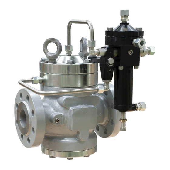
MAIN FEATURES The Aperflux 851 pressure regulator is a regulator of the piloted type for medium and high pressures. The Aperflux 851 is a fail open type regulator and therefore opens in the event of: - rupture of the main diaphragm;... - Page 10 TECHNICAL MANUAL MT049 Connections to be made Ref. No. for the connections by the customer Fig. 1 | sales@mvandc.com | Phone: 877.566.3837 | Fax: 925.407.2903 www.mvandc.com...
- Page 11 TECHNICAL MANUAL MT049 302/A PILOT vent vent Fig. 2A | sales@mvandc.com | Phone: 877.566.3837 | Fax: 925.407.2903 www.mvandc.com...
- Page 12 TECHNICAL MANUAL MT049 304/A PILOT vent Fig. 2B | sales@mvandc.com | Phone: 877.566.3837 | Fax: 925.407.2903 www.mvandc.com...
-
Page 13: Ar73 Regulating Valve
TECHNICAL MANUAL MT049 AR73 REGULATING VALVE The AR73 regulating valve is an adjustable flow regulation device. Its function is to adjust and differentiate the regulator's response times so as to optimize its operation. Small openings of the valve result in a greater regulating precision of the regulator, but also in a greater sensitivity to instability phenomena (pumping);... -
Page 14: Setting Springs
TECHNICAL MANUAL MT049 SETTING SPRINGS The Aperflux 851 regulator uses the 302/A, 304/A, 305/A and 307/A pilots. The regulation range of the different pilots is given in the tables below. Tab. 1 302/A Pilot setting springs Code Colour Setting range in bar... -
Page 15: Installation
TECHNICAL MANUAL MT049 INSTALLATION GENERAL Pressure regulator does not require any supplementary upstream safety accessory for protection against overpressure compared with its design pressure PS, when upstream reducing station is sized for a max downstream incidental pressure MIPd ≤ 1,1 PS. Before installing the regulator it is necessary to ensure that: - the regulator can be inserted in the space provided and that subsequent maintenance operations will be sufficiently practicable;... - Page 16 TECHNICAL MANUAL MT049 TAB. 5 CONNECTING THE APPARATUSES The connections between the apparatus and the main piping must be made using stainless steel pipe with minimum internal diameter of 8 mm. IN-LINE INSTALLATION Regulator Pilot discharge Sensing line Control pressure gauge Bleed cock On/Off valve INSTALLATION AT RIGHT ANGELS...
-
Page 17: Accessories
TECHNICAL MANUAL MT049 TAB. 6 DETAIL OF MULTIPLE TAKE - OFF WITH OF THE IMPULSE TAKE - OFF REFERENCE NUMBERS 1 and 2 Connect to regulators heads 3 and 4 Connect to pilots 5 and 6 Connect to accelerator and slam-shut The regulator must be installed in the line with the arrow on the body pointing in the gas flow direction. -
Page 18: Direct Installation In The Line
TECHNICAL MANUAL MT049 Obviously the quantity of gas released depends on the extent of the overpressure with respect to the set-point. The different models of relief valve available are all based on the same operating principle which is illustrated below with reference to the valve VS/AM 56 (fig. -
Page 19: Installation With On/Off Valve
TECHNICAL MANUAL MT049 3.1.2 INSTALLATION WITH ON/OFF VALVE (FIG. 7) 1) Close the on-off valve 16. 2) Connect a controlled auxiliary pressure to the nipple 17 and increase it slowly up to the value envisaged for intervention. 3) Check the intervention of the relief valve and adjust if necessary by turning the adjustament plug 13 appropriately (clockwise to increase and anticlockwise to decrease). -
Page 20: Modularity
This is a device (fig. 9) which immediately blocks the gas flow if, following some kind of failure, the downstream pressure reaches the set-point for its intervention, or is operated manually. On the APERFLUX 851 regulator, it is possible to have the SB/82 slam-shut incorporated both with the service regulator and on the one functioning as in-line monitor. -
Page 21: 4.2.1 Sb/82 Slam-Shut Operation
TECHNICAL MANUAL MT049 4.2.1 SB/82 SLAM-SHUT OPERATION The SB/82 slam-shut device (see fig. 10) consists of an obturator A, a releasing lever system, a control head B and a resetting system which is controlled manually by the lever C. The pressure in the circuit to control acts on the diaphragm in the control head B. - Page 22 TECHNICAL MANUAL MT049 CONTROL DEVICE Mod. 102 - 103 - 104 - 105 Mod. 106 - 107 - 108 - 109 Fig. 11 SLAM-SHUT CONTROL HEADS MOD. 102 -106 MOD. 103 -106 MOD. 104 -107 MOD. 105-108 - 109 Fig. 12 | sales@mvandc.com | Phone: 877.566.3837 | Fax: 925.407.2903 www.mvandc.com...
-
Page 23: Sb/82 Slam-Shut Setting Springs
TECHNICAL MANUAL MT049 4.2.2 TAB. 8 SB/82 SLAM-SHUT SETTING SPRINGS SETTING RANGE in bar 104- 105- Spring characteristics Code Colour De Lo bar/min bar/max bar/min bar/max bar/min bar/max bar/min bar/max 1 2700565 WHITE 2 2700314 YELLOW 1,3 13 15 0,04 ÷ 0,1 0,2 ÷... -
Page 24: Incorporated Hb/97 Slam-Shut Valve
This is a device (fig.13) which immediately blocks the gas flow if, following some kind of failure, the downstream pressure reaches the set-point for its intervention, or is operated manually. On the Aperflux 851 regulator, it is possible to have the HB/97 slam-shut incorporated both with the service regulator or on the one functioning as in-line monitor. -
Page 25: Hb/97 Operation
TECHNICAL MANUAL MT049 4.3.1 HB/97 OPERATION (FIG. 14) The cut-off device consist principally of the following parts: • on/off valve (pos. 12); • single action pneumatic actuator (pos. 11); • line-off device (from pos.1 until pos. 10); When there is no pressure, the valve obturator is held in the closed position by the spring, (pos. 13), and rests on the valve seat. - Page 26 TECHNICAL MANUAL MT049 CONTROL DEVICE Mod. 103 - 104 - 105 Mod. 105/92 Fig. 15 SLAM-SHUT CONTROL HEADS Mod. 103 Mod. 104 - 105 Fig. 16 | sales@mvandc.com | Phone: 877.566.3837 | Fax: 925.407.2903 www.mvandc.com...
-
Page 27: Hb/97 Slam-Shut Setting Springs
TECHNICAL MANUAL MT049 4.3.2 TAB. 9 HB/97 SLAM-SHUT SETTING SPRINGS SETTING RANGE in bar Spring characteristics SH1190/103 SH1190/104 SH1190/105 SH1190/105/92 Code Colour bar/min bar/max bar/min bar/max bar/min bar/max bar/min bar/max De Lo d 0.4 ÷ 1 1 2700513 8.5 10.5 2 2700713 GREEN 2.3 8.5 10.5... -
Page 28: Monitor
Installation of accelerator is recommended fo use as safety accessory according to Directive 97/23/EC (PED). Two alternative solutions are offered for this safety device associated to Aperflux 851 regulators: incorporated monitor or in-line monitor. 4.4.1 PM/819 INCORPORATED MONITOR This emergency device (fig. -
Page 29: 4.4.2 In-Line Monitor
With this kind of application, the emergency regulator is installed upstream from the service one. Depending on the specific requirements of the system, the regulator acting as monitor can be chosen between: - Reflux 819 regulator (fig. 18); - Aperflux 851 regulator, the same in all ways as the main regulator (fig. 19). R14/A 204/A... -
Page 30: Setting Springs
TECHNICAL MANUAL MT049 SETTING SPRINGS The REFLUX 819 regulator and the monitor PM/819 uses the 204/A, 205/A and 207/A pilots. The regulation range of the different pilots is given in the tables below. Tab. 10 Pilot 204/A, 204/A/1 Code Colour Setting range in bar 2701260 WHITE... -
Page 31: Start Up
TECHNICAL MANUAL MT049 START UP GENERAL After installation, check that the inlet/output on-off valves, any by-pass and the bleed cock are closed. Before starting up, checking is recommended to ascertain that the conditions of use are in conformity with the specifications of the equipment. -
Page 32: Gas Input, Control Of External Tightness And Setting
TECHNICAL MANUAL MT049 The list of symbols used and their meanings are listed below: = According to Directive PED Pemax= maximum inlet operating pressure of the apparatus bpe= range of variability of the inlet pressure of the pressure regulator in normal operating conditions PS= maximum pressure which can be supported by the structure of the body of the apparatus in safety conditions Wa= range of setting of the pressure regulator/pilot/pre-regulator which can be obtained using the parts and the setting spring fitted at the moment of testing (without changing any components of the apparatus, that is). -
Page 33: Comissioning The Regulator
TECHNICAL MANUAL MT049 In installations consisting of two lines, we suggest commissioning one line at a time, starting from the one with the lower set-point, known as the “reserve” line. The set-points of the apparatuses in this line will obviously deviate from those specified in the table 13. -
Page 34: Commissioning The Regulator With Incorporated Sb/82 Slam-Shut
TECHNICAL MANUAL MT049 COMMISSIONING THE REGULATOR WITH INCORPORATED SB/82 SLAM-SHU T (FIG. 23) If there is also a relief valve in the line, refer to par. 3.1 to check it. Check and adjust the intervention of the slam-shut 7 as follows: Fig. - Page 35 TECHNICAL MANUAL MT049 Rest position (A and B in communication) Safety device Control position (A and C in communication) Chamber with controlled pressure Euvironment with pressure to be checked Fig. 24 B) On devices without the "push" valve (fig. 25) we recommend separately connecting the control head to a controlled auxiliary pressure and repeat the operations described above.
-
Page 36: Commissioning The Regulator With Incorporated Pm/819 Monitor And
TECHNICAL MANUAL MT049 ATTENTION: At the end of the operation, reconnect the control head to the downstream pressure take-off N.B.: The intervention tests should be repeated at least every 6 months. On completion of the slam-shut tests, proceed as follows: 1) Ensure that the slam-shut is in the closed position. -
Page 37: Commissioning The Regulator With Reflux 819 In-Line Monitor With Incorporated
TECHNICAL MANUAL MT049 1) Completely increase the setting of the pilot 3 by turning the ring 10 clockwise (fig. 22). 2) Completely increase the setting of the accelerating valve by turning the adjustment screw 17 (fig. 8) clockwise. 3) Close the AR73 valve in position 0. 4) Partially open the bleed cock 6. - Page 38 TECHNICAL MANUAL MT049 Control and adjust slam-shut 7 operation as follows: A) For slam-shut devices connected to the downstream piping by means of the three-way "push" valve 11, proceed as follows (fig. 24): - connect a controlled auxiliary pressure to path C; - stabilize this pressure at the regulator set point value;...
-
Page 39: Commissioning The Regulator Plus Aperflux 851 In-Line Monitor With Incorporated
AR73 valve. 20) It is reccomended to check that the flow of the line stops when the slam-shut is tripped manually. COMMISSIONING THE REGULATOR PLUS APERFLUX 851 IN LINE MONITOR WITH INCORPORATED SB/82 SLAM-SHUT (FIG. 29) Fig. - Page 40 TECHNICAL MANUAL MT049 pressure. If necessary, increase the intervention value for pressure increase or decrease by turning the rings 14 or 15 respectively clockwise; vice versa to reduce the value. - check proper operation by repeating the operations at least 2-3 times. B) With devices without the "push"...
- Page 41 TECHNICAL MANUAL MT049 TAB. 13: Settings of in-line apparatuses consisting of Regulator APERFLUX 851 + Monitor + Slam-shut + Relief valve Set-point Set-point Set-point Set-point Set-point Set-point Regulator MONITOR ACCELERATING RELIEF-VALVE SLAM-SHUT Max SLAM-SHUT Min (Pas) bar VALVE Pas x 1.1 Pas x 1.2...
-
Page 42: Trouble-Shooting
Tampering with the apparatuses by unsuitable personnel relieves us from all responsibility of any kind. You must therefore train your maintenance personnel or avail yourself of the service centres officially authorised by us. APERFLUX 851 REGULATOR (FIG. 30, 31 and 32) TAB. 14 PROBLEM POSSIBLE CAUSES... -
Page 43: Pm/819 Monitor
TECHNICAL MANUAL MT049 PROBLEM POSSIBLE CAUSES APPARATUS REMEDY Incorrect adjustment AR73 (32) Adjust Formation of ice on the valve Increase the pilot circuit gas input temperature 302/A PILOTA (fig. 32) Valve obstructed by dirt Clean and check the AR73 filter Pressure drop cartridge No pressure upsteam... -
Page 44: Regulator Sb/82 Slam-Shut
TECHNICAL MANUAL MT049 PROBLEM POSSIBLE CAUSES APPARATUS REMEDY Diaphragm [16] ruptured Replace 204/A PILOT (fig. 34) Motorisation line to the Repair regulator broken Obturator blocked Clean and check movement Diaphragm [50] ruptured Replace Pressure drop Guide ring [36] damaged Replace REGULATOR (fig. -
Page 45: Maintenance
TECHNICAL MANUAL MT049 MAINTENANCE GENERAL Periodical inspection and maintenance shall be carried out according to the regulations in force (kind and frequencies). Before carrying out any operation it is important to ascertain that the regulator has been cut off both upstream the regulator and the on/off valves. -
Page 46: Aperflux 851 Regulator Maintenance Procedure
TECHNICAL MANUAL MT049 APERFLUX 851 REGULATOR MAINTENANCE PROCEDURE Fig. 30 | sales@mvandc.com | Phone: 877.566.3837 | Fax: 925.407.2903 www.mvandc.com... - Page 47 TECHNICAL MANUAL MT049 Fig. 31 | sales@mvandc.com | Phone: 877.566.3837 | Fax: 925.407.2903 www.mvandc.com...
- Page 48 TECHNICAL MANUAL MT049 302/A PILOT AR73 FLOW REGULATION VALVE Fig. 32 | sales@mvandc.com | Phone: 877.566.3837 | Fax: 925.407.2903 www.mvandc.com...
- Page 49 TECHNICAL MANUAL MT049 Procedure for the disassembly, complete replacement of spares parts and reassembly of the “APERFLUX 851” pressure regulator with 302/A pilot + AR73 (PROGRAMMED PREVENTIVE MAINTENANCE) PRELIMINARY OPERATIONS Put the regulator into conditions of safety; Ensure that the upstream and downstream pressures are 0.
- Page 50 TECHNICAL MANUAL MT049 18) Reassemble the bottom blind flange, pos. , and fix the screws, pos. 18a)* Reinstall the flange, pos. , on the body of the regulator and fix the screws, pos. 19) Reassemble the valve seat, pos. 20) Reassemble the intermediate flange, pos. , along with the diaphragm protection grill, pos.
- Page 51 TECHNICAL MANUAL MT049 45) Reassemble the bottom flange, pos. , on the pilot body pos. and fix the screws, pos. 46) Reassemble the impulse diaphragm assembly, screwing in the nut, pos. 47) Reassemble the ring, pos. , the impulse diaphragm assembly, the spring, pos. , and the pilot top flange, pos.
-
Page 52: Pm/819 Monitor Maintenance Procedure
TECHNICAL MANUAL MT049 PM/819 MONITOR MAINTENANCE PROCEDURE Fig. 33 | sales@mvandc.com | Phone: 877.566.3837 | Fax: 925.407.2903 www.mvandc.com... - Page 53 TECHNICAL MANUAL MT049 VERSIONS Fig. 33/A | sales@mvandc.com | Phone: 877.566.3837 | Fax: 925.407.2903 www.mvandc.com...
- Page 54 TECHNICAL MANUAL MT049 204/A + R14/A PILOT DOWNSTREAM INLET PRESSURE PILOT FEED R14/A Fig. 34 | sales@mvandc.com | Phone: 877.566.3837 | Fax: 925.407.2903 www.mvandc.com...
- Page 55 TECHNICAL MANUAL MT049 PM/819 MONITOR (FIG. 33) Disconnect the connection pipes between the regulator and monitor and the respective pilot units, and between the latter and the downstream pressure take-offs. Remove the screws which secure the reduction assembly of the monitor to the body, making sure that the weight of the reduction assembly itself can be sustained.
- Page 56 TECHNICAL MANUAL MT049 DISASSEMBLING THE 204/A PILOT (FIG. 34) Slacken the lock nut Slacken the adjustment screw for its complete stroke by turning it anticlockwise. Remove the pilot plug Remove the spring support , the spring and the spring support from the pilot.
- Page 57 TECHNICAL MANUAL MT049 27) From the preregulator body , remove the preregulator plug , the reinforced gasket the filter , the obturator guide and the guide ring 28) Clean and carefully check that the obturator is in a good state. 29) Replace all the components which are part of the spare parts kit.
-
Page 58: Slam-Shut Device Sb/82 Maintenance Procedure
TECHNICAL MANUAL MT049 SLAM-SHUT DEVICE SB/82 MAINTENANCE PROCEDURE VERSIONS Fig. 35 | sales@mvandc.com | Phone: 877.566.3837 | Fax: 925.407.2903 www.mvandc.com... - Page 59 TECHNICAL MANUAL MT049 SLAM-SHUT CONTROL HEADS MOD. 102 -106 MOD. 103 -106 MOD. 104 -107 MOD. 105-108 - 109 | sales@mvandc.com | Phone: 877.566.3837 | Fax: 925.407.2903 www.mvandc.com...
- Page 60 TECHNICAL MANUAL MT049 SB/82 SLAM-SHUT (FIG. 35) Check that the slam-shut is in the closed position. Disconnect the pipe between the downstream pressure take-off and the head of the slam-shut pressure switch. Slacken the fixing screws, pos. , so as to partially slacken the spring, pos. ;...
-
Page 61: Final Operation
TECHNICAL MANUAL MT049 FINAL OPERATIONS TIGHTNESS AND SETTING CHECK Very slowly open the on/off valve upstream from the regulator and, using a foam solution or the like, check: • the tightness of the external surfaces of the regulator and of the pilot; •... - Page 62 TECHNICAL MANUAL MT049 Tab. 17 MAINTENANCE WRENCHES APERFLUX 851 PRESSURE REGULATORS WITH 30.../A PILOT AND AR73 Combination spanner Adjustable spanner Compass pin wrench Box spanner Hexagon or allen key Hexagonal T key Hexagonal socket T wrench Phillips screwdriver Flat head screwdriver...
- Page 63 TECHNICAL MANUAL MT049 Tab. 18 MAINTENANCE WRENCHES FOR APERFLUX 851 PRESSURE REGULATORS WITH 30.../A PILOT AND AR73 Combination spanner Adjustable spanner Compas pin wrench Box spanner Hexagon or allen key Hexagonal tee key Hexagonal socket T wrench Phillips screwdriver Flat head screwdriver...
-
Page 64: Weight Of The Components
TECHNICAL MANUAL MT049 9. 0 WEIGHT OF THE COMPONENTS TAB. 19 WEIGHT OF THE COMPONENTS IN KG. 1” 2” 3” 4” 6” 8” 10” 2,750 4,200 0,300 0,300 0,650 1,200 2,100 2,800 5,300 2,500 3,950 10,200 16,200 6,200 8,500 20,900 0,150 0,400 0,760... -
Page 65: 10.0 List Of Recommended Spares
TECHNICAL MANUAL MT049 10.0 LIST OF RECOMMENDED SPARES | sales@mvandc.com | Phone: 877.566.3837 | Fax: 925.407.2903 www.mvandc.com... - Page 66 TECHNICAL MANUAL MT049 APERFLUX 851 PRESSURE REGULATOR DN: 1” - 2” Fig. A | sales@mvandc.com | Phone: 877.566.3837 | Fax: 925.407.2903 www.mvandc.com...
- Page 67 TECHNICAL MANUAL MT049 VERSION VERSION DN: 3 ÷ 10” Fig. B N. OF PIECES 1” - 2” 3” ÷ 10” POS. DESCRIPTION Diaphragm O. Ring O. Ring O. Ring O. Ring | sales@mvandc.com | Phone: 877.566.3837 | Fax: 925.407.2903 www.mvandc.com...
- Page 68 TECHNICAL MANUAL MT049 APERFLUX 851 PRESSURE REGULATOR + DB/851 DN: 1” - 2” Fig. C | sales@mvandc.com | Phone: 877.566.3837 | Fax: 925.407.2903 www.mvandc.com...
- Page 69 TECHNICAL MANUAL MT049 VERSIONS VERSION VERSION DN: 3” ÷ 8” DN: 10” Fig. D Fig. E N. OF PIECES 1” - 2” 3” - 4” 6” 8” 10” POS. DESCRIPTION DB 851 DB 886 DB 851 DB 886 DB 851 DB 886 DB 851 DB 886 DB 851 DB 886 Copper O.
- Page 70 TECHNICAL MANUAL MT049 PM/819 MONITOR DN: 2” | sales@mvandc.com | Phone: 877.566.3837 | Fax: 925.407.2903 www.mvandc.com...
- Page 71 TECHNICAL MANUAL MT049 VERSIONS VERSION VERSION DN: 10” DN: 1” VERSION VERSION DN: 3” - 4” DN: 6” ÷ 10” VERSION DN: 6” ÷ 10” | sales@mvandc.com | Phone: 877.566.3837 | Fax: 925.407.2903 www.mvandc.com...
- Page 72 TECHNICAL MANUAL MT049 N. OF PIECES 1” ÷ 4” 6” - 8” 10” POS. DESCRIPTION O. Ring O. Ring O. Ring O. Ring O. Ring O. Ring O. Ring O. Ring O. Ring O. Ring Diaphragm Guide ring O. Ring O.
- Page 73 TECHNICAL MANUAL MT049 … + SB/82 SLAM-SHUT DN: 2” VERSIONS VERSION VERSION DN: 3” - 4” - 6” - 8” DN: 1” | sales@mvandc.com | Phone: 877.566.3837 | Fax: 925.407.2903 www.mvandc.com...
- Page 74 TECHNICAL MANUAL MT049 VERSIONS VERSION DN: 4” - 6” - 8” VERSION DN: 10” | sales@mvandc.com | Phone: 877.566.3837 | Fax: 925.407.2903 www.mvandc.com...
- Page 75 TECHNICAL MANUAL MT049 VERSIONS SECTION A - A VERSION VERSION DN: 1” ÷ 4” DN: 1” ÷ 4” SECTION B - B VERSION VERSION DN: 6” - 8” - 10” DN: 6” - 8” - 10” | sales@mvandc.com | Phone: 877.566.3837 | Fax: 925.407.2903 www.mvandc.com...
- Page 76 TECHNICAL MANUAL MT049 CONTROL DEVICE Mod.: 102 - 103 - 104 - 105 Mod.: 106 - 107 - 108 - 109 | sales@mvandc.com | Phone: 877.566.3837 | Fax: 925.407.2903 www.mvandc.com...
- Page 77 TECHNICAL MANUAL MT049 CONTROL HEADS Mod.: 102-106 Mod.: 103-106 Mod.: 104-107 Mod.: 105-108 | sales@mvandc.com | Phone: 877.566.3837 | Fax: 925.407.2903 www.mvandc.com...
- Page 78 TECHNICAL MANUAL MT049 N. OF PIECES 1” 2” - 3” 4” ÷ 8” 10” POS. DESCRIPTION Reinforced gasket Guide ring Guide ring O. Ring O. Ring O. Ring O. Ring O. Ring O. Ring MOD. 102-103-104-105-106-107-108-109 N. OF PIECES POS. DESCRIPTION O.
- Page 79 TECHNICAL MANUAL MT049 HB 97 SLAM-SHUT DEVICE DN: 4” | sales@mvandc.com | Phone: 877.566.3837 | Fax: 925.407.2903 www.mvandc.com...
- Page 80 TECHNICAL MANUAL MT049 VARIANTE DN: 6” - 8” - 10” N. OF PIECES 4” 6” 8” 10” POS. DESCRIPTION Reinforced gasket O. Ring O. Ring O. Ring O. Ring O. Ring O. Ring O. Ring Guide ring O. Ring GACO ring Guide ring O.
- Page 81 TECHNICAL MANUAL MT049 LINE OFF DEVICE PART. A Three-ways valve PART. B Filter PART. C Pressure regulator PART. D Relief valve PART. E Slide valve PART. F Control device | sales@mvandc.com | Phone: 877.566.3837 | Fax: 925.407.2903 www.mvandc.com...
- Page 82 TECHNICAL MANUAL MT049 PART. B FILTER PART. B POS. DESCRIPTION N. OF PIECES Filter cartridge O. Ring O. Ring PART. D RELIEF VALVE PART. D POS. DESCRIPTION N. OF PIECES Plug | sales@mvandc.com | Phone: 877.566.3837 | Fax: 925.407.2903 www.mvandc.com...
- Page 83 TECHNICAL MANUAL MT049 Part. F CONTROL DEVICE Mod.: 103-104-105 Mod.: 105/92 | sales@mvandc.com | Phone: 877.566.3837 | Fax: 925.407.2903 www.mvandc.com...
- Page 84 TECHNICAL MANUAL MT049 Mod.: 103 MOD. 103 N. OF PIECES POS. DESCRIPTION Diaphgram Mod.: 104-105 MOD. 103-105 N. OF PIECES POS. DESCRIPTION O. Ring | sales@mvandc.com | Phone: 877.566.3837 | Fax: 925.407.2903 www.mvandc.com...
- Page 85 TECHNICAL MANUAL MT049 PILOTS MOD. 302/A-304/A + AR73 FLOW REGULATION VALVE Fig. B 302/A Fig. A | sales@mvandc.com | Phone: 877.566.3837 | Fax: 925.407.2903 www.mvandc.com...
- Page 86 TECHNICAL MANUAL MT049 N. OF PIECES POS. DESCRIPTION 302/A Pilot 304/A Pilot Diaphragm Obturator O. Ring O. Ring O. Ring Diaphragm O. Ring O. Ring O. Ring O. Ring O. Ring O. Ring O. Ring AR73 FLOW REGULATION VALVE N. OF PIECES POS.
- Page 87 TECHNICAL MANUAL MT049 204/A PILOT POS. DESCRIPTION N. OF PIECES 204/A 205/A 204/A/2/CS 204/A/1/CS 204/A/MO O. Ring Diaphragm Obturator O. Ring O. Ring O. Ring O. Ring O. Ring O. Ring | sales@mvandc.com | Phone: 877.566.3837 | Fax: 925.407.2903 www.mvandc.com...
- Page 88 TECHNICAL MANUAL MT049 R14/A PREREGULATOR INLET DOWNSTREAM PRESSURE PILOT FEED POS. DESCRIPTION N. OF PIECES Guide ring Reinforced gasket Diaphragm Filter O. Ring O. Ring O. Ring O. Ring | sales@mvandc.com | Phone: 877.566.3837 | Fax: 925.407.2903 www.mvandc.com...
- Page 89 TECHNICAL MANUAL MT049 WHEN ORDERING SPARE PARTS, PLEASE SPECIFY: FOR REGULATORS Type of regulator Dne (nominal input diameter) Pe (inlet pressure) Pa (outlet pressure) Works no. (Serial no.) Year of manufacture Type of fluid used Slam-shut (if assembled) Type of control head The no.
- Page 90 TECHNICAL MANUAL MT049 The data are not binding. We reserve the right to make modifications without prior notice. Pietro Fiorentini S.p.A. OFFICES: I-20124 MILANO Italy - Via Rosellini, 1 - Phone +39.02.6961421 (10 linee a.r.) - Fax +39.02.6880457 E-mail: sales@fiorentini.com I-36057 ARCUGNANO (VI) Italy - Via E.
- Page 91 TECHNICAL MANUAL MT049 MPAGINAZIONE E TAMPA A CURA DI (VI) ONTECCHIO AGGIORE 2002 TTOBRE Redazione a cura di: Pietro Bottari Copyright © 2002 - Pietro Fiorentini S.p.A. | sales@mvandc.com | Phone: 877.566.3837 | Fax: 925.407.2903 www.mvandc.com...
- Page 92 | sales@mvandc.com | Phone: 877.566.3837 | Fax: 925.407.2903 www.mvandc.com...
Need help?
Do you have a question about the APERFLUX 851 and is the answer not in the manual?
Questions and answers