PIETRO FIORENTINI Aperflux 851 Use & Maintenance
High medium pressure gas regulator
Hide thumbs
Also See for Aperflux 851:
- Installation, commissioning and maintenance instructions (92 pages) ,
- Technical manual (83 pages)

Related Manuals for PIETRO FIORENTINI Aperflux 851


Summary of Contents for PIETRO FIORENTINI Aperflux 851
- Page 1 Aperflux 851 High medium pressure gas regulator Revision 00 - Edition 08/2021 USE, MAINTENANCE AND WARNING MANUAL...
- Page 2 HIGH PRESSURE REGULATOR INTRODUCTION REV. 00 Use, maintenance and warning manual...
-
Page 3: Introduction
It is of particular importance that the personnel responsible for the equipment be trained in its use, maintenance and ap- plication of the safety instructions and procedures indicated in this manual. Revision: 00 COPYRIGHT 2022 © PIETRO FIORENTINI S.P.A. HIGH PRESSURE REGULATOR INTRODUCTION REV. 00... - Page 4 HIGH PRESSURE REGULATOR INTRODUCTION REV. 00 Use, maintenance and warning manual...
-
Page 5: Revision History
1.1 - REVISION HISTORY Revision Date Revision contents index 08/2021 Tab. 1.1. HIGH PRESSURE REGULATOR INTRODUCTION REV. 00 Use, maintenance and warning manual... -
Page 6: Table Of Contents
CONTENTS 1 - INTRODUCTION ........................3 1.1 - REVISION HISTORY ..........................5 2 - GENERAL INFORMATION ....................13 2.1 - MANUFACTURER IDENTIFICATION ......................13 2.2 - IDENTIFICATION OF THE PRODUCT ...................... 13 2.3 - REGULATORY FRAMEWORK ......................... 13 2.4 - WARRANTY ............................13 2.5 - ADDRESSEES, SUPPLY AND STORAGE OF THE MANUAL .............. - Page 7 5.2.4 - APERFLUX 851 + SB /82 OR + HB/97....................62 5.2.5 - APERFLUX 851 + DB/851 + PM/819 ....................64 5.2.6 - APERFLUX 851 + DB/851 + SB/82 OR + HB/97 ..................66 5.3 - EQUIPMENT ANCHORING AND LIFTING METHOD................68 5.3.1 - FORKLIFT HANDLING METHOD ......................69 5.3.2 - CRANE HANDLING METHOD .......................71...
- Page 8 8.4 - CALIBRATION OF ANY ACCESSORIES ....................89 8.5 - COMMISSIONING THE REGULATOR ..................... 90 8.6 - PROCEDURE FOR COMMISSIONING THE APERFLUX 851 REGULATOR WITH PM/819 BUILT-IN MONI- TOR ................................ 92 8.7 - PROCEDURE FOR COMMISSIONING THE APERFLUX 851 REGULATOR WITH PM/819 BUILT-IN MONI- TOR AND M/A ACCELERATOR ......................
- Page 9 9.4.1 - TIGHTENING TORQUES APERFLUX 851 ....................112 9.4.2 - REPLACING ELEMENTS SUBJECT TO WEAR AND ABRASION............143 9.4.3 - REGULATOR APERFLUX 851 DN 1” - 3” ....................144 9.4.4 - MAINTENANCE OF THE 300/A SERIES PILOT + AR100 LAMINATION VALVE ........164 9.4.5 - DB/851 SILENCER MAINTENANCE ....................186 9.4.6 - PM/819 BUILT-IN MONITOR OPERATION ...................202...
- Page 10 11 - UNINSTALLATION AND DISPOSAL ................337 11.1 - GENERAL SAFETY WARNINGS ......................337 11.2 - QUALIFICATION OF THE APPOINTED OPERATORS ................337 11.3 - UNINSTALLATION ..........................337 11.4 - INFORMATION REQUIRED IN CASE OF RE-INSTALLATION ..............337 11.5 - DISPOSAL INFORMATION ........................338 12 - RECOMMENDED SPARE PARTS ...................
- Page 11 HIGH PRESSURE REGULATOR INTRODUCTION REV. 00 Use, maintenance and warning manual...
- Page 12 HIGH PRESSURE REGULATOR INTRODUCTION REV. 00 Use, maintenance and warning manual...
-
Page 13: General Information
PIETRO FIORENTINI S.P.A. guarantees that the equipment was manufactured using the best materials, with high quality workmanship, and complies with the quality requirements, specifications and performance set out in the order. The warranty shall be considered null and void and PIETRO FIORENTINI S.P.A. shall not be liable for any damage and/or malfunctioning: •... -
Page 14: Addressees, Supply And Storage Of The Manual
Keep the manual near the equipment, in an accessible place known by all qualified technicians involved in using and running it. PIETRO FIORENTINI S.p.A. shall not be held liable for any damage to people, animals and property caused by failure to adhere to the warnings and operating procedures described in this manual. -
Page 15: Symbols Used In The Manual
2.6 - SYMBOLS USED IN THE MANUAL Symbol Definition Symbol used to identify important warnings for the safety of the operator and/or equipment. Symbol used to identify information of particular importance in the manual. The information may also concern the safety of the personnel involved in using the equipment. Referring to the instruction manual/booklet is mandatory. -
Page 16: Nameplates Applied
Removing nameplates and/or replacing them with other plates is strictly not allowed. Should the plates be unintentionally damaged or removed, the customer must notify PIETRO FIORENTINI S.p.A. The equipment and its accessories are provided with nameplates (from Id.1 to Id.8). - Page 17 Type Image NAMEPLATE MONITOR NAMEPLATE SLAM-SHUT VALVE NAMEPLATE PRESSURE SWITCH NAMEPLATE ACCELERATING VALVE Tab. 2.5. HIGH PRESSURE REGULATOR GENERAL INFORMATION REV. 00 Use, maintenance and warning manual...
-
Page 18: Glossary For Nameplates
2.7.1 - GLOSSARY FOR NAMEPLATES The terms and abbreviations used on the nameplates are described below: Term Description Accuracy class. Accuracy class of pressure boosting slam-shut valves. AG max “OPSO” (Over pressure shut off). Accuracy class of safety devices for pressure drop. AG min ”UPSO”(Under pressure shut off). - Page 19 Term Description Full setpoint range as a result of triggering caused by pressure decrease of the pressure switch Wdsu incorporated in the slam-shut valve. This range can be obtained by adjusting but not replacing the components. Tab. 2.6. HIGH PRESSURE REGULATOR GENERAL INFORMATION REV.
-
Page 20: Glossary Of Measurement Units
2.8 - GLOSSARY OF MEASUREMENT UNITS Type of measurement Unit of measurement Description Stm³/h Standard cubic metres per hour Volumetric flow rate Scfh Standard cubic feet per hour Unit of measurement in the CGS system Pounds per square inch Pressure “wc water column inch Pascal... -
Page 21: Qualified Professional Figures
2.9 - QUALIFIED PROFESSIONAL FIGURES Qualified operators in charge of using and managing the equipment throughout its technical service life: Professional figure Definition Qualified technician able to: • perform preventive/corrective maintenance operations on all mechanical parts of the Maintenance equipment subject to maintenance or repair; mechanical •... - Page 22 HIGH PRESSURE REGULATOR GENERAL INFORMATION REV. 00 Use, maintenance and warning manual...
-
Page 23: Safety
3 - SAFETY 3.1 - GENERAL SAFETY INSTRUCTIONS WARNING! The equipment described in this manual is: • a device subjected to pressure in pressurised systems; • normally installed in systems carrying flammable gases (for example: natural gas). WARNING! If the gas used is a combustible gas, the installation area of the equipment is defined as a "dangerous area"... -
Page 24: Personal Protective Equipment
3.2 - PERSONAL PROTECTIVE EQUIPMENT Table 3.9 shows the personal protective equipment (PPE) and its description. An obligation is associated with each sym- bol. Personal protective equipment means any equipment intended to be worn by the worker in order to protect them against one or several risks that are likely to threaten their safety or health during work. -
Page 25: Residual Risks
3.3 - RESIDUAL RISKS In accordance with the requirements of PED 2014/68/EU, point 1.2 of Annex I, below is an assessment of the risks as- sociated with the equipment and an indication of the principles adopted for their prevention, according to the following classification: a) Elimination and/or reduction of the risk. - Page 26 3.3.1 - TABLE SHOWING RESIDUAL RISKS DUE TO PRESSURE Effect and Risk and Hazard Event and Cause Solution and Prevention Consequence a. Handling and installation with appropri- Pressurised gas • deformation; ate devices to avoid localised stress. leakage. • violent impact; •...
- Page 27 Effect and Risk and Hazard Event and Cause Solution and Prevention Consequence Pressurised • deformation; gas leakage. a. With the exclusion of what is set out in • cracking and slot Projection of • external loads bear- the project, the user must verify that no formation;...
-
Page 28: Table Of Residual Risks For Potentially Explosive Atmospheres
3.3.2 - TABLE OF RESIDUAL RISKS FOR POTENTIALLY EXPLOSIVE ATMOSPHERES Table 3.11 shows the conditions that can lead to the generation of a potentially explosive atmosphere respectively for: • APERFLUX 851 pressure regulator; • PM/819 monitor; • SB/82 or HB/97 slam shut valves. - Page 29 Potentially Management measures Operating explosive Regulatory references included in the instructions conditions atmosphere for use and warning This event must be considered as a rare malfunction. Breakage of the All atmospheric pressure chambers The instructions for use indicate control head delimited on at least one side by a the need to meet the requirements diaphragm...
-
Page 30: Obligations And Prohibitions
3.4 - OBLIGATIONS AND PROHIBITIONS The following is a list of obligations and prohibitions to be observed for the safety of the operator: • carefully read and understand the instructions for use and warning; • check whether the downstream equipment is suitably sized according to the performance required of the regulator in the actual operating condition;... -
Page 31: Safety Pictograms
Depending on the operating conditions, use and configuration required, the equipment may generate noise other than that permitted by current legislation in the country of installation. For the value of the noise generated by the equipment and further information, contact PIETRO FIORENTINI S.p.A. ATTENTION! - Page 32 HIGH PRESSURE REGULATOR SAFETY REV. 00 Use, maintenance and warning manual...
-
Page 33: Description And Operation
4 - DESCRIPTION AND OPERATION 4.1 - GENERAL DESCRIPTION The equipment APERFLUX 851 is a piloted pressure regulator for medium and high pressure which reduces the inlet gas pressure, keeping the downstream value stable even when the following varies: •... -
Page 34: Regulator Reaction Modes
4.1.1 - REGULATOR REACTION MODES The APERFLUX 851 equipment is a regulator piloted with a “fail open” reaction (on-opening reaction), that is, it opens in the event of: • breakage of the pilot diaphragm(s); • breakage of the pilot plug;... - Page 35 In the control head (8), the pressure control element (7), if not pressurised, is kept in the closed position by the spring (9). In normal operating conditions, the following forces act on the control element (7): • on the upper side: spring load (9), thrust resulting from the control pressure (Cp) in the control chamber (10) and weight of the mobile unit;...
-
Page 36: Intended Use
If no written approval is provided, use shall be considered improper. In the event of “improper use”, PIETRO FIORENTINI S.p.A. shall not be held liable for any damage caused to people or property, and any type of warranty on the equipment shall be deemed void. -
Page 37: Technical Features/Performance
The APERFLUX 851 equipment is a medium and high pressure regulator. APERFLUX 851 is a “top entry” type regulator that can be easily serviced and equipped with on-site accessories. The regulation system is balanced and guarantees a stable outlet pressure even when the inlet pressure varies. -
Page 38: Possible Configurations
4.5 - POSSIBLE CONFIGURATIONS The APERFLUX 851 equipment can have different configurations through the installation of the following accessories: • DB/851 silencer • PM/819 monitor • SB/82 incorporated slam-shut valve • HB/97 incorporated slam-shut valve* * available for nominal diameters DN 100,150, 200, 250. -
Page 39: Incorporated Silencer
4.5.1 - INCORPORATED SILENCER The DB/851 silencer (1) is incorporated between the head (2) and the main body of the equipment (3). The DB/851 silencer reduces the noise generated by the equipment during the lamination process. Noise is absorbed precisely where it is generated, which prevents it from propagating. pstream pressUre ownstream pressUre ontrol pressUre... -
Page 40: Monitor
(2); • installed in line with the regulator (2). pstream pressUre ownstream pressUre regUlator pressUre oaDing pressUre Fig. 4.4. APERFLUX 851 with PM/819 monitor HIGH PRESSURE REGULATOR DESCRIPTION AND OPERATION REV. 00 Use, maintenance and warning manual... -
Page 41: Incorporated Monitor
4.5.2.1 - INCORPORATED MONITOR The PM/819 monitor (1) is assembled directly on the body of the service regulator (2), converting the equipment into two pressure regulators with a common valve body. The two regulators have the following characteristics: • they are controlled by two distinct pilots and by independent servomotors; •... - Page 42 OPERATION OF THE INCORPORATED MONITOR IN STAND-BY CONDITIONS: The PM/819 incorporated monitor (1) is normally open during standard operation as pilot (2) calibration is higher than that of the main regulator’s (4) pilot. The passage of the pre-regulator pressure (Pep), generated by the R14/A pre-regulator (5) through the completely open pilot (2), also keeps the PM/819 incorporated monitor (1) fully open.
- Page 43 INCORPORATED MONITOR OPERATION IN THE EVENT OF FAILURE OF THE MAIN REGULATOR: pstream pressUre ownstream pressUre regUlator pressUre oaDing pressUre Fig. 4.7. Built-in monitor operation in the event of failure of the main regulator Should the main regulator (1) fail, the PM/819 monitor (2) will trip until balanced adjustment is achieved. Therefore, should the following occur during operation: Operating conditions Operating consequences...
-
Page 44: M/A Accelerator
4.5.2.2 - M/A ACCELERATOR NOTE! For the monitor to be used as a safety accessory according to “PED” Directive 2014/68/EU, installing the M/A accelerator is recommended. In the event of problems with the main regulator (1), in order to speed up triggering of built-in monitor PM/819 (2), installing the M/A accelerator (3) is required. -
Page 45: Slam-Shut Valve
4.5.3 - SLAM-SHUT VALVE The slam-shut valve is a safety device is used to shut off the gas flow if the pressure value at the control point exceeds the calibration value of the valve itself. The slam-shut valve is incorporated into the main body of the equipment and consists of: •... -
Page 46: Incorporated Sb/82 Slam-Shut Valve
Pos. Description Plug Control pressure switch Reset system (manually operated through a lever) Tab. 4.20. pstream pressUre ownstream pressUre Fig. 4.9. APERFLUX 851 with SB/82 incorporated slam-shut valve HIGH PRESSURE REGULATOR DESCRIPTION AND OPERATION REV. 00 Use, maintenance and warning manual... - Page 47 OPERATION: The triggering pressure acts on the control element of the control pressure switch (2), which is solidly connected to the stem (5), and receives an antagonistic force through the springs due to maximum (7) and minimum (6) pressure triggering, calibrated to the preset values.
-
Page 48: Hb/97 Incorporated Slam-Shut Valve
4.5.3.2 - HB/97 INCORPORATED SLAM-SHUT VALVE The built-in HB/97 incorporated slam-shut valve can be operated: • by the pressure switch; • manually; • with remote control. The main features of the HB/97 built-in slam-shut valve are: • balanced valve plug; •... - Page 49 CtUator sUpply pressUre ontrol pressUre Fig. 4.10. APERFLUX 851 with HB/97 incorporated slam-shut valve OPERATION: At no pressure, the valve plug (1) is kept in the closed position by the spring (10) and rests on the reinforced gasket (11). The upstream pressure (Up) reaches the HP2/2 bypass device (4) and the upper head (12) of the R44/SS regulator (6) to prevent inappropriate resetting of the valve.
-
Page 50: Slam-Shut Valve Pressure Switches
4.5.4 - SLAM-SHUT VALVE PRESSURE SWITCHES The pressure switch is a control device consisting of: Pos. Description Control element. NOTE! The control element can be a diaphragm or a piston. Stem. Adjustment feeler gauges. Spring for maximum pressure triggering. Spring for minimum pressure triggering. OPSO maximum spring adjustment nuts (5). - Page 51 Below is a list of the pressure switch models available for this regulator: Pressure Max [bar] Min [bar] switch model 102M 0.2 - 5.5 0.05 - 2.8 102MH 0.2 - 5.5 2.8 - 5.5 103M 2 - 22 0.2 - 8 103MH 2 - 22 8 - 19...
- Page 52 HIGH PRESSURE REGULATOR DESCRIPTION AND OPERATION REV. 00 Use, maintenance and warning manual...
-
Page 53: Transport And Handling
5 - TRANSPORT AND HANDLING 5.1 - SPECIFIC WARNINGS FOR TRANSPORT AND HANDLING NOTE! Transport and handling must be carried out by personnel: • qualified (specially trained); • who are familiar with accident prevention and workplace safety regulations; • authorised to use lifting equipment; •... -
Page 54: Packaging And Fasteners Used For Transport
PIETRO FIORENTINI S.p.A.. NOTE! PIETRO FIORENTINI S.p.A. shall not be liable for any damage to people or property caused by accidents due to failure to comply with the instructions provided in this manual. Below is a list of the types of packaging used: Ref. - Page 55 HIGH PRESSURE REGULATOR TRANSPORT AND HANDLING REV. 00 Use, maintenance and warning manual...
-
Page 56: Physical Characteristics Of The Equipment
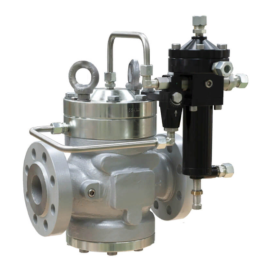
5.2 - PHYSICAL CHARACTERISTICS OF THE EQUIPMENT 5.2.1 - APERFLUX 851 Fig. 5.12. APERFLUX 851 physical characteristics APERFLUX 851 overall dimensions Nominal diameter [mm] Size [inches] 1” 2” 3” 4” 6” 8” 10” S - Ansi 150/PN 16 S - Ansi 300 S - Ansi 600 Ø... - Page 57 Weight [kgf] Ansi 150/PN 16 Ansi 300 Ansi 600 Tab. 5.28. HIGH PRESSURE REGULATOR TRANSPORT AND HANDLING REV. 00 Use, maintenance and warning manual...
-
Page 58: Aperflux 851 + Db/851
5.2.2 - APERFLUX 851 + DB/851 Fig. 5.13. APERFLUX 851 + DB/851 physical characteristics HIGH PRESSURE REGULATOR TRANSPORT AND HANDLING REV. 00 Use, maintenance and warning manual... - Page 59 APERFLUX 851 + DB/851 overall dimensions Nominal diameter [mm] Size [inches] 1” 2” 3” 4” 6” 8” 10” S - Ansi 150/PN 16 S - Ansi 300 S - Ansi 600 Ø 1025 1045 1085 1396 1175 1215 1081 1332...
-
Page 60: Aperflux 851 + Pm/819
5.2.3 - APERFLUX 851 + PM/819 Fig. 5.14. APERFLUX 851 + PM/819 physical characteristics HIGH PRESSURE REGULATOR TRANSPORT AND HANDLING REV. 00 Use, maintenance and warning manual... - Page 61 APERFLUX 851 + PM/819 overall dimensions Nominal diameter [mm] Size [inches] 1” 2” 3” 4” 6” 8” 10” S - Ansi 150/PN 16 S - Ansi 300 S - Ansi 600 Ø 1070 1205 1380 Connecting pneumatic Øe 10mm x Øi 8mm pipes Tab.
-
Page 62: Aperflux 851 + Sb /82 Or + Hb/97
5.2.4 - APERFLUX 851 + SB /82 OR + HB/97 Fig. 5.15. APERFLUX 851 + SB/82 OR + HB/97 physical characteristics HIGH PRESSURE REGULATOR TRANSPORT AND HANDLING REV. 00 Use, maintenance and warning manual... - Page 63 APERFLUX 851 + SB/82 OR + HB/97 overall dimensions Nominal diameter [mm] Size [inches] 1” 2” 3” 4” 6” 8” 10” S - Ansi 150/PN 16 S - Ansi 300 S - Ansi 600 Ø C WITH SB/82 C WITH HB/97...
-
Page 64: Aperflux 851 + Db/851 + Pm/819
5.2.5 - APERFLUX 851 + DB/851 + PM/819 Fig. 5.16. APERFLUX 851 + DB/851 + PM/819 physical characteristics HIGH PRESSURE REGULATOR TRANSPORT AND HANDLING REV. 00 Use, maintenance and warning manual... - Page 65 APERFLUX 851 + DB/851 + PM/819 overall dimensions Nominal diameter [mm] Size [inches] 1” 2” 3” 4” 6” 8” 10” S - Ansi 150/PN 16 S - Ansi 300 S - Ansi 600 Ø 1025 1045 1085 1155 1435 1856...
- Page 66 5.2.6 - APERFLUX 851 + DB/851 + SB/82 OR + HB/97 Fig. 5.17. Physical characteristics APERFLUX 851 + DB/82 + SB/82 OR + HB/97 HIGH PRESSURE REGULATOR TRANSPORT AND HANDLING REV. 00 Use, maintenance and warning manual...
- Page 67 Footprint and dimensionsAPERFLUX 851 +DB/82 + SB/82 OR + HB/97 Nominal diameter [mm] Size [inches] 1” 2” 3” 4” 6” 8” 10” S - Ansi 150/PN 16 S - Ansi 300 S - Ansi 600 Ø 1025 1045 1085 C WITH SB/82 C WITH HB/97 D WITH SB/82 D WITH HB/97...
-
Page 68: Equipment Anchoring And Lifting Method
5.3 - EQUIPMENT ANCHORING AND LIFTING METHOD HAZARD! Before moving the equipment, make sure that the capacity of the lifting equipment is suitable for the load. WARNING! Unloading, transport and handling activities must be carried out by operators qualified and specially trained: •... -
Page 69: Forklift Handling Method
5.3.1 - FORKLIFT HANDLING METHOD HAZARD! Prohibitions: • Do not transit under suspended loads; • Do not move the load overhead of the personnel operating in the site/plant area. WARNING! • Do not use forklifts to carry people; • Do not use forklifts to lift people. NOTE! Packaging must always be handled in a vertical position Proceed as follows:... - Page 70 Step Action Image Sollevare lentamente il carico di qualche decina di centimetri e veri carne la stabilità facendo attenzio- Inclinare il montante all’indietro (verso il posto guida) per avvantaggiare il momento ribaltante e Adeguare la velocità d ne che il baricentro del carico sia posizionato al centro delle forche di sollevamento. garantire una maggiore stabilità...
-
Page 71: Crane Handling Method
5.3.2 - CRANE HANDLING METHOD WARNING! CE-marked chains, ropes and eyebolts must be used. Do not use chains connected to each other by bolts. Always check that: • the safety catch of the hook returns to the initial position; • the ropes are in excellent condition and have an adequate section. -
Page 72: Packaging Removal
• do not install the equipment; • contact PIETRO FIORENTINI S.p.A. and specify the details provided on the equipment nameplate. 5.4.1 - PACKAGING DISPOSAL NOTE! Sort the various materials making up the packaging and dispose of them in compliance with the regula- tions in force in the country of installation. -
Page 73: Storage And Environmental Conditions
To replace the rubber parts of the equipment, please refer to chapter 9 “Maintenance and functional checks”. NOTE! PIETRO FIORENTINI S.p.A. recommends checking the condition of rubber parts in case of downtime or storage of more than 3 years. HIGH PRESSURE REGULATOR TRANSPORT AND HANDLING REV. - Page 74 HIGH PRESSURE REGULATOR TRANSPORT AND HANDLING REV. 00 Use, maintenance and warning manual...
-
Page 75: Installation
6 - INSTALLATION 6.1 - INSTALLATION PRE-REQUISITES 6.1.1 - ENVIRONMENTAL CONDITIONS ALLOWED WARNING! To safely use the equipment, adhere to the environmental conditions allowed and to the data provided on the nameplate of the regulator and any accessories (refer to paragraph 2.7 “Nameplates applied”). The installation site must be suitable for the safe use of the equipment. -
Page 76: Checks Before Installation
6.1.2 - CHECKS BEFORE INSTALLATION The equipment does not require any further safety device upstream to be protected against any overpressure with respect to its PS admissible pressure when, for the upstream reduction station, the maximum incidental downstream pressure is: MIPd ≤... -
Page 77: Specific Safety Instructions For The Installation Step
6.2 - SPECIFIC SAFETY INSTRUCTIONS FOR THE INSTALLATION STEP WARNING! Before proceeding with installation, make sure that the upstream and downstream valves installed on the line are closed. WARNING! Installation may also take place in areas where there is a risk of explosion, and this implies that all neces- sary prevention and protection measures must be taken. -
Page 78: General Information On Connections
6.3 - GENERAL INFORMATION ON CONNECTIONS The equipment must be installed in the line with the arrow on the body pointing in the gas flow direction. For installation in line as well as in a square pattern, the following must be on hand: Pos. -
Page 79: Regulator Installation Positions
NOTE! When used in gas pressure reduction stations, the device must be installed at least according to the re- quirements of standards UNI EN 12186:2014 or UNI EN 12279:2007. Equipment vents must be ducted in accordance with UNI EN 12186:2014 or UNI EN 12279:2007 or the standards in force at the place of installation of the equipment. -
Page 80: Installation Procedures
6.5 - INSTALLATION PROCEDURES 6.5.1 - EQUIPMENT INSTALLATION PROCEDURE To install the equipment in line and in a square pattern, proceed as follows: Step Action Place the equipment in the section of the line designated for it. Place the gaskets between the line flange and the regulator flange. Insert the bolts into the appropriate holes of the connecting flanges. - Page 81 To calculate the flow rate, use the following formula: 1 − 0,002 = 345,92 V = gas velocity in m/sec Q = gas flow rate Stm³/h DN = nominal diameter of the regulator in mm Pd = regulator outlet pressure in barg NOTE! All on-site pneumatic connections must have pipes with a minimum internal diameter of 8 mm To prevent the sensing line pipes from collecting impurities and condensation, it is necessary that:...
-
Page 82: Post-Installation And Pre-Commissioning Checks
If there is a sensing line, provide equipment connections as shown below: • 1 and 2 to the discharge outlet of the control head of the PM/819 monitor, if any; • 3 and 4 to the pilot sensing lines; • 5 and 6 to the sensing lines of the accelerator of the slam-shut device, if any. -
Page 83: Commissioning/Maintenance Equipment
7 - COMMISSIONING/MAINTENANCE EQUIPMENT 7.1 - LIST OF EQUIPMENT Commissioning/maintenance equipment • Mechanical maintenance technician; • Electrical maintenance technician; Operator qualification • Installer; • User’s technician. WARNING! The PPE listed in this table is related to the risk associated with the equipment. PPE required For the PPE required to protect against risks associated with the workplace, installation or operating conditions, please refer to:... -
Page 84: Equipment Needed For The Different Configurations
Ref. Equipment type Image T-handle hex socket wrench Phillips screwdriver Slotted screwdriver O-ring extraction tool Circlip pliers Fiorentini special key Fiorentini special key Fiorentini special tool Tab. 7.48. 7.2 - EQUIPMENT NEEDED FOR THE DIFFERENT CONFIGURATIONS Each table is distinguished by: Term Description Ref. - Page 85 24-27 24-27 24-27-32 24-27-32 24-27-32 24-27-32 32-36 Ø 5-6-10 5-6-14 5-6-17 5-6-17 4-5-6-17 6.5 x 100 Code 7999099 Tab. 7.50. Aperflux 851 + DB/851 Equipment Ref. Type 1” 2” 3” 4” 6” 8” 10” 14-16-17- 14-17-19- 14-17-19- 14-17-19- 14-17-19- 14-17-19-...
- Page 86 Aperflux 851 + SB/82 Equipment Ref. Type 1” 2” 3” 4” 6” 8” 10” 14-16-17- 14-17-19-- 14-17-19 14-17-19- 14-17-19- 14-17-19- 14-17-19- 29-24-27- 24-27 24-27 24-27-32 24-27-32 24-27-32 24-27-32 32-36 Ø 9-10-15-24 9-10-15-24 9-10-15-24 9-10-15-24 9-10-15-24 9-10-15-24 2-3-4-8 9-10-15-24 9-10-15-24 9-10-15-24 9-10-15-24 9-10-15-24...
-
Page 87: Commissioning
8 - COMMISSIONING 8.1 - GENERAL WARNINGS 8.1.1 - SAFETY REQUIREMENTS FOR COMMISSIONING HAZARD! During commissioning the risks associated with any discharges to the atmosphere of flammable or nox- ious gases must be evaluated. HAZARD! In case of installation on natural gas distribution networks, one should consider the risk of explosive mix- tures (gas/air) forming inside the piping, if the line is not subjected to inertisation. -
Page 88: Preliminary Procedures For Commissioning
8.2 - PRELIMINARY PROCEDURES FOR COMMISSIONING HAZARD! Before commissioning the equipment, it must be ensured that any source of explosion has been eliminat- ed if there is such a danger. WARNING! Before commissioning, you need to make sure that the characteristics of the equipment are suitable for the conditions of use. -
Page 89: Proper Commissioning Check
To properly calibrate all the accessories in the equipment, refer to the table below where, starting from the calibration of the regulator, all relevant values are defined: Calibration of a line consisting of: Aperflux 851 + incorporated monitor PM/819 or SB/82 slam-shut valve or HB/97 + LINE OFF 2.0/Pressure switch... -
Page 90: Commissioning The Regulator
8.5 - COMMISSIONING THE REGULATOR In the application consisting of two pressure adjusting lines, it is advisable to commission one line at a time, starting with the line with the lowest set point. The set point value is mentioned on the test certificate enclosed with each piece of equipment. Fig. - Page 91 Step Action Open the air vent valve (6). Completely unscrew the fixing nut of the pilot screw (3). Open the screw of the AR100 lamination valve (2) to a value between 3 and 5. Open the inlet shut-off valve V1 very slowly. NOTE! Check the pressure by referring to the pressure gauge (4) located upstream.
-
Page 92: Procedure For Commissioning The Aperflux 851 Regulator With Pm/819 Built-In Monitor
8.6 - PROCEDURE FOR COMMISSIONING THE APERFLUX 851 REGULATOR WITH PM/819 BUILT-IN MONITOR Fig. 8.26. Procedure for commissioning the regulator with PM/819 built-in monitor Step Action Partially open the drain cock (6). Completely unscrew the fixing nut of the pilot screw (positions 3 and 10). - Page 93 Step Action Make sure that the PM/819 monitor (8) is fully open (100%) by checking the position of the stroke indicator rod. NOTE! Check the pressure referring to the pressure gauge (5) located upstream. Close the drain cock (6) and check that the downstream pressure, after an increase phase, does not exceed the closing pressure value (refer to the SG value specified with reference to the calibration value/set point).
-
Page 94: Procedure For Commissioning The Aperflux 851 Regulator With Pm/819 Built-In Monitor And M/A Accelerator
8.7 - PROCEDURE FOR COMMISSIONING THE APERFLUX 851 REGULATOR WITH PM/819 BUILT-IN MONITOR AND M/A ACCELERATOR Fig. 8.27. Procedure for commissioning the regulator with PM/819 built-in monitor and M/A accelerator Step Action Partially open the drain cock (6). Completely unscrew the fixing nut of the screw of the pilots (positions 3 and 10) and of the M/A accelerator (12). - Page 95 Step Action Turn the monitor pilot adjustment screw (10) anticlockwise to decrease the downstream pressure value up to the selected working value of the monitor, making sure that the accelerator valve (12) has stopped the gas discharge; then lock the pilot screw 10 with the appropriate nut 9 (fig. 21). NOTE! Check the pressure referring to the pressure gauge (5) located upstream.
-
Page 96: Procedure For Commissioning The Aperflux 851 Regulator With Sb/82 Built-In Slam-Shut Valve
8.8 - PROCEDURE FOR COMMISSIONING THE APERFLUX 851 REGULATOR WITH SB/82 BUILT-IN SLAM-SHUT VALVE SB/82 8.8.1 - CHECKING THE SLAM-SHUT VALVE FOR PROPER SEALING WHEN CLOSING Fig. 8.28. Sealing of the SB/82 slam-shut valve when closing Step Action Check that the slam-shut valve is in the closed position. -
Page 97: Pressure Switches Calibration Procedure 102M/102Mh - 105M/105Mh
8.8.2 - PRESSURE SWITCHES CALIBRATION PROCEDURE 102M/102MH - 105M/105MH Fig. 8.29. Pressure switches calibration Models 102M/102MH - 105M/105MH SPRING CALIBRATION FOR MAXIMUM PRESSURE TRIP Step Action In order to check for proper tripping calibration, increase the downstream pressure until the slam-shut device trips by acting on the pilot adjustment screw (3). - Page 98 SPRING CALIBRATION FOR MINIMUM PRESSURE TRIP (IF ANY) Step Action Open the vent to the atmosphere (6) and keep it open for the next steps. Use the pilot adjustment screw (3) to decrease the downstream pressure to the minimum pressure required for the slam-shut device to trip.
-
Page 99: Procedure For Commissioning The Aperflux 851 Regulator With Hb/97 Built-In Slam-Shut Valve
8.9 - PROCEDURE FOR COMMISSIONING THE APERFLUX 851 REGULATOR WITH HB/97 BUILT-IN SLAM-SHUT VALVE HB/97 8.9.1 - CHECKING THE BUILT-IN SLAM-SHUT VALVE FOR SEALING WHEN CLOSING Fig. 8.30. Sealing of the HB/97 slam-shut valve when closing Step Action Check that the built-in slam-shut valve is in the closed position. -
Page 100: Line Off 2.0 Commissioning And Calibration Procedure For Hb/97 Built-In Slam-Shut Valve
8.9.2 - LINE OFF 2.0 COMMISSIONING AND CALIBRATION PROCEDURE FOR HB/97 BUILT-IN SLAM-SHUT VALVE 7.5 7.3 Fig. 8.31. LINE OFF 2.0 commissioning and calibration for the HB/97 built-in slam-shut valve HIGH PRESSURE REGULATOR COMMISSIONING REV. 00 Use, maintenance and warning manual... -
Page 101: Calibration Of The Pressure Switch For Line Off 2.0
Step Action Completely unscrew the fixing nut of the pilot adjustment screw (3). Fully release the pilot spring (3) by turning the adjustment screw anticlockwise. Press and hold the button of the bypass device HP2/2 (7.1) to: • bring the upstream pressure to the LINE-OFF 2.0 power supply unit (7); •... -
Page 102: Device Calibration
8.11 - DEVICE CALIBRATION 8.11.1 - 200 AND 300 SERIES PILOTS Fig. 8.32. 200 and 300 series pilots Turn the adjustment screw (10): • anticlockwise to decrease the adjusted pressure; • clockwise to increase the adjusted pressure. HIGH PRESSURE REGULATOR COMMISSIONING REV. -
Page 103: Pressure Switches Models 102M/102Mh - 105M/105Mh
8.11.2 - PRESSURE SWITCHES MODELS 102M/102MH - 105M/105MH Fig. 8.33. Pressure switches models 102 - 105 Turn the ring nut of max (13): • anticlockwise to decrease the slim-shut device tripping pressure; • clockwise to increase the slim-shut device tripping pressure. Turn the min ring nut (15): •... - Page 104 HIGH PRESSURE REGULATOR COMMISSIONING REV. 00 Use, maintenance and warning manual...
-
Page 105: Maintenance And Functional Checks
WARNING! In case of doubt, do not perform any work. Contact PIETRO FIORENTINI S.p.A. for the necessary clarifica- tions. The management and/or use of the equipment includes interventions that are necessary as a result of normal use such as: •... - Page 106 Before beginning disassembly of the equipment, make sure that: • the spare parts and parts used in replacements have adequate requirements to ensure the original performance of the equipment. Use recommended original spare parts; • the operator has the necessary equipment (see chapter 7 “Equipment for commissioning/maintenance”). NOTE! The recommended spare parts are unambiguously identified with tags indicating: •...
-
Page 107: Periodically Checking And Inspecting The Equipment For Proper Operation
9.2 - PERIODICALLY CHECKING AND INSPECTING THE EQUIPMENT FOR PROPER OPERATION Periodic checks and inspections Operator qualification Mechanical maintenance technician WARNING! The PPE listed in this table is related to the risk associated with the equipment. PPE required For the PPE required to protect against risks associated with the workplace, installation or operating conditions, please refer to: •... -
Page 108: Routine Maintenance
9.3 - ROUTINE MAINTENANCE 9.3.1 - GENERAL SAFETY WARNINGS HAZARD! • Put the equipment in a safe condition (close the downstream and then the upstream shut-off valve, drain the equipment completely and lastly drain the line); • Ensure that the pressure upstream and downstream of the equipment is “0”. NOTE! Before installing new sealing elements (o-rings, diaphragm, etc.), they must be checked for integrity. -
Page 109: Replacement Frequency For Components Subject To Wear
9.3.2 - REPLACEMENT FREQUENCY FOR COMPONENTS SUBJECT TO WEAR NOTE! The following provisions shall apply to equipment components only. The non-metallic parts of the equipment concerned are divided into the following two categories: Preventive maintenance work Covers parts subject to wear and/or abrasion, where: •... - Page 110 Minimum Category Part description Evaluation criterion replacement frequency Shut-off valves Yearly Lubricating parts Other equipment Yearly Filter elements Filters needed Tab. 9.70. HIGH PRESSURE REGULATOR MAINTENANCE AND FUNCTIONAL CHECKS REV. 00 Use, maintenance and warning manual...
-
Page 111: Routine Maintenance Procedures
9.4 - ROUTINE MAINTENANCE PROCEDURES Routine maintenance Operator qualification Mechanical maintenance technician WARNING! The PPE listed in this table is related to the risk associated with the equipment. PPE required For the PPE required to protect against risks associated with the workplace, installation or operating conditions, please refer to: •... -
Page 112: Tightening Torques Aperflux 851
9.4.1 - TIGHTENING TORQUES APERFLUX 851 1”÷2” 3” 6”÷8” 4” 10” Fig. 9.34. Tightening torques APERFLUX 851 HIGH PRESSURE REGULATOR MAINTENANCE AND FUNCTIONAL CHECKS REV. 00 Use, maintenance and warning manual... - Page 113 APERFLUX 851 DN 1” Pos. Description Torque (nm) Torque (ft - lb) Screw M10X80 UNI 5939 Screw M10X30 UNI 5739 Screw M6X12 UNI 5931 Nut M12 UNI 5588 Nut M10 UNI 5588 Tab. 9.72. APERFLUX 851 DN 2” Pos. Description...
- Page 114 1”÷2” 3” 6”÷8” 4” 10” Tightening torques APERFLUX 851 HIGH PRESSURE REGULATOR MAINTENANCE AND FUNCTIONAL CHECKS REV. 00 Use, maintenance and warning manual...
- Page 115 APERFLUX 851 DN 6” Pos. Description Torque (nm) Torque (ft - lb) Fitting Aperflux Screw M20X60 UNI 5737 Screw M20X50 UNI 5931 Screw M6X16 UNI 5931 Screw M6X20 UNI 5931 Screw M6X25 UNI 5931 Nut M16 UNI 5588 Nut M20 UNI 5587 Tab.
- Page 116 9.4.1.1 - TIGHTENING TORQUES FOR PILOTS SERIES 300 24.1 Fig. 9.35. Tightening torques for 302/A pilot PILOT 302/A Pos. Description Torque (nm) Torque (ft - lb) Nut M16X1 Screw M8X30 UNI 5931 AISI Screw M8X25 UNI 5931 AISI 24.1 Screw M8X30 UNI 5931 AISI Nut M16X1.5 Nut M18X1.5 Nut M20X1...
- Page 117 304/A-305/A 307/A Fig. 9.36. Tightening torques for 304/A-305/A-307/A pilots PILOTS 304/A-305/A-307/A Pos. Description Torque (nm) Torque (ft - lb) Nut M16X1 Nut M16X1.5 Screw M8X30 UNI 5931 AISI Nut M16X1.5 Nut M18X1.5 Tab. 9.80. HIGH PRESSURE REGULATOR MAINTENANCE AND FUNCTIONAL CHECKS REV.
- Page 118 9.4.1.2 - TIGHTENING TORQUES FOR LAMINATION VALVE AR100 Fig. 9.37. Tightening torques for lamination valve AR100 LAMINATION VALVE AR100 Pos. Description Torque (nm) Torque (ft - lb) Cap M20X1.5 Screw M8 AISI Tab. 9.81. HIGH PRESSURE REGULATOR MAINTENANCE AND FUNCTIONAL CHECKS REV.
- Page 119 HIGH PRESSURE REGULATOR MAINTENANCE AND FUNCTIONAL CHECKS REV. 00 Use, maintenance and warning manual...
- Page 120 9.4.1.3 - TIGHTENING TORQUES APERFLUX 851 + SILENCER DB/851 Fig. 9.38. Tightening torques APERFLUX 851 + Silencer DB/851 HIGH PRESSURE REGULATOR MAINTENANCE AND FUNCTIONAL CHECKS REV. 00 Use, maintenance and warning manual...
- Page 121 APERFLUX 851 DN 1” + DB/851 Pos. Description Torque (nm) Torque (ft - lb) Screw M10X30 UNI 5739 Screw M6X12 UNI 5931 Nut M12 UNI 5588 Screw M10X35 UNI 5931 Nut M14 UNI 5588 Screw M10X45 UNI 5939 Tab. 9.82.
- Page 122 Tightening torques APERFLUX 851 + Silencer DB/851 HIGH PRESSURE REGULATOR MAINTENANCE AND FUNCTIONAL CHECKS REV. 00 Use, maintenance and warning manual...
- Page 123 APERFLUX 851 DN 6” + DB/851 Pos. Description Torque (nm) Torque (ft - lb) Fitting Aperflux Screw M20X60 UNI 5737 Screw M6X16 UNI 5931 Screw M6X20 UNI 5931 Nut M16 UNI 5588 Nut M22 UNI 5588 Screw M20X70 UNI 5931 Screw M20X60 UNI 5737 Tab.
- Page 124 9.4.1.4 - TIGHTENING TORQUES FOR PM/819 BUILT-IN MONITOR Fig. 9.39. Tightening torques for PM/819 built-in monitor PM/819 DN 1” Pos. Description Torque (nm) Torque (ft - lb) Nut M12 M12 balancing piston guide Screw M16X70 UNI 5737 Screw M10X35 5739 Screw M6X14 UNI 5931 Screw M6X12 UNI 5931 Screw M10X30 UNI 5739...
- Page 125 PM/819 DN 2” Pos. Description Torque (nm) Torque (ft - lb) Nut M12 M12 balancing piston guide Screw M16X70 UNI 5737 Screw M10X35 5739 Screw M6X14 UNI 5931 Screw M6X12 UNI 5931 Screw M12X35 UNI 5739 Tab. 9.90. PM/819 DN 3” Pos.
- Page 126 Tightening torques for PM/819 built-in monitor HIGH PRESSURE REGULATOR MAINTENANCE AND FUNCTIONAL CHECKS REV. 00 Use, maintenance and warning manual...
- Page 127 PM/819 DN 6” Pos. Description Torque (nm) Torque (ft - lb) Nut M24 M18 balancing piston guide Screw M22X120 UNI 5737 Screw M14X50 UNI 5737 Screw M6X16 UNI 5931 Screw M6X16 UNI 5931 Screw M20X60 UNI 5737 Nut M18 UNI 5589 Tab.
- Page 128 9.4.1.5 - TIGHTENING TORQUES FOR PILOTS SERIES 200 204/A-205/A 207/A Fig. 9.40. Tightening torques for 204/A-205/A-207/A pilots PILOTS 204/A-205/A Pos. Description Torque (nm) Torque (ft - lb) Nut M16X1 Screw M8X30 UNI 5931 AISI Nut M16X1.5 Nut M18X1.5 Tab. 9.96. PILOT 207/A Pos.
- Page 129 9.4.1.6 - TIGHTENING TORQUES FOR PRE-REGULATORS R14/A Fig. 9.41. Tightening torques for pre-regulator R14/A PRE-REGULATOR R14/A Pos. Description Torque (nm) Torque (ft - lb) Nut M8X30 UNI 5931 AISI Nut M8 UNI 5588 Tab. 9.98. HIGH PRESSURE REGULATOR MAINTENANCE AND FUNCTIONAL CHECKS REV.
- Page 130 9.4.1.7 - TIGHTENING TORQUES FOR SB/82 BUILT-IN SLAM-SHUT VALVE Fig. 9.42. Tightening torques for SB/82 DN 1” built-in slam-shut valve SB/82 DN 1” Pos. Description Torque (nm) Torque (ft - lb) Safety valve screw M10 Screw M6X12 UNI 5931 Screw M6X20 UNI 5931 Screw M6X20 UNI 5931 Screw M12X45 UNI 5931 Screw M10X25 UNI 5931...
- Page 131 Fig. 9.43. Tightening torques for SB/82 DN 2” built-in slam-shut valve SB/82 DN 2” Pos. Description Torque (nm) Torque (ft - lb) Safety valve screw M10 Screw M6X12 UNI 5931 Screw M6X20 UNI 5931 Screw M6X20 UNI 5931 Screw M6X20 UNI 5931 Screw M12X45 UNI 5931 Tab.
- Page 132 Fig. 9.44. Tightening torques for SB/82 DN 3”-DN 4” built-in slam-shut valve SB/82 DN 3” Pos. Description Torque (nm) Torque (ft - lb) Safety valve screw M10 Screw M12X40 UNI 5739 Screw M6X12 UNI 5931 Screw M6X20 UNI 5931 Screw M6X20 UNI 5931 Screw M6X20 UNI 5931 Nut M12 UNI 5588 Tab.
- Page 133 Fig. 9.45. Tightening torques for SB/82 DN 6”-DN 8” built-in slam-shut valve SB/82 DN 6” Pos. Description Torque (nm) Torque (ft - lb) Safety valve screw Screw M14X50 UNI 5737 Screw M6X16 UNI 5931 Screw M6X10 UNI 5931 Screw M8X25 UNI 5931 Screw M6X40 UNI 5931 Screw M6X20 UNI 5931 Nut M14 UNI 5588...
- Page 134 Fig. 9.46. Tightening torques for SB/82 DN 10” built-in slam-shut valve SB/82 DN 10” Pos. Description Torque (nm) Torque (ft - lb) Screw M16X90 UNI 5737 Screw M6X16 UNI 5931 Nut M20 UNI 5589 Screw M6X20 UNI 5931 Screw M8X25 UNI 5931 Screw M6X35 UNI 5931 Screw M6X20 UNI 5931 Tab.
- Page 135 HIGH PRESSURE REGULATOR MAINTENANCE AND FUNCTIONAL CHECKS REV. 00 Use, maintenance and warning manual...
- Page 136 9.4.1.8 - TIGHTENING TORQUES FOR PRESSURE SWITCHES MODELS 102M/102MH - 105M/105MH MOD. 102M/102MH MOD. 104M/104MH MOD. 103M/103MH MOD. 105M/105MH Fig. 9.47. Tightening torques for pressure switches models 102M/102MH - 105M/105MH HIGH PRESSURE REGULATOR MAINTENANCE AND FUNCTIONAL CHECKS REV. 00 Use, maintenance and warning manual...
- Page 137 MOD. 102M/102MH Pos. Description Torque (nm) Torque (ft - lb) SCREW M4X10 UNI 5931 2.21 SCREW M5X10 UNI 5933 3.68 SCREW M6X16 UNI 5931 7.37 NUT M6 UNI 5588 7.37 SCREW M5X15 UNI 8112 3.68 SCREW M6X25 UNI 5931 11.80 NUT M20X1 5.90 SCREW M5X16 UNI 5931...
- Page 138 9.4.1.9 - TIGHTENING TORQUES FOR HB/97 BUILT-IN SLAM-SHUT VALVE WITH LINE-OFF DN 4” DN 6” - 10” Fig. 9.48. Tightening torques for HB/97 built-in slam-shut valve with LINE OFF 4” 6”÷10” HB/97 DN 4” Pos. Description Torque (nm) Torque (ft - lb) Locking nut M12X1.25 Balancing piston guide M12X1.25 Screw M10X40 UNI 5737...
- Page 139 HB/97 DN 8” Pos. Description Torque (nm) Torque (ft - lb) Locking nut M24X1.5 Balancing piston guide M18X1.5 Screw M14X50 UNI 5737 Nut M18X1.5 UNI 5589 Nut M16 UNI 5588 Screw M8X20 UNI 5931 Screw M6X25 UNI 5931 Screw M6X16 UNI 5931 Tab.
- Page 140 9.4.1.10 - TIGHTENING TORQUES FOR HP2/2 BYPASS DEVICE Fig. 9.49. Tightening torques for HP2/2 bypass device HP/22 Pos. Description Torque (nm) Torque (ft - lb) Screw M8X20 UNI 5931 Screw M8X45 UNI 5931 Tab. 9.113. HIGH PRESSURE REGULATOR MAINTENANCE AND FUNCTIONAL CHECKS REV.
- Page 141 9.4.1.11 - TIGHTENING TORQUES FOR R44/SS REGULATOR 24.1 Fig. 9.50. Tightening torques for R44/SS regulator R44/SS Pos. Description Torque (nm) Torque (ft - lb) Nut M16X1 Screw M8X110 UNI 5931 24.1 Screw M8X70 UNI 5931 Nut M16X1.5 Nut M18X1.5 Tab. 9.114. HIGH PRESSURE REGULATOR MAINTENANCE AND FUNCTIONAL CHECKS REV.
- Page 142 HIGH PRESSURE REGULATOR MAINTENANCE AND FUNCTIONAL CHECKS REV. 00 Use, maintenance and warning manual...
-
Page 143: Replacing Elements Subject To Wear And Abrasion
9.4.2 - REPLACING ELEMENTS SUBJECT TO WEAR AND ABRASION 9.4.2.1 - INITIAL OPERATIONS ATTENTION! Before carrying out any work, it is important to ensure that the line on which the regulator is installed has been shut off upstream and downstream, and discharged. ATTENTION! During assembly, make sure to tighten the screws as per the tables (tightening torques), according to the size for which maintenance is being carried out. -
Page 144: Regulator Aperflux 851 Dn 1" - 3
9.4.3 - REGULATOR APERFLUX 851 DN 1” - 3” Fig. 9.52. Regulator APERFLUX 851 DN 1” - 3” HIGH PRESSURE REGULATOR MAINTENANCE AND FUNCTIONAL CHECKS REV. 00 Use, maintenance and warning manual... - Page 145 Step Action Loosen the fixing screws (24). Remove the upper lid (4). Remove the spring (45). Take out the diaphragm unit (14, 15, 20, 30). Loosen and remove the nut (30) Remove the diaphragm protection disc (15). Remove and replace the diaphragm (20) from the screw (14), taking care to lubricate the lanyard with synthetic grease.
- Page 146 Regulator APERFLUX 851 DN 1” - 3” HIGH PRESSURE REGULATOR MAINTENANCE AND FUNCTIONAL CHECKS REV. 00 Use, maintenance and warning manual...
- Page 147 Step Action APPLICABLE TO DN 3” ONLY Remove the O-ring (37) from the intermediate flange (2) and replace it, taking care to lubricate it with synthetic grease. NOTE! Before inserting the replacement O-ring, clean the retaining slots with a cleaning solution. Remove the O-ring (37) from the blind flange (5) and replace it, taking care to lubricate it with synthetic grease.
- Page 148 Regulator APERFLUX 851 DN 1” - 3” HIGH PRESSURE REGULATOR MAINTENANCE AND FUNCTIONAL CHECKS REV. 00 Use, maintenance and warning manual...
- Page 149 Step Action Insert and fix the screws (25) according to the following tightening torques: • DN 1” > tab. 9.72; • DN 2” > tab. 9.73; • DN 3” > tab. 9.74. NOTE! Screw in according to the cross diagram in paragraph 9.4.2.2. Fit the valve seat (13) into the intermediate flange (3) from the top downwards.
- Page 150 9.4.3.1 - REGULATOR APERFLUX 851 DN 4” - 8” DETAIL DN 4” Fig. 9.53. Regulator APERFLUX 851 DN 4” - 8” HIGH PRESSURE REGULATOR MAINTENANCE AND FUNCTIONAL CHECKS REV. 00 Use, maintenance and warning manual...
- Page 151 Step Action APPLICABLE TO DN 4” ONLY Loosen the eyebolt and the fixing screws (24). APPLICABLE TO DN 6” 8” ONLY Loosen the fixing nuts (31). Remove the upper lid (4). Remove the spring (45). Take out the diaphragm unit (14, 15, 20, 30). Loosen and remove the nut (30).
- Page 152 DETAIL DN 4” Regulator APERFLUX 851 DN 4” - 8” HIGH PRESSURE REGULATOR MAINTENANCE AND FUNCTIONAL CHECKS REV. 00 Use, maintenance and warning manual...
- Page 153 Step Action Remove the O-ring (38) from the intermediate flange (3) and replace it, taking care to lubricate it with synthetic grease. NOTE! Before inserting the replacement O-ring, clean the retaining slots with a cleaning solution. Unscrew and remove the screws (26). Remove the flange (2).
- Page 154 DETAIL DN 4” Regulator APERFLUX 851 DN 4” - 8” HIGH PRESSURE REGULATOR MAINTENANCE AND FUNCTIONAL CHECKS REV. 00 Use, maintenance and warning manual...
- Page 155 Step Action Insert and fix the screws (25) according to the following tightening torques: • DN 4” > tab. 9.75; • DN 6” > tab. 9.76; • DN 8” > tab. 9.77. NOTE! Tighten the screws according to the cross diagram in paragraph 9.4.2.2. Fit the flange (2).
- Page 156 DETAIL DN 4” Regulator APERFLUX 851 DN 4” - 8” HIGH PRESSURE REGULATOR MAINTENANCE AND FUNCTIONAL CHECKS REV. 00 Use, maintenance and warning manual...
- Page 157 Step Action Put the diaphragm unit (14, 15, 20, 30) in place and lubricate the retaining slots with synthetic grease. Fit the spring (45). Fit the upper lid (4). APPLICABLE TO DN 4” ONLY Insert and fix the screws (24) according to the following tightening torques: •...
- Page 158 9.4.3.2 - REGULATOR APERFLUX 851 DN 10” Fig. 9.54. Regulator APERFLUX 851 DN 10” HIGH PRESSURE REGULATOR MAINTENANCE AND FUNCTIONAL CHECKS REV. 00 Use, maintenance and warning manual...
- Page 159 Step Action Loosen and remove the fixing nuts (31). Remove the upper lid (4). Remove the springs (44, 45). Take out the diaphragm unit (14, 15, 20, 30). Loosen and remove the screws (30) Remove the diaphragm protection disc (15) Remove the diaphragm (20) from the support (14) Replace the diaphragm (20).
- Page 160 Regulator APERFLUX 851 DN 10” HIGH PRESSURE REGULATOR MAINTENANCE AND FUNCTIONAL CHECKS REV. 00 Use, maintenance and warning manual...
- Page 161 Step Action WARNING! Support the flange to prevent it from falling Remove the blind flange (5). Remove the O-ring (37) from the blind flange (5) and replace it, taking care to lubricate it with synthetic grease. NOTE! Before inserting the replacement O-ring, clean the retaining slots with a cleaning solution. WARNING! Support the sleeve during the next steps to prevent it from falling.
- Page 162 Regulator APERFLUX 851 DN 10” HIGH PRESSURE REGULATOR MAINTENANCE AND FUNCTIONAL CHECKS REV. 00 Use, maintenance and warning manual...
- Page 163 Step Action Screw in and fix the fitting (90). Screw and fix the supply fitting (35), ensuring its tightness in the thread. NOTE! For the next action, carefully support the flange to prevent it from falling. Fit the blind flange (5). Insert and fix the screws (25) according to the following tightening torque: •...
-
Page 164: Maintenance Of The 300/A Series Pilot + Ar100 Lamination Valve
9.4.4 - MAINTENANCE OF THE 300/A SERIES PILOT + AR100 LAMINATION VALVE 9.4.4.1 - 300/A SERIES PILOT DISCONNECTION DOWNSTREAM SENSING ELEMENT TO REDUCER GAS LEAK UPSTREAM SENSING ELEMENT VENT Fig. 9.55. 300/A series pilot HIGH PRESSURE REGULATOR MAINTENANCE AND FUNCTIONAL CHECKS REV. - Page 165 To disconnect the pilot, proceed as follows: Step Action Disconnect the sensing lines between the 300/A pilot and the regulator by acting on the fittings (1, 2, 3, 4). Unscrew and remove the fixing screw to remove the pilot from the regulator. Unscrew and remove the screw (5) to separate the AR100 lamination valve from the pilot.
- Page 166 9.4.4.2 - PILOT 302/A A ASSEMBLY (DIAPHRAGM) B ASSEMBLY (VALVE) 26.1 24.1 C ASSEMBLY (PLUG) Fig. 9.56. Pilot 302/A HIGH PRESSURE REGULATOR MAINTENANCE AND FUNCTIONAL CHECKS REV. 00 Use, maintenance and warning manual...
- Page 167 Step Action Loosen the nut (9). Completely release the spring (22) by turning the adjustment screw (10). Remove the adjustment screw (10) together with the cap (9). Remove the cap (8). Remove the O-ring (35) from the cap (8) and replace it, taking care to lubricate it with synthetic grease. NOTE! Before inserting the replacement O-ring, clean the retaining slots with a cleaning solution.
- Page 168 A ASSEMBLY (DIAPHRAGM) B ASSEMBLY (VALVE) 26.1 24.1 C ASSEMBLY (PLUG) Pilot 302/A HIGH PRESSURE REGULATOR MAINTENANCE AND FUNCTIONAL CHECKS REV. 00 Use, maintenance and warning manual...
- Page 169 Step Action Remove the bush (41) Remove the balancing piston (42). Take out the piston guide (40). Remove the O-ring (51) from the piston guide (40) and replace it, taking care to lubricate it with synthetic grease. NOTE! Before inserting the replacement O-ring, clean the retaining slots with a cleaning solution. Remove the O-ring (52) from the valve seat (3) and replace it, taking care to lubricate it with synthetic grease.
- Page 170 A ASSEMBLY (DIAPHRAGM) B ASSEMBLY (VALVE) 26.1 24.1 C ASSEMBLY (PLUG) Pilot 302/A HIGH PRESSURE REGULATOR MAINTENANCE AND FUNCTIONAL CHECKS REV. 00 Use, maintenance and warning manual...
- Page 171 Step Action Remove and replace the lower diaphragm (16), taking care to lubricate the lanyards with synthetic grease. NOTE! Before inserting the replacement diaphragm, clean the retaining slots with a cleaning solution. Fit the protection disc (15). Fix the nut (25) according to the following tightening torque: •...
- Page 172 9.4.4.3 - PILOTS 304/A - 305/A A ASSEMBLY (PLUG) 26.1 B ASSEMBLY (VALVE) Fig. 9.57. Pilots 304/A - 305/A HIGH PRESSURE REGULATOR MAINTENANCE AND FUNCTIONAL CHECKS REV. 00 Use, maintenance and warning manual...
- Page 173 Step Action Loosen the nut (9). Completely release the spring (22) by turning the adjustment screw (10). Remove the adjustment screw (10) together with the cap (9). Unscrew and remove the cap (8). Remove the O-ring (35) from the cap (8) and replace it, taking care to lubricate it with synthetic grease. NOTE! Before inserting the replacement O-ring, clean the retaining slots with a cleaning solution.
- Page 174 A ASSEMBLY (PLUG) 26.1 26.1 B ASSEMBLY (VALVE) Pilots 304/A - 305/A Pilots 304/A - 305/A HIGH PRESSURE REGULATOR MAINTENANCE AND FUNCTIONAL CHECKS REV. 00 Use, maintenance and warning manual...
- Page 175 Step Action Insert the bush (41) into the pilot seat (3) so that the wider stop rests on the O-ring (51). Insert and fix the valve seat (38). NOTE! Take care not to damage the valve seat profile (38) and the O-ring (50) Remove assembly “A”...
- Page 176 A ASSEMBLY (PLUG) 26.1 B ASSEMBLY (VALVE) Pilots 304/A - 305/A HIGH PRESSURE REGULATOR MAINTENANCE AND FUNCTIONAL CHECKS REV. 00 Use, maintenance and warning manual...
- Page 177 Step Action Fit the spring (20). Fit the lid (1). Insert and fix the screws of the upper section (24) according to the following tightening torque: • Pilots 304-305 > tab. 9.80 Fit the sleeve (6) and the bracket (14). Insert and fix the screws of the lower section (24) according to the following tightening torque: •...
- Page 178 9.4.4.4 - PILOT 307/A A ASSEMBLY (PLUG) 26.1 B ASSEMBLY (VALVE) Fig. 9.58. Pilot 307/A HIGH PRESSURE REGULATOR MAINTENANCE AND FUNCTIONAL CHECKS REV. 00 Use, maintenance and warning manual...
- Page 179 Step Action Loosen the nut (9). Completely release the spring (22) by turning the adjustment screw (10). Remove the adjustment screw (10) together with the cap (9). Unscrew and remove the cap (8). Remove the O-ring (35) from the cap (8) and replace it, taking care to lubricate it with synthetic grease. NOTE! Before inserting the replacement O-ring, clean the retaining slots with a cleaning solution.
- Page 180 A ASSEMBLY (PLUG) 26.1 B ASSEMBLY (VALVE) Pilot 307/A HIGH PRESSURE REGULATOR MAINTENANCE AND FUNCTIONAL CHECKS REV. 00 Use, maintenance and warning manual...
- Page 181 Step Action Remove the O-ring (52) from the valve seat (3) and replace it, taking care to lubricate it with synthetic grease. NOTE! Before inserting the replacement O-ring, clean the retaining slots with a cleaning solution. Remove the O-rings (28, 29) from the valve seat (3) and replace them, taking care to lubricate them with syn- thetic grease.
- Page 182 A ASSEMBLY (PLUG) 26.1 B ASSEMBLY (VALVE) Pilot 307/A HIGH PRESSURE REGULATOR MAINTENANCE AND FUNCTIONAL CHECKS REV. 00 Use, maintenance and warning manual...
- Page 183 Step Action Insert and fix the screws of the upper section (24) according to the following tightening torque: • Pilots 307 > tab. 9.80 Fit the sleeve (6) and the bracket (14). Insert and fix the screws of the lower section (24) according to the following tightening torque: •...
- Page 184 9.4.4.6 - AR100 LAMINATION VALVE SEZ. A-A Fig. 9.59. AR100 lamination valve Step Action Unscrew and remove the locking screw (97). Remove the O-rings (96) from the AR100 lamination valve body (1) and replace them, taking care to lubricate them with synthetic grease. NOTE! Before inserting the replacement O-rings, clean the retaining slots with a cleaning solution.
- Page 185 Step Action Remove the O-rings (6, 7) from the cap (2) and replace them, taking care to lubricate them with synthetic grease. NOTE! Before inserting the replacement O-rings, clean the retaining slots with a cleaning solution. Remove and replace the filter (5). Fit and fix the cap (2) according to the following tightening torque: •...
-
Page 186: Db/851 Silencer Maintenance
9.4.5 - DB/851 SILENCER MAINTENANCE 9.4.5.1 - SILENCER DB/851 DN 1”- 3” Fig. 9.60. Silencer DB/851 DN 1”- 3” HIGH PRESSURE REGULATOR MAINTENANCE AND FUNCTIONAL CHECKS REV. 00 Use, maintenance and warning manual... - Page 187 Step Action Loosen the eyebolt (48) and the fixing screws (71). Remove the upper lid (4). Remove the spring (45). Take out the diaphragm unit (14, 15, 20, 30). Remove the diaphragm protection grid (17). Unscrew and remove the nut (68). Remove the upper flange (58) together with the valve seat (13).
- Page 188 Silencer DB/851 DN 1”- 3” HIGH PRESSURE REGULATOR MAINTENANCE AND FUNCTIONAL CHECKS REV. 00 Use, maintenance and warning manual...
- Page 189 Step Action Remove and replace the O-ring (37) from the blind flange (5) or from any built-in accessory (SB/82 slam-shut valve or PM/819 monitor), taking care to lubricate it with synthetic grease. NOTE! Before inserting the replacement O-ring, clean the retaining slots with a cleaning solution. Undo and remove the screws (27).
- Page 190 Silencer DB/851 DN 1”- 3” HIGH PRESSURE REGULATOR MAINTENANCE AND FUNCTIONAL CHECKS REV. 00 Use, maintenance and warning manual...
- Page 191 Tighten the screws according to the cross diagram in paragraph 9.4.2.2. Put the eyebolt (48) back in place. Tab. 9.127. NOTE! To replace the O-rings not mentioned in this procedure, refer to maintenance table “APERFLUX 851 1” 3”. WARNING! Ensure that all parts have been fitted correctly.
- Page 192 9.4.5.2 - SILENCER DB/851 DN 4”- 10” Fig. 9.61. Silencer DB/851 DN 4”- 10” HIGH PRESSURE REGULATOR MAINTENANCE AND FUNCTIONAL CHECKS REV. 00 Use, maintenance and warning manual...
- Page 193 Step Action APPLICABLE TO DN 4” ONLY Undo the screws (71), eyebolts (48), nut (73). APPLICABLE TO DN 6” - 10” ONLY Loosen the screws (71) and remove the washers (33). Remove the upper lid (4). APPLICABLE TO DN 4” - 8” Remove the spring (45).
- Page 194 Silencer DB/851 DN 4”- 10” HIGH PRESSURE REGULATOR MAINTENANCE AND FUNCTIONAL CHECKS REV. 00 Use, maintenance and warning manual...
- Page 195 Step Action Remove the O-ring (84) from the sleeve (63) and replace it, taking care to lubricate it with synthetic grease. NOTE! Before inserting the replacement O-ring, clean the retaining slots with a cleaning solution. Remove the internal basket (65). NOTE! To do so, use tool ref.
- Page 196 Silencer DB/851 DN 4”- 10” HIGH PRESSURE REGULATOR MAINTENANCE AND FUNCTIONAL CHECKS REV. 00 Use, maintenance and warning manual...
- Page 197 Step Action Remove the O-ring (39) from the valve seat (8) and replace it, taking care to lubricate it with synthetic grease. NOTE! Before inserting the replacement O-ring, clean the retaining slots with a cleaning solution. Clean the upper and lower support surfaces of the body (1) and the flanges (2, 5) as well as the contact sur- faces between the sleeve (63), the conical seat (8) and the body.
- Page 198 Silencer DB/851 DN 4”- 10” HIGH PRESSURE REGULATOR MAINTENANCE AND FUNCTIONAL CHECKS REV. 00 Use, maintenance and warning manual...
- Page 199 Step Action Insert and fix the screws (69) according to the following tightening torques: • DN 4” > tab 9.85; • DN 6” > tab. 9.86; • DN 8” > tab. 9.87; • DN 10” > tab. 9.88. NOTE! Tighten the screws according to the cross diagram in paragraph 9.4.2.2. Fit the lower anti-oil gasket (88).
- Page 200 Silencer DB/851 DN 4”- 10” HIGH PRESSURE REGULATOR MAINTENANCE AND FUNCTIONAL CHECKS REV. 00 Use, maintenance and warning manual...
- Page 201 Step Action Fit and fix the screws (28) according to the following tightening torques: • DN 4” > tab 9.85; • DN 6” > tab. 9.86; • DN 8” > tab. 9.87; • DN 10” > tab. 9.88. NOTE! Tighten the screws according to the cross diagram in paragraph 9.4.2.2. Fit the diaphragm protection grid (17).
-
Page 202: Pm/819 Built-In Monitor Operation
9.4.6 - PM/819 BUILT-IN MONITOR OPERATION 9.4.6.1 - BUILT-IN MONITOR PM/819 DN 1”- 2” Fig. 9.62. Built-in monitor PM/819 DN 1”- 2” HIGH PRESSURE REGULATOR MAINTENANCE AND FUNCTIONAL CHECKS REV. 00 Use, maintenance and warning manual... - Page 203 Step Action Disconnect the connection pipes between the regulator, the monitor and their pilot units, including the down- stream pressure outlets. Undo and remove the screws (31). NOTE! Support the head assembly during this step to avoid falls. Remove the reduction unit and place it on its side, on an anti-shock surface. NOTE! Take care not to damage the plug profile (71).
- Page 204 Built-in monitor PM/819 DN 1”- 2” HIGH PRESSURE REGULATOR MAINTENANCE AND FUNCTIONAL CHECKS REV. 00 Use, maintenance and warning manual...
- Page 205 Step Action Unscrew and remove the nuts (26) together with the screws (25, 98). Remove the upper lid (3). Remove the indicator rod (18) from the rod guide (17). Undo and remove the screws of the upper section (27). Separate the upper lid (3) from the eyebolt flange (14). Take out the rod guide (17).
- Page 206 Built-in monitor PM/819 DN 1”- 2” HIGH PRESSURE REGULATOR MAINTENANCE AND FUNCTIONAL CHECKS REV. 00 Use, maintenance and warning manual...
- Page 207 Step Action Remove and replace the O-ring (45) from the upper diaphragm support (13), lubricating it with synthetic grease. NOTE! Before inserting the replacement O-ring, clean the retaining slots with a cleaning solution. Put the upper diaphragm support (13) back in place into the upper diaphragm protection disc (12). NOTE! Check that the hole on the nozzle (21) is free from dirt or foreign bodies.
- Page 208 Built-in monitor PM/819 DN 1”- 2” HIGH PRESSURE REGULATOR MAINTENANCE AND FUNCTIONAL CHECKS REV. 00 Use, maintenance and warning manual...
- Page 209 Step Action Remove the O-ring (42) from the stem (6) and replace it, taking care to lubricate it with synthetic grease. NOTE! Before inserting the replacement O-ring, clean the retaining slots with a cleaning solution. Remove the stem guide (20), the stem (6) and the key (28). NOTE! Lubricate the rod surface with silicone grease;...
- Page 210 Built-in monitor PM/819 DN 1”- 2” HIGH PRESSURE REGULATOR MAINTENANCE AND FUNCTIONAL CHECKS REV. 00 Use, maintenance and warning manual...
- Page 211 Step Action Insert the locking nut (9) according to the following tightening torques: • DN 1” > tab. 9.89 • DN 2” > tab. 9.90. NOTE! Before fixing the lock nut (9), check that the spring (80) is well seated in the appropriate centring stop on the plug guide (70).
- Page 212 9.4.6.2 - BUILT-IN MONITOR PM/819 DN 3”- 4” Fig. 9.63. Built-in monitor PM/819 DN 3”- 4” HIGH PRESSURE REGULATOR MAINTENANCE AND FUNCTIONAL CHECKS REV. 00 Use, maintenance and warning manual...
- Page 213 Step Action Disconnect the connection pipes between the regulator, the monitor and their pilot units, including the down- stream pressure outlets. Undo and remove the screws (31). NOTE! Support the head assembly during this step to avoid falls. Remove the reduction unit and place it on its side, on an anti-shock surface. NOTE! Take care not to damage the plug profile (71).
- Page 214 Built-in monitor PM/819 DN 3”- 4” HIGH PRESSURE REGULATOR MAINTENANCE AND FUNCTIONAL CHECKS REV. 00 Use, maintenance and warning manual...
- Page 215 Step Action Remove the indicator rod (18) from the rod guide (17). Undo and remove the upper screws (27). Separate the upper lid (3) from the eyebolt flange (14). Take out the rod guide (17). Remove the O-rings (39, 47) from the eyebolt flange (14) and replace them, taking care to lubricate them with synthetic grease.
- Page 216 Built-in monitor PM/819 DN 3”- 4” HIGH PRESSURE REGULATOR MAINTENANCE AND FUNCTIONAL CHECKS REV. 00 Use, maintenance and warning manual...
- Page 217 Step Action Put the upper diaphragm support (13) back in place into the upper diaphragm protection disc (12). NOTE! Check that the hole on the nozzle (21) is free from dirt or foreign bodies. Fit the new diaphragm (50). NOTE! Fit the diaphragm so that its convulsion is oriented towards the loading chamber.
- Page 218 Built-in monitor PM/819 DN 3”- 4” HIGH PRESSURE REGULATOR MAINTENANCE AND FUNCTIONAL CHECKS REV. 00 Use, maintenance and warning manual...
- Page 219 Step Action Remove the stem guide (20), the stem (6) the spacer (19) and the key (28). NOTE! • Lubricate the rod surface with silicone grease; • Make sure that the key (28) is in the correct position in the stem (6). Put the lower lid (3) in place and fix it on the plug guide (70).
- Page 220 Built-in monitor PM/819 DN 3”- 4” HIGH PRESSURE REGULATOR MAINTENANCE AND FUNCTIONAL CHECKS REV. 00 Use, maintenance and warning manual...
- Page 221 Step Action Position the washer (23) and the nuts (33), fixing them to the tightening torque indicated in the relative table. NOTE! Before fitting the external nut (33), apply thread locking glue. Position the reduction unit, supporting it carefully. Fit and fix the screws (31) according to the following tightening torques: •...
- Page 222 9.4.6.3 - BUILT-IN MONITOR PM/819 DN 6”- 10” Fig. 9.64. Built-in monitor PM/819 DN 6”- 10” HIGH PRESSURE REGULATOR MAINTENANCE AND FUNCTIONAL CHECKS REV. 00 Use, maintenance and warning manual...
- Page 223 Step Action Disconnect the connection pipes between the regulator, the monitor and their pilot units, including the down- stream pressure outlets. Undo and remove the screws (31). NOTE! Support the head assembly during this step to avoid falls. Remove the reduction unit and place it on its side and on an anti-shock surface. NOTE! Take care not to damage the plug profile (71).
- Page 224 Built-in monitor PM/819 DN 6”- 10” HIGH PRESSURE REGULATOR MAINTENANCE AND FUNCTIONAL CHECKS REV. 00 Use, maintenance and warning manual...
- Page 225 Step Action Remove the O-ring (87) from the plug guide (72) and replace it, taking care to lubricate it with synthetic grease. NOTE! Before inserting the replacement O-ring, clean the retaining slots with a cleaning solution. Put the plug guide (72) back in place. Insert and fix the screws (86).
- Page 226 Built-in monitor PM/819 DN 6”- 10” HIGH PRESSURE REGULATOR MAINTENANCE AND FUNCTIONAL CHECKS REV. 00 Use, maintenance and warning manual...
- Page 227 Step Action Remove the O-rings (36, 43) from the eyebolt flange (11) and replace them, taking care to lubricate them with synthetic grease. NOTE! Before inserting the replacement O-rings, clean the retaining slots with a cleaning solution. Place the balancing piston (15) in the piston guide (11). Take out the diaphragm unit.
- Page 228 Built-in monitor PM/819 DN 6”- 10” HIGH PRESSURE REGULATOR MAINTENANCE AND FUNCTIONAL CHECKS REV. 00 Use, maintenance and warning manual...
- Page 229 Step Action Remove the O-ring (41) from the plug guide (70) and replace it, taking care to lubricate it with synthetic grease. NOTE! Before inserting the replacement O-ring, clean the retaining slots with a cleaning solution. Remove the O-ring (40) from the stem guide (20) and replace it, taking care to lubricate it with synthetic grease. NOTE! Before inserting the replacement O-ring, clean the retaining slots with a cleaning solution.
- Page 230 Built-in monitor PM/819 DN 6”- 10” HIGH PRESSURE REGULATOR MAINTENANCE AND FUNCTIONAL CHECKS REV. 00 Use, maintenance and warning manual...
- Page 231 Step Action Insert and fix the piston guide (11) according to the following tightening torques: • DN 6” > tab. 9.93; • DN 8” > tab. 9.94; • DN 10” > tab. 9.95. NOTE! In this step, keep the diaphragm unit still, fitting the compass wrench into the holes in the upper diaphragm support (13).
-
Page 232: 200/A Series Pilot Maintenance + R14/A Pre-Reducer
9.4.7 - 200/A SERIES PILOT MAINTENANCE + R14/A PRE-REDUCER 9.4.7.1 - 200/A SERIES PILOT DISCONNECTION IMPUL A VA DOWNSTREAM SENSING ELEMENT LOADING UPSTREAM SENSING ELEMENT VENT SFIATO Fig. 9.65. Pilot 200/A VENT HIGH PRESSURE REGULATOR MAINTENANCE AND FUNCTIONAL CHECKS REV. 00 Use, maintenance and warning manual... - Page 233 To disconnect the pilot, proceed as follows: Step Action Disconnect the sensing lines between the 200/A pilot and the regulator by acting on the fittings (1, 2, 3). Unscrew and remove the fixing screw to remove the pilot from the regulator. Remove the pipe (20) by acting on the fittings (4, 5).
- Page 234 9.4.7.2 - PILOT 204/A - 205/A A ASSEMBLY (PLUG) B ASSEMBLY (VALVE) Fig. 9.66. Pilot 204/A - 205/A HIGH PRESSURE REGULATOR MAINTENANCE AND FUNCTIONAL CHECKS REV. 00 Use, maintenance and warning manual...
- Page 235 Step Action Loosen the nut (9). Completely release the spring (22) by turning the adjustment screw (10). Remove the adjustment screw (10) together with the cap (9). Remove the cap (8). Remove the O-ring (38) from the cap (8) and replace it, taking care to lubricate it with synthetic grease. NOTE! Before inserting the replacement O-ring, clean the retaining slots with a cleaning solution.
- Page 236 A ASSEMBLY (PLUG) B ASSEMBLY (VALVE) Pilot 204/A - 205/A HIGH PRESSURE REGULATOR MAINTENANCE AND FUNCTIONAL CHECKS REV. 00 Use, maintenance and warning manual...
- Page 237 Step Action Remove and replace the lower diaphragm (16), taking care to lubricate the lanyards with synthetic grease. NOTE! Before inserting the replacement diaphragm, clean the retaining slots with a cleaning solution. Fit the lower protection disc (15). Fix the nut (25) according to the following tightening torque: •...
- Page 238 9.4.7.3 - PILOT 207/A A ASSEMBLY (PLUG) B ASSEMBLY (VALVE) Fig. 9.67. Pilot 207/A HIGH PRESSURE REGULATOR MAINTENANCE AND FUNCTIONAL CHECKS REV. 00 Use, maintenance and warning manual...
- Page 239 Step Action Loosen the nut (9). Completely release the spring (22) by turning the adjustment screw (10). Remove the adjustment screw (10) together with the cap (9). Remove the cap (8). Remove the O-ring (38) from the cap (8) and replace it, taking care to lubricate it with synthetic grease. NOTE! Before inserting the replacement O-ring, clean the retaining slots with a cleaning solution.
- Page 240 A ASSEMBLY (PLUG) B ASSEMBLY (VALVE) Pilot 207/A HIGH PRESSURE REGULATOR MAINTENANCE AND FUNCTIONAL CHECKS REV. 00 Use, maintenance and warning manual...
- Page 241 Step Action Insert assembly “A” (plug) the bottom upwards into the valve body (4). NOTE! • Take care not to damage the diaphragms (16) during this step. • Make sure the marking on the lower section of the headframe is parallel to the axis of the hole for inserting the seat (3) into the valve body (4).
- Page 242 9.4.7.5 - PRE-REGULATOR R14/A A ASSEMBLY (PLUG) B ASSEMBLY (CAP) Fig. 9.68. Pre-regulator R14/A HIGH PRESSURE REGULATOR MAINTENANCE AND FUNCTIONAL CHECKS REV. 00 Use, maintenance and warning manual...
- Page 243 Step Action Undo and remove the screws (15). Remove the lid (2) Remove assembly “A” (plug). Remove the spring (12). Unscrew and remove the nut (16). Insert the diaphragm protection disc (6) and the diaphragm (10). Remove and replace the O-ring (17) from the diaphragm protection disc (7), lubricating it with synthetic grease. NOTE! Before inserting the replacement O-ring, clean the retaining slots with a cleaning solution.
- Page 244 A ASSEMBLY (PLUG) B ASSEMBLY (CAP) Pre-regulator R14/A HIGH PRESSURE REGULATOR MAINTENANCE AND FUNCTIONAL CHECKS REV. 00 Use, maintenance and warning manual...
- Page 245 Step Action Fit the ring (8). Position and secure the assembly " B " (cap). NOTE! Take care not to damage the O-rings (18, 19) during this step. Fit the spring (12). Insert assembly “ A “ (plug) into the body (1). NOTE! Before inserting the plug unit, lubricate the plug surface with silicone grease.
-
Page 246: M/A Accelerating Valve Maintenance
9.4.8 - M/A ACCELERATING VALVE MAINTENANCE Fig. 9.69. M/A accelerating valve HIGH PRESSURE REGULATOR MAINTENANCE AND FUNCTIONAL CHECKS REV. 00 Use, maintenance and warning manual... - Page 247 Step Action Loosen the nut (27). Completely release the spring (22) by turning the adjustment screw (28). Remove the adjustment screw (28) together with the nut (27). Remove the cap (17). Remove the O-ring (40) from the cap (17) and replace it, taking care to lubricate it with synthetic grease. NOTE! Before inserting the replacement O-ring, clean the retaining slots with a cleaning solution.
- Page 248 Accelerating valve M/A HIGH PRESSURE REGULATOR MAINTENANCE AND FUNCTIONAL CHECKS REV. 00 Use, maintenance and warning manual...
- Page 249 Step Action Remove the O-ring (43) from the plug guide (9) and replace it, taking care to lubricate it with synthetic grease. NOTE! Before inserting the replacement O-ring, clean the retaining slots with a cleaning solution. Fit the plug guide (9) together with the reinforced gasket (7). Place the gasket support (1) in the body (10).
-
Page 250: Sealing Of The Sb/82 Built-In Slam-Shut Valve
9.4.9 - SEALING OF THE SB/82 BUILT-IN SLAM-SHUT VALVE 9.4.9.1 - BUILT-IN SLAM-SHUT VALVE SB/82 DN 1” Fig. 9.70. Built-in slam-shut valve SB/82 DN 1” HIGH PRESSURE REGULATOR MAINTENANCE AND FUNCTIONAL CHECKS REV. 00 Use, maintenance and warning manual... - Page 251 Step Action WARNING! In this step, support the built-in SB/82 slam-shut valve. Undo and remove the screws (36). Remove the built-in SB/82 slam-shut valve and place it on an anti-shock surface. Undo the screws (137). Remove the flange (8). Remove the O-ring (43) from the flange (8) and replace it, taking care to lubricate it with synthetic grease. NOTE! Before inserting the replacement O-ring, clean the retaining slots with a cleaning solution.
- Page 252 Built-in slam-shut valve SB/82 DN 1” HIGH PRESSURE REGULATOR MAINTENANCE AND FUNCTIONAL CHECKS REV. 00 Use, maintenance and warning manual...
- Page 253 Step Action Undo the screws (35). Take out the pressure switch unit. NOTE! For the maintenance procedure of the pressure switch unit, refer to the relative table. Remove the cup (15). Remove the O-ring (42) from the cup (15) and replace it, taking care to lubricate it with synthetic grease. NOTE! Before inserting the replacement O-ring, clean the retaining slots with a cleaning solution.
- Page 254 Built-in slam-shut valve SB/82 DN 1” HIGH PRESSURE REGULATOR MAINTENANCE AND FUNCTIONAL CHECKS REV. 00 Use, maintenance and warning manual...
- Page 255 Step Action Fit the washer (26) NOTE! Before inserting the screw (5), apply thread locking glue. Fix the plug screw (5). Fit the spring (47). Fit the plug unit. Insert the serrated washers (60). NOTE! Before inserting the screw (3), apply thread locking glue. Insert and fix the screws (3) according to the following tightening torque •...
- Page 256 9.4.9.2 - BUILT-IN SLAM-SHUT VALVE SB/82 DN 2”- 3” Fig. 9.71. Built-in slam-shut valve SB/82 DN 2”- 3” HIGH PRESSURE REGULATOR MAINTENANCE AND FUNCTIONAL CHECKS REV. 00 Use, maintenance and warning manual...
- Page 257 Step Action Undo and remove the screws (64). NOTE! In this step, support the built-in SB/82 slam-shut valve. Remove the O-ring (37) from the flange (9) and replace it, taking care to lubricate it with synthetic grease. NOTE! Before inserting the replacement O-ring, clean the retaining slots with a cleaning solution. Undo the screws (3) together with the toothed washers (60).
- Page 258 Built-in slam-shut valve SB/82 DN 2”- 3” HIGH PRESSURE REGULATOR MAINTENANCE AND FUNCTIONAL CHECKS REV. 00 Use, maintenance and warning manual...
- Page 259 Step Action Undo and remove the screws (34). Remove the intermediate body (13) Extract the stem (6) taking care not to damage it. Remove the seeger ring (28) from the flange (9). Remove the bush (10). Remove the O-ring (41) from the flange (9) and replace it, taking care to lubricate it with synthetic grease. NOTE! Before inserting the replacement O-ring, clean the retaining slots with a cleaning solution.
- Page 260 Built-in slam-shut valve SB/82 DN 2”- 3” HIGH PRESSURE REGULATOR MAINTENANCE AND FUNCTIONAL CHECKS REV. 00 Use, maintenance and warning manual...
- Page 261 Step Action Insert and fix the plug screws (5) according to the following tightening torque: • DN 2” > tab. 9.100 • DN 3” > tab. 9.101 NOTE! • Before inserting the screw (5), apply thread locking glue; • Tighten the screws according to the cross diagram in paragraph 9.4.2.2 Fit the spring (47).
- Page 262 9.4.9.3 - BUILT-IN SLAM-SHUT VALVE SB/82 DN 4”- 8” Fig. 9.72. Built-in slam-shut valve SB/82 DN 4”- 8” HIGH PRESSURE REGULATOR MAINTENANCE AND FUNCTIONAL CHECKS REV. 00 Use, maintenance and warning manual...
- Page 263 Step Action WARNING! In this step, support the built-in SB/82 slam-shut valve. Undo and remove the screws (31). Remove the O-ring (37) from the flange (9) and replace it, taking care to lubricate it with synthetic grease. NOTE! Before inserting the replacement O-ring, clean the retaining slots with a cleaning solution. Undo the screws (3) together with the toothed washers (32).
- Page 264 Built-in slam-shut valve SB/82 DN 4”- 8” HIGH PRESSURE REGULATOR MAINTENANCE AND FUNCTIONAL CHECKS REV. 00 Use, maintenance and warning manual...
- Page 265 Step Action Undo the plug screw (5). Remove the washer (26). Remove the spring (48) and the spring support (4). Unscrew and remove the nut (131). Undo and remove the screws (22) of the pressure switch. Remove the lid (119) and the gasket (29). Undo the side screws (36) inside the control pressure switch.
- Page 266 Built-in slam-shut valve SB/82 DN 4”- 8” HIGH PRESSURE REGULATOR MAINTENANCE AND FUNCTIONAL CHECKS REV. 00 Use, maintenance and warning manual...
- Page 267 Step Action Remove the I/DWR ring (25) from the bush (10) and replace it, taking care to lubricate it with synthetic grease. NOTE! Before inserting the replacement I/DWR ring, clean the retaining slots with a cleaning solution. Fit the valve seat (10), taking care not to damage the O-ring (41). Place the seeger ring (28) in the flange (9).
- Page 268 Built-in slam-shut valve SB/82 DN 4”- 8” HIGH PRESSURE REGULATOR MAINTENANCE AND FUNCTIONAL CHECKS REV. 00 Use, maintenance and warning manual...
- Page 269 Step Action Fit the washer (26). Apply thread locking glue to insert and fix the plug screws (5) according to the following tightening torque: • DN 4” > tab. 9.102; • DN 6” > tab. 9.103; • DN 8” > tab. 9.104. NOTE! Tighten the screws according to the cross diagram in paragraph 9.4.2.2.
- Page 270 9.4.9.4 - BUILT-IN SLAM-SHUT VALVE SB/82 DN 10” Fig. 9.73. Built-in slam-shut valve SB/82 DN 10” HIGH PRESSURE REGULATOR MAINTENANCE AND FUNCTIONAL CHECKS REV. 00 Use, maintenance and warning manual...
- Page 271 Step Action WARNING! In this step, support the built-in SB/82 slam-shut valve. Undo and remove the screws (31). Remove the SB/82 built-in slam-shut valve and place it on a shock-proof surface. Remove the O-ring (37) from the flange (9) and replace it, taking care to lubricate it with synthetic grease. NOTE! Before inserting the replacement O-ring, clean the retaining slots with a cleaning solution.
- Page 272 Built-in slam-shut valve SB/82 DN 10” HIGH PRESSURE REGULATOR MAINTENANCE AND FUNCTIONAL CHECKS REV. 00 Use, maintenance and warning manual...
- Page 273 Step Action Remove the I/DWR ring (25) from the cup (15) and replace it, taking care to lubricate it with synthetic grease. NOTE! Before inserting the replacement I/DWR ring, clean the retaining slots with a cleaning solution. Place the seeger ring (58) in the cup (15). Take out the pressure switch unit.
- Page 274 Built-in slam-shut valve SB/82 DN 10” HIGH PRESSURE REGULATOR MAINTENANCE AND FUNCTIONAL CHECKS REV. 00 Use, maintenance and warning manual...
-
Page 275: Hp2/2 Bypass Device Maintenance Procedure
Step Action Insert and fix the screws (36) according to the following tightening torque: • DN 10” > tab. 9,105 NOTE! Tighten the screws according to the cross diagram in paragraph 9.4.2.2. Fit and secure the cap (30). Fit the gasket (29) and the lid (19). Insert and fix the screws (22). -
Page 276: Maintenance Procedure For 102M/102Mh - 105M/105Mh Pressure Switches
9.4.11 - MAINTENANCE PROCEDURE FOR 102M/102MH - 105M/105MH PRESSURE SWITCHES 9.4.11.1 - PRESSURE SWITCH MOD. 102M/102MH Mod. 102 Fig. 9.74. Pressure switch Mod. 102M/102MH HIGH PRESSURE REGULATOR MAINTENANCE AND FUNCTIONAL CHECKS REV. 00 Use, maintenance and warning manual... - Page 277 Step Action Unscrew and remove the cap (18). Remove the O-ring (16) from the lid (18) and replace it, taking care to lubricate it with synthetic grease. NOTE! Before inserting the replacement O-ring, clean the retaining slots with a cleaning solution. Completely release the spring (11) by turning the ring nut (13).
- Page 278 Mod. 102 Pressure switch Mod. 102M/102MH HIGH PRESSURE REGULATOR MAINTENANCE AND FUNCTIONAL CHECKS REV. 00 Use, maintenance and warning manual...
- Page 279 Step Action Remove the U-shaped ring (4) from the bush (35) and replace it, taking care to lubricate it with synthetic grease. NOTE! Before inserting the replacement U-ring, clean the retaining slots with a cleaning solution. Position the bush (35) together with the O-ring (27). NOTE! Before inserting the bush (35), lubricate the inner surface with silicone grease.
- Page 280 9.4.11.2 - PRESSURE SWITCH MOD. 103M/103MH Mod. 103/103MH Fig. 9.75. Pressure switch Mod. 103M/103MH HIGH PRESSURE REGULATOR MAINTENANCE AND FUNCTIONAL CHECKS REV. 00 Use, maintenance and warning manual...
- Page 281 Step Action Unscrew and remove the cap (18). Remove the O-ring (16) from the lid (18) and replace it, taking care to lubricate it with synthetic grease. NOTE! Before inserting the replacement O-ring, clean the retaining slots with a cleaning solution. Completely release the spring (11) by turning the ring nut (13).
- Page 282 Mod. 103/103MH Pressure switch Mod. 103M/103MH HIGH PRESSURE REGULATOR MAINTENANCE AND FUNCTIONAL CHECKS REV. 00 Use, maintenance and warning manual...
- Page 283 Step Action Remove the lower lid (41) Insert and fix the screws (48) according to the following tightening torque: • Mod. 103 > tab. 9.107 NOTE! • Tighten the screws according to the cross diagram in paragraph 9.4.2.2; • Make sure there is a gasket between the lower lid and the pressure switch body. Fit the diaphragm protection disc (44), then insert and secure the screw (46).
- Page 284 9.4.11.3 - PRESSURE SWITCH MOD. 104M/104MH - 105M/105MH Mod. 104M/104MH Mod. 105M/105MH Fig. 9.76. Pressure switch Mod. 104M/104MH - 105M/105MH HIGH PRESSURE REGULATOR MAINTENANCE AND FUNCTIONAL CHECKS REV. 00 Use, maintenance and warning manual...
- Page 285 Step Action Unscrew and remove the cap (18). Remove the O-ring (16) from the lid (18) and replace it, taking care to lubricate it with synthetic grease. NOTE! Before inserting the replacement O-ring, clean the retaining slots with a cleaning solution. Completely release the spring (11) by turning the ring nut (13).
- Page 286 Mod. 104M/104MH Mod. 105M/105MH Pressure switch Mod. 104M/104MH - 105M/105MH HIGH PRESSURE REGULATOR MAINTENANCE AND FUNCTIONAL CHECKS REV. 00 Use, maintenance and warning manual...
- Page 287 Step Action Fit the lower lid (41). NOTE! Make sure there is a gasket between the lower lid and the pressure switch body. Insert and fix the screws (48) according to the following tightening torques: • Mod. 104-105 > tab. 9.108. NOTE! Tighten the screws according to the cross diagram in paragraph 9.4.2.2.
-
Page 288: Hb/97 Built-In Slam-Shut Valve Maintenance Procedure
9.4.12 - HB/97 BUILT-IN SLAM-SHUT VALVE MAINTENANCE PROCEDURE DN 4” Fig. 9.77. HB/97 built-in slam-shut valve HIGH PRESSURE REGULATOR MAINTENANCE AND FUNCTIONAL CHECKS REV. 00 Use, maintenance and warning manual... - Page 289 Step Action NOTE! To disconnect the LINE OFF 2.0 device, refer to paragraph 9.4.13.1. Undo and remove the screws (81). Remove the bracket (82). Unscrew and remove the nut (59) together with the indicator disc (60). Unscrew and remove the nut (17). Pull out the indicator rod (21).
- Page 290 DN 4” HB/97 built-in slam-shut valve HIGH PRESSURE REGULATOR MAINTENANCE AND FUNCTIONAL CHECKS REV. 00 Use, maintenance and warning manual...
- Page 291 Step Action APPLICABLE TO DN 4” ONLY Remove the I/DWR rings (76) from the plug guide (70) and replace it, taking care to lubricate it with synthetic grease. NOTE! Before inserting the I/DWR rings, clean the retaining slots with a cleaning solution. Remove the O-ring (88) from the plug (71) and replace it, taking care to lubricate it with synthetic grease.
- Page 292 DN 4” HB/97 built-in slam-shut valve HIGH PRESSURE REGULATOR MAINTENANCE AND FUNCTIONAL CHECKS REV. 00 Use, maintenance and warning manual...
- Page 293 Step Action Remove the O-ring (62) from the flange (73) and replace it, taking care to lubricate it with synthetic grease. NOTE! Before inserting the replacement O-ring, clean the retaining slots with a cleaning solution. Remove the stem guide (20) together with the stem (6) and the key (28). Remove the stem (6) from the stem guide (20).
- Page 294 DN 4” HB/97 built-in slam-shut valve HIGH PRESSURE REGULATOR MAINTENANCE AND FUNCTIONAL CHECKS REV. 00 Use, maintenance and warning manual...
- Page 295 Step Action APPLICABLE TO DN 6”- 10” ONLY Insert and fix the screws (86) according to the following tightening torques: • DN 6” > tab. 9.110; • DN 8” > tab. 9.111; • DN 10” > tab. 9.112. NOTE! Tighten the screws according to the cross diagram in paragraph 9.4.2.2. Insert the stem (6) together with the key (28) in the stem guide (20).
- Page 296 DN 4” HB/97 built-in slam-shut valve HIGH PRESSURE REGULATOR MAINTENANCE AND FUNCTIONAL CHECKS REV. 00 Use, maintenance and warning manual...
- Page 297 Step Action Fit the nut (23) together with the nuts (33) and fix them according to the following tightening torques: • DN 4” > tab. 9.109; • DN 6” > tab. 9.110; • DN 8” > tab. 9.111; • DN 10” > tab. 9.112. NOTE! Before fitting the external nut (33), apply some thread locking glue.
- Page 298 DN 4” HB/97 built-in slam-shut valve HIGH PRESSURE REGULATOR MAINTENANCE AND FUNCTIONAL CHECKS REV. 00 Use, maintenance and warning manual...
- Page 299 Step Action Fit and set the indicator washer (59) to “0”. Insert and fix the screws (60). NOTE! To reconnect the LINE OFF 2.0, refer to table 9.148. Tab. 9.146. WARNING! Ensure that all parts have been fitted correctly. HIGH PRESSURE REGULATOR MAINTENANCE AND FUNCTIONAL CHECKS REV.
-
Page 300: Line Off 2.0 Maintenance Procedure
9.4.13 - LINE OFF 2.0 MAINTENANCE PROCEDURE 9.4.13.1 - LINE OFF 2.0 DISCONNECTION IMPULSO DI UPSTREAM MONTE SENSING ELEMENT IMPULSO A VALLE DOWNSTREAM SENSING ELEMENT BY-PASS BY-PASS PRESSIONE DI COMANDO CONTROL PRESSURE Fig. 9.78. LINE OFF 2.0 HIGH PRESSURE REGULATOR MAINTENANCE AND FUNCTIONAL CHECKS REV. - Page 301 To disconnect, proceed as follows: Step Action Disconnect the pipes from the fittings (1, 2, 3, 4). Unscrew and remove the fixing screw to disconnect the LINE OFF 2.0. Disconnect the pipe (20) from the fittings (5, 6). Disconnect the pipe (21) from the fittings (7, 8). Remove assembly “A”...
- Page 302 9.4.13.2 - HP2/2 BYPASS DEVICE Fig. 9.79. HP2/2 bypass device HIGH PRESSURE REGULATOR MAINTENANCE AND FUNCTIONAL CHECKS REV. 00 Use, maintenance and warning manual...
- Page 303 Step Action Remove the knob (9). Undo and remove the screws (15). Remove the lid (2) together with the bush (4), spring (13), plug (12) and stem (8). Remove the bush (4), together with the spring (13), plug (12), stem (8) from the lid (2). Remove the O-ring (22) from the lid (2) and replace it, taking care to lubricate it with synthetic grease.
- Page 304 HP2/2 bypass device HIGH PRESSURE REGULATOR MAINTENANCE AND FUNCTIONAL CHECKS REV. 00 Use, maintenance and warning manual...
- Page 305 Step Action Fit and fix the seat (6) in the body (1). NOTE! Care must be taken not to ruin the seat profile during this step. Fit the bush (4) in the lid (2). Screw the stem (8) into the plug (12). NOTE! Before fitting the stem (8), apply thread locking glue.
- Page 306 9.4.13.4 - PRESSURE REGULATOR R44/SS 24.1 24.1 A ASSEMBLY (PLUG) 26.1 26.1 B ASSEMBLY (VALVE) Fig. 9.80. Pressure regulator R44/SS HIGH PRESSURE REGULATOR MAINTENANCE AND FUNCTIONAL CHECKS REV. 00 Use, maintenance and warning manual...
- Page 307 Step Action Remove the seeger ring (54). Unscrew the nut (9). Completely release the spring (23) by turning the adjustment screw (10) Unscrew and remove the cap (8). Remove the spring (23) and the spring supports (7). Remove the screw (10) from the cap (8) clockwise, from the inside to the outside. Remove the O-ring (11) from the cap (8) and replace it, taking care to lubricate it with synthetic grease.
- Page 308 24.1 24.1 A ASSEMBLY (PLUG) 26.1 26.1 B ASSEMBLY (VALVE) Pressure regulator R44/SS HIGH PRESSURE REGULATOR MAINTENANCE AND FUNCTIONAL CHECKS REV. 00 Use, maintenance and warning manual...
- Page 309 Step Action Remove the O-ring (56) from the lid (1) and replace it, taking care to lubricate it with synthetic grease. NOTE! Before inserting the replacement O-ring, clean the retaining slots with a cleaning solution. Remove the O-rings (53, 62) from the lid (1) and replace it, taking care to lubricate them with synthetic grease. NOTE! Before inserting the replacement O-rings, clean the retaining slots with a cleaning solution.
- Page 310 24.1 24.1 A ASSEMBLY (PLUG) 26.1 26.1 B ASSEMBLY (VALVE) Pressure regulator R44/SS HIGH PRESSURE REGULATOR MAINTENANCE AND FUNCTIONAL CHECKS REV. 00 Use, maintenance and warning manual...
- Page 311 Step Action Insert and fix the valve seat (38). NOTE! Take care not to damage the valve seat profile (38) and the O-ring (50). Remove assembly “A” (plug) from the valve body (4). Unscrew and remove the pilot nut (2). Remove the spring (21).
- Page 312 24.1 24.1 A ASSEMBLY (PLUG) 26.1 26.1 B ASSEMBLY (VALVE) Pressure regulator R44/SS HIGH PRESSURE REGULATOR MAINTENANCE AND FUNCTIONAL CHECKS REV. 00 Use, maintenance and warning manual...
- Page 313 Step Action Insert and fix the screws (24.1) according to the following tightening torque: • R44/SS > tab. 9.114. NOTE! Tighten the screws according to the cross diagram in paragraph 9.4.2.2. Fit the gaskets (19) and the filter (68). Fit and secure the nut (13) Fit the piston (59) into the spacer (4).
- Page 314 9.4.13.5 - SAFETY VALVE VS/FI FOR LINE OFF 2.0 Fig. 9.81. Safety valve VS/FI for LINE OFF 2.0 HIGH PRESSURE REGULATOR MAINTENANCE AND FUNCTIONAL CHECKS REV. 00 Use, maintenance and warning manual...
- Page 315 Step Action Pull out the locking screw (1). Remove the O-rings (8) from the body (2) and replace them, taking care to lubricate them with synthetic grease. NOTE! Before inserting the replacement O-ring, clean the retaining slots with a cleaning solution. Remove the vent plug (7) and make sure that it is not obstructed by any dirt.
- Page 316 9.4.13.7 - VALVE 3/2 46.1 46.2 46.3 Fig. 9.82. Valve 3/2 HIGH PRESSURE REGULATOR MAINTENANCE AND FUNCTIONAL CHECKS REV. 00 Use, maintenance and warning manual...
- Page 317 Step Action NOTE! Make sure the slam-shut device is set to “OFF”. Undo and remove the screws (122) of the pressure switch lid (119). Remove the pressure switch lid (119) together with the gasket (139). Turn the device upside down. Unscrew and remove the screw (19) and the lever (18).
- Page 318 46.1 46.2 46.3 Valve 3/2 HIGH PRESSURE REGULATOR MAINTENANCE AND FUNCTIONAL CHECKS REV. 00 Use, maintenance and warning manual...
- Page 319 Step Action Remove the O-ring (46.3) and the bush (8). Remove the O-ring (46.2) and the bush (9). Take out the O-ring (46.1). Replace the O-rings (46.1, 46.2 and 46.3) and lubricate them with synthetic grease. NOTE! Before inserting the replacement O-rings, clean the retaining slots with a cleaning solution. Insert the O-ring (46.1) and the perforated bush (9).
- Page 320 46.1 46.2 46.3 Valve 3/2 HIGH PRESSURE REGULATOR MAINTENANCE AND FUNCTIONAL CHECKS REV. 00 Use, maintenance and warning manual...
-
Page 321: Procedure For Recommissioning After Maintenance
Step Action Insert the valve lid (4) so that the spring (12) rests on the lever of the pressure switch. NOTE! Keep the valve lid (4) tilted for easier assembly. Push and tilt the valve lid upwards (4). Insert the valve body (3) together with the stem assembly (5, 6, 7, 8, 9, 10) into the valve lid (4). NOTE! The valve body (3) must be centred with the centring pin (2). - Page 322 HIGH PRESSURE REGULATOR MAINTENANCE AND FUNCTIONAL CHECKS REV. 00 Use, maintenance and warning manual...
-
Page 323: Troubleshooting
• qualified and authorised to carry out activities related to the equipment. WARNING! PIETRO FIORENTINI S.p.A. shall not be held liable for any damage to people and property due to services: • other than those described; • performed according to methods other than those specified;... -
Page 324: Operator Qualification Specification
10.2 - OPERATOR QUALIFICATION SPECIFICATION Commissioning • Mechanical maintenance technician; • Electrical maintenance technician; Operator qualification • Installer; • Name of the user. WARNING! The PPE listed in this table is related to the risk associated with the equipment. PPE required For the PPE required to protect against risks associated with the workplace, installation or operating conditions, please refer to: •... -
Page 325: Troubleshooting Tables
10.4 - TROUBLESHOOTING TABLES NOTE! Refer to chapter 9 “Maintenance and functional checks” for the pictures of the APERFLUX 851 regulator and its accessories. 10.4.1 - APERFLUX 851 REGULATOR TROUBLESHOOTING Failure Appliance Possible causes Service Adjust the flow rate LAMINATION VALVE... - Page 326 Failure Appliance Possible causes Service LAMINATION VALVE Filter cartridge (11) Replace AR100 clogging Plug (17) worn Replace Diaphragm (49) worn (for SERIE 300 PILOTS Replace 302/A pilot only) Downstream pressure increases Worn diaphragms (16) Replace REGULATOR Diaphragm (20) worn Replace Adjust the flow rate LAMINATION VALVE Incorrect adjustment...
-
Page 327: Db/851 Silencer Troubleshooting
10.4.2 - DB/851 SILENCER TROUBLESHOOTING Failure Appliance Possible causes Service Breakage of the external Increase in noise DB/851 SILENCER Replace basket (64) Clean and replace if needed No sealing O-ring (39) sealing DB/851 SILENCER Zero flow rate Clean and replace if needed O-ring (84) sealing Tab. -
Page 328: Apm/819 Built-In Monitor Troubleshooting
10.4.3 - APM/819 BUILT-IN MONITOR TROUBLESHOOTING Failure Appliance Possible causes Service Dirty or worn plug (9) Clean and replace if needed R14 PRE-REGULATOR Guide ring (8) worn Replace Dirty or worn plug (17) Clean and replace if needed Diaphragm Centre the hole, assembly holder (16) friction and shaft movement Worn diaphragms (16) - Page 329 Failure Appliance Possible causes Service R14 PRE-REGULATOR Plug (9) damaged Replace Plug (17) damaged Replace Diaphragm holder (16) and plug (17) assembly locked Check and if needed clean SERIE 200 PILOTS in open position Plug spring collapsed Replace Downstream sensing line Clean obstructed Reinforced gasket (8)
- Page 330 Failure Appliance Possible causes Service Filter clogging (13) Replace Plug (9) deformation Replace Diaphragm (10) Replace PRE-REGULATOR R14/A damaged Stem (5) locked in closing Clean and lubricate position Stem (5) clogged Clean Plug (17) locked in closing Clean and lubricate position Diaphragms (16) Replace...
-
Page 331: Sb/82 Built-In Slam-Shut Valve Troubleshooting
10.4.4 - SB/82 BUILT-IN SLAM-SHUT VALVE TROUBLESHOOTING WARNING! If the built-in slam-shut valve triggered, before any other operation, close the inlet and outlet valves (V1 and V2) of the line and discharge pressure. Failure Appliance Possible causes Service Max. and min. pressure Repeat calibration by ad- spring incorrect calibration justing the ring nuts... - Page 332 Failure Appliance Possible causes Service O-ring (40) not sealing Clean and replace if needed Die plug (19) pad Clean and replace if needed SB/82 BUILT-IN Conical seat (8) SLAM-SHUT VALVE Replace damaged DN 1” – 3” Clean and replace if needed O-ring (39) sealing O-ring (40) not sealing Clean and replace if needed...
-
Page 333: Hb/97 Built-In Slam-Shut Valve Troubleshooting
10.4.5 - HB/97 BUILT-IN SLAM-SHUT VALVE TROUBLESHOOTING WARNING! If the built-in slam-shut valve triggered, before any other operation, close the inlet and outlet valves (V1 and V2) of the line and discharge pressure. Failure Appliance Possible causes Service Incorrect max. and/or min. Repeat calibration by ad- pressure spring calibration justing the ring nuts... - Page 334 Failure Appliance Possible causes Service LAMINATION VALVE Filter (5) clogged Replace AR100 Lower diaphragm (16) Replace breakage Lower diaphragm (16) Replace breakage Upper O-ring (53) not Clean and replace if needed sealing PRESSURE REGULATOR Lower O-ring (53) not Clean and replace if needed R44/SS sealing O-ring (11) not sealing...
- Page 335 Failure Appliance Possible causes Service O-ring (40) not sealing Clean and replace if needed O-ring (36) not sealing Clean and replace if needed Clean and replace if needed O-ring (39) sealing SLAM-SHUT VALVE “U-shaped” ring O-ring (63) HB/97 BUILT-IN SLAM- Clean and replace if needed not sealing SHUT VALVE...
- Page 336 HIGH PRESSURE REGULATOR TROUBLESHOOTING REV. 00 Use, maintenance and warning manual...
-
Page 337: Uninstallation And Disposal
11 - UNINSTALLATION AND DISPOSAL 11.1 - GENERAL SAFETY WARNINGS HAZARD! Make sure that there are no potentially explosive ignition sources in the work area set up to uninstall and/ or dispose of the equipment. WARNING! Before proceeding with uninstallation and disposal, make the equipment safe by disconnecting it from any power supply. -
Page 338: Disposal Information
11.5 - DISPOSAL INFORMATION NOTE! Bear in mind that the laws in force in the country of installation must be complied with. Illegal or improper disposal involves the application of the penalties provided for by the legislation in force in the country of installation. NOTE! Proper disposal prevents damage to humans and the environment and promotes the reuse of precious raw materials. -
Page 339: Recommended Spare Parts
If spare parts not marked are used,PIETRO FIORENTINI S.p.A. their declared performance cannot be guar- anteed. It is recommended to use original spare parts PIETRO FIORENTINI S.p.A. PIETRO FIORENTINI S.p.A. shall not be held liable for any damage caused by using non-original parts. 12.2 - HOW TO REQUEST SPARE PARTS NOTE! For specific information, please refer to the sales network of PIETRO FIORENTINI S.p.A. - Page 340 HIGH PRESSURE REGULATOR RECOMMENDED SPARE PARTS REV. 00 Use, maintenance and warning manual...
-
Page 341: Calibration Tables
13 - CALIBRATION TABLES 13.1 - 300 SERIES PILOT CALIBRATION TABLES 302/A Pos. Spring item code Spring colour Min. 2701800 Yellow 2702080 Orange 1.201 2702290 2.201 2702460 Green 3.501 2702660 Black 5.601 d = Wire Diameter (mm) Lo = Spring Length (mm) De = External Diameter (mm) Tab. -
Page 342: 200 Series Pilot Calibration Tables
13.2 - 200 SERIES PILOT CALIBRATION TABLES The PM/819 monitor uses pilots 204/A, 205/A and 207/A. The adjustment ranges of the different pilots are shown in the following tables: Pilot 204/A Pos. Spring item code Spring colour Min. 2701260 White 2701530 Yellow 1.001... -
Page 343: Calibration Tables For Pressure Switches Models 102M/102Mh - 105M/105Mh
13.3 - CALIBRATION TABLES FOR PRESSURE SWITCHES MODELS 102M/102MH - 105M/105MH Below are the calibration tables for the pressure switches that may be installed in the built-in slam-shut valves: Mod. 102M/102MH - Max pressure Pos. Spring item code Spring colour Min. - Page 344 Mod. 103MH - Min pressure Pos. Spring item code Spring colour Min. 2700985 Brown 2700980 Blue 2700985 Brown 13.001 2700985 Brown d = Wire Diameter (mm) Lo = Spring Length (mm) De = External Diameter (mm) Tab. 13.173. Mod. 104M/104MH - Max pressure Pos.
- Page 345 Mod. 105MH - Min pressure Pos. Spring item code Spring colour Min. 2700985 Brown 2700980 Blue 2700985 Brown 60.001 2700985 Brown d = Wire Diameter (mm) Lo = Spring Length (mm) De = External Diameter (mm) Tab. 13.179. HIGH PRESSURE REGULATOR CALIBRATION TABLES REV.
Need help?
Do you have a question about the Aperflux 851 and is the answer not in the manual?
Questions and answers