Advertisement
88 5530 181
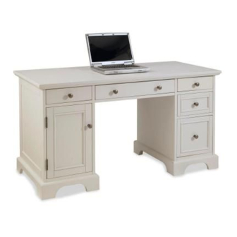
Naples
Pedestal Desk
IMPORTANT NOTE
Carefully remove all the parts from the carton and put
them individually on a soft cloth to prevent scratches
or other damages occuring to the parts.
We have taken great care in the design of this
product and request that you carefully and strictly
follow our assembly instructions to ensure a
completed product as it was designed.
Part List
A.
Top
1 pc.
M.
Keyboard Rail
1 pc.
N.
Keyboard Rail
1 pc.
O.
Keyboard Support
1 pc.
Hardware List
Hex Wrench
Cam Lock Screw
1 pc.
48 pcs.(+2 extra)
Small
Cam Lock
Hex Wrench
48 pcs.(+6 extra)
1 pc.
For assembly see instructions in carton 88 5530 182
Tools required for assembly : Phillips screwdriver
Home Styles Consumer Assistance Line 888-680-7460 and 877-831-0319
Wood Screw (long)
for side drawer
36 pcs. (+1 extra)
Wood Screw (short)
for drawer base
16 pcs.(+1 extra)
servicedesk@homestyles-furniture.com
K.
Keyboard
1 pc.
P.
Keyboard Support
1 pc.
Wood Screw (long)
Magnet
8 pcs. (+1 extra)
1 pc.
Wood Screw
Wood Screw (short)
for Magnet
6 pcs. (+1 extra)
2 pcs.(+1 extra)
L.
Keyboard
1 pc.
Q.
Keyboard Support
1 pc.
Adjustable Pin
Pull Handle
4 pcs.(+1 extra)
7 pcs.
Head Cap Bolt
Machine Screw
8 pcs. (+1 extra)
7 pcs.
Advertisement
Table of Contents

Related Manuals for Homestyles 88 5530 181


Summary of Contents for Homestyles 88 5530 181
- Page 1 88 5530 181 Naples Pedestal Desk IMPORTANT NOTE Carefully remove all the parts from the carton and put them individually on a soft cloth to prevent scratches or other damages occuring to the parts. We have taken great care in the design of this...
-
Page 2: Important Note
1 pc. (Knock-Down Construction, please refer to the last page of these instructions for drawer assembly steps) Also need the following from carton 88 5530 181 : Part List in carton 88 5530 181 Hardware List in carton 88 5530 181... - Page 3 Assembly Instructions 2/8 IMPORTANT You should keep Hex Wrench in a safe place as you may need to tighten up the Head Cap Bolts in the future. Cam Lock Screw Wood Screw for Magnet Magnet Figure 1 STEP 1 Insert Cam Lock Screws into the pre-drilled holes of Top (A), Side Panels (B) and (C), (D) and (E),...
- Page 4 Assembly Instructions 3/8 Wood Screw (long) Cam Lock Screw Cam Lock STEP 2 Attach Front Rails (F), Base (H), Back Panel (I) and Plinth (J) to Side Panel (B) with Cam Locks. (See figure 2) Attach Side Panel (C) to unit with Cam Locks. Insert 4X Wood Screw (long) into the pre-drilled holed of unit and tighten.
- Page 5 Assembly Instructions 4/8 Head Cap Bolt STEP 4 Figure 3 Assemble Keyboard Rails (M) and (N), Keyboard box (P) and (Q) with Head Cap Bolts. (See figure 3) Attach Keyboard Support (O) to unit with Cam Locks. Attach keyboard Support in between both units from Steps 2 and 3 with Head Cap Bolts. STEP 5 Place Top (A) onto unit with Cam Locks.
-
Page 6: Assemble Pull Handle To Door With Machine Screw See Figure
Assembly Instructions 5/8 STEP 6 Insert Adjustable Pins into side panels at the desired level. (See figure 5) Place Shelf (R) into position. Attach Door (S) by sliding the door lift hinges into the side panels lift hinges. (See figure 6) Figure 5 Figure 6 Assemble Pull Handle to Door with Machine Screw. -
Page 7: Part List
Assembly Instructions 6/8 Drawer (T) STEP 1 Attach T1 to T3 and T4, using a Phillips screwdriver long wood screws (4X) tighten halfway. Figure 1 Attach T2 to T3 and T4 using MAKE SURE ROLLER IS ON THE BACK long wood screws (4X) tighten halfway. - Page 8 Assembly Instructions 7/8 Drawer (U) STEP 1 Attach U1 to U3 and U4, using a Phillips screwdriver long wood screws (4X) tighten halfway. MAKE SURE ROLLER Figure 1 IS ON THE BACK Attach U2 to U3 and U4 using long wood screws (4X) tighten halfway.
- Page 9 Assembly Instructions 8/8 Drawer (V) STEP 1 Attach V1 to V3 and V4 using a Phillips screwdriver long wood screws (6X) tighten halfway. Figure 1 Attach V2 to V3 and V4 using long wood screws (6X) tighten halfway. (see Figure 1) STEP 2 Slide V5 into the grooves in V3 and V4.
Need help?
Do you have a question about the 88 5530 181 and is the answer not in the manual?
Questions and answers